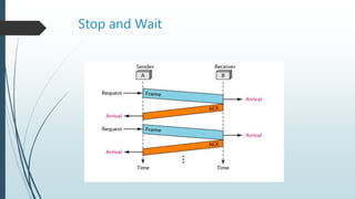
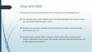
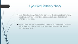
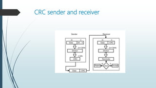
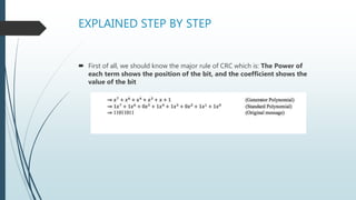
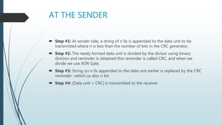
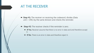
CSE350
Data Communications
East West University
PRESENTATION ON
Flow control and error control techniques in the
data link layer protocol
Presented by:
Md. Saiyadul Ferdous
ID: 2015-2-60-047
Md. Mohaiminul Hasan
ID: 2015-2-60-084
Data Link Layer
Data Link = Line Discipline + Flow Control + Error Control
Flow Control
 Flow control coordinates the amount of data that can be sent
before receiving acknowledgement.
 Flow control is a set of procedures that tells the sender how
much data it can transmit before it must wait for an
acknowledgement from the receiver.
Error Control
Error control includes both error detection and error
correction.
It allows the receiver to inform the sender if a frame
is lost or damaged during transmission and
coordinates the retransmission of those frames by
the sender.
Error and Flow Control Mechanisms
Stop-and-Wait
Go-Back-N ARQ
Selective-Repeat ARQ
Stop and Wait
Stop and Wait
 keeps a copy of the last frame until it receives an cknowledgement.
 For identification, both data frames and acknowledgements (ACK) frames
are numbered alternatively 0 and 1.
 Sender has a control variable (S) that holds the number of the recently
sent frame. (0 or 1)
 Sender starts a timer when it sends a frame. If an ACK is not received
within a allocated time period, the sender assumes that the frame was lost
or damaged and resends it
Cyclic redundancy check
 A cyclic redundancy check (CRC) is an error-detecting code commonly
used in digital networks and storage devices to detect accidental
changes to raw data.
 Cyclic codes are special linear block codes with one extra property. In a
cyclic code, if a code word is cyclically shifted (rotated), the result is
another code word.
CRC sender and receiver
EXPLAINED STEP BY STEP
 First of all, we should know the major rule of CRC which is: The Power of
each term shows the position of the bit, and the coefficient shows the
value of the bit
AT THE SENDER
 Step #1: At sender side, a string of n 0s is appended to the data unit to be
transmitted where n is less than the number of bits in the CRC generator.
 Step #2: The newly formed data unit is divided by the divisor using binary
division and reminder is obtained this reminder is called CRC, and when we
divide we use XOR Gate.
 Step #3: String on n 0s appended to the data unit earlier is replaced by the CRC
reminder –which us also n bit.
 Step #4: (Data unit + CRC) is transmitted to the receiver
AT THE RECEIVER
 Step #1: The receiver on receiving the codeword, divides (Data
unit + CRC) by the same division and checks the reminder.
 Step #2: The receiver checks if the reminder is zero.
 If Yes, Receiver assume that there is no error in data and and therefore accept
it.
 If No, There is an error in data and therefore reject it.
Thank You

Flow control and error control techniques in the data link layer protocol

  • 1.
  • 2.
    PRESENTATION ON Flow controland error control techniques in the data link layer protocol Presented by: Md. Saiyadul Ferdous ID: 2015-2-60-047 Md. Mohaiminul Hasan ID: 2015-2-60-084
  • 3.
    Data Link Layer DataLink = Line Discipline + Flow Control + Error Control
  • 4.
    Flow Control  Flowcontrol coordinates the amount of data that can be sent before receiving acknowledgement.  Flow control is a set of procedures that tells the sender how much data it can transmit before it must wait for an acknowledgement from the receiver.
  • 5.
    Error Control Error controlincludes both error detection and error correction. It allows the receiver to inform the sender if a frame is lost or damaged during transmission and coordinates the retransmission of those frames by the sender.
  • 6.
    Error and FlowControl Mechanisms Stop-and-Wait Go-Back-N ARQ Selective-Repeat ARQ
  • 7.
  • 8.
    Stop and Wait keeps a copy of the last frame until it receives an cknowledgement.  For identification, both data frames and acknowledgements (ACK) frames are numbered alternatively 0 and 1.  Sender has a control variable (S) that holds the number of the recently sent frame. (0 or 1)  Sender starts a timer when it sends a frame. If an ACK is not received within a allocated time period, the sender assumes that the frame was lost or damaged and resends it
  • 9.
    Cyclic redundancy check A cyclic redundancy check (CRC) is an error-detecting code commonly used in digital networks and storage devices to detect accidental changes to raw data.  Cyclic codes are special linear block codes with one extra property. In a cyclic code, if a code word is cyclically shifted (rotated), the result is another code word.
  • 10.
  • 11.
    EXPLAINED STEP BYSTEP  First of all, we should know the major rule of CRC which is: The Power of each term shows the position of the bit, and the coefficient shows the value of the bit
  • 12.
    AT THE SENDER Step #1: At sender side, a string of n 0s is appended to the data unit to be transmitted where n is less than the number of bits in the CRC generator.  Step #2: The newly formed data unit is divided by the divisor using binary division and reminder is obtained this reminder is called CRC, and when we divide we use XOR Gate.  Step #3: String on n 0s appended to the data unit earlier is replaced by the CRC reminder –which us also n bit.  Step #4: (Data unit + CRC) is transmitted to the receiver
  • 13.
    AT THE RECEIVER Step #1: The receiver on receiving the codeword, divides (Data unit + CRC) by the same division and checks the reminder.  Step #2: The receiver checks if the reminder is zero.  If Yes, Receiver assume that there is no error in data and and therefore accept it.  If No, There is an error in data and therefore reject it.
  • 14.