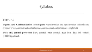
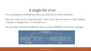
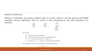
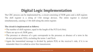
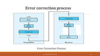
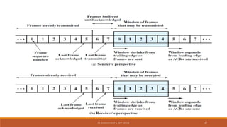
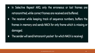
The document discusses digital data communication techniques, including asynchronous and synchronous transmission. Asynchronous transmission treats each character independently with start and stop bits, while synchronous transmission transmits blocks of data without start/stop bits using framing. Error detection techniques are covered, including parity checks which add redundant bits to detect errors, and cyclic redundancy checks which generate and check error codes using polynomials.


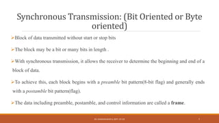
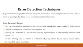
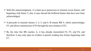
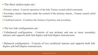
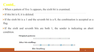
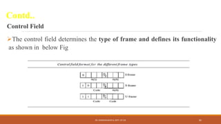
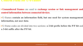
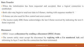
![Odd Parity:
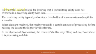
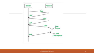
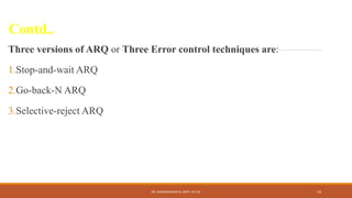
The parity bit is set by the transmitter such that the total number of ones in the character, has
become an odd number of 1s means odd parity.
If the number of 1’s is not odd at the receiver side, receiver can detect the error in the
transmission.
Eg: Input before transmission- (1110001),
Using even parity -11100010 [0 is appened]
Using odd parity -11100011 [1 is appened]
DR. GANESHKUMAR N, DEPT. OF CSE 18](https://image.slidesharecdn.com/datacommunications-unit-4-231017065703-4699a2ee/85/Data-Communications-Unit-4-pptx-18-320.jpg)
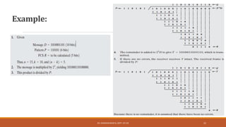
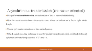
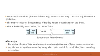
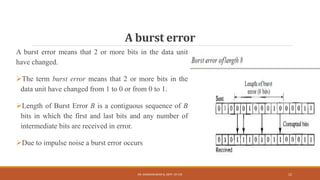
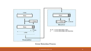
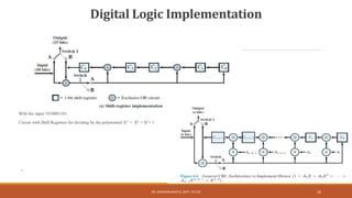
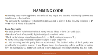
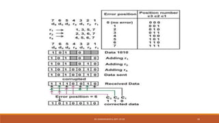
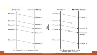
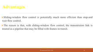
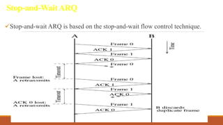
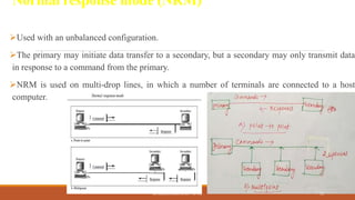
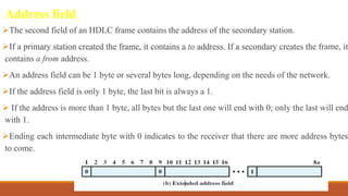
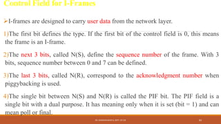
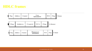
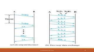
![Here k=10 (number of bits in D(X)),
P= n-k+1=6 (Pattern p=n-k+1) so n-10+1=6
For D=1010001101, we have D(X)=X9+X7+X3+X2+1. And for P=110101 we have P(X)=X5+X4+X2+1. n=6+10-1=15,
FCS(n-k=15-10=5)
The message D is multiplied with Xn-k. So D(X) multiplied with X5.
[ X5 *D(X) =X5*(X9+X7+X3+X2+1) = X14+X12 +X8 +X7+ X5
The product is divided by P.[P(X)=X5+X4+X2+1].
After the polynomial division, it end up with remainder R= 01110 which corresponds to X3+X2+X1
The message is transmitted as n= X14+X12 +X8 +X7+ X5 + X3+X2+X1
Again the transmitted message is divided by pattern P(X) at the receiver’s side, if it is no remainder then it is called as
error free transmission.
DR. GANESHKUMAR N, DEPT. OF CSE 23](https://image.slidesharecdn.com/datacommunications-unit-4-231017065703-4699a2ee/85/Data-Communications-Unit-4-pptx-23-320.jpg)


![FINAL Employee Management System[1].pptx](https://cdn.slidesharecdn.com/ss_thumbnails/finalemployeemanagementsystem1-260214165011-3f2d85c9-thumbnail.jpg?width=640&height=640&fit=bounds)
![vardhanppt[1].pptxbsjsnsnmsksjsjsnsjsjjs](https://cdn.slidesharecdn.com/ss_thumbnails/vardhanppt1-260214164941-9acb8d83-thumbnail.jpg?width=640&height=640&fit=bounds)


![team_-8[1].pptxvjigivhihigigiiggigiiggui](https://cdn.slidesharecdn.com/ss_thumbnails/team-81-241026055727-f108b207-thumbnail.jpg?width=640&height=640&fit=bounds)


