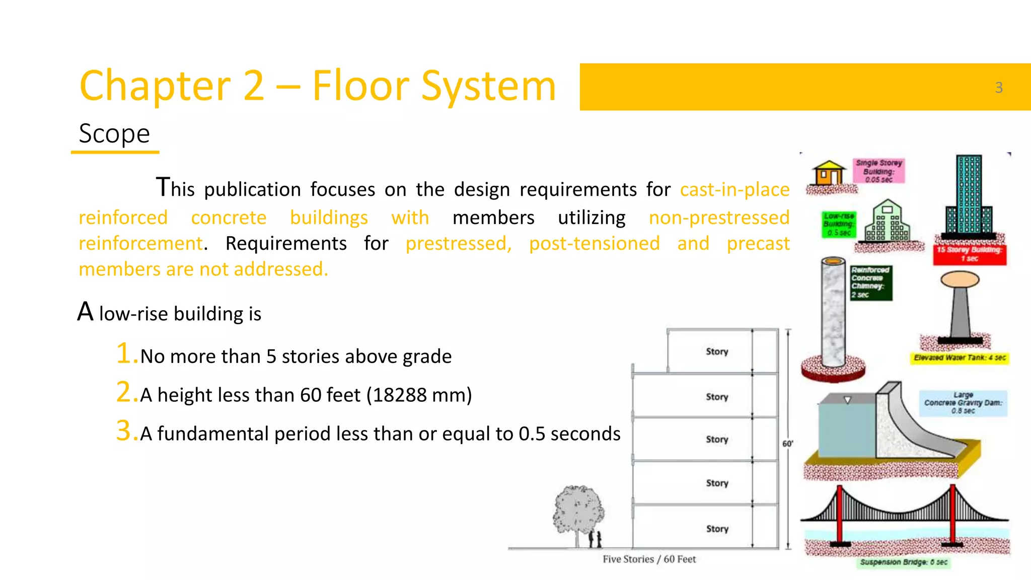
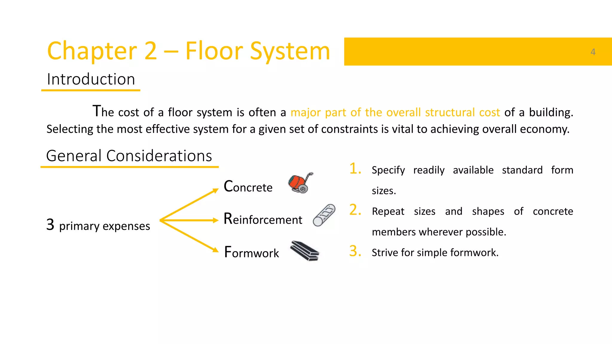
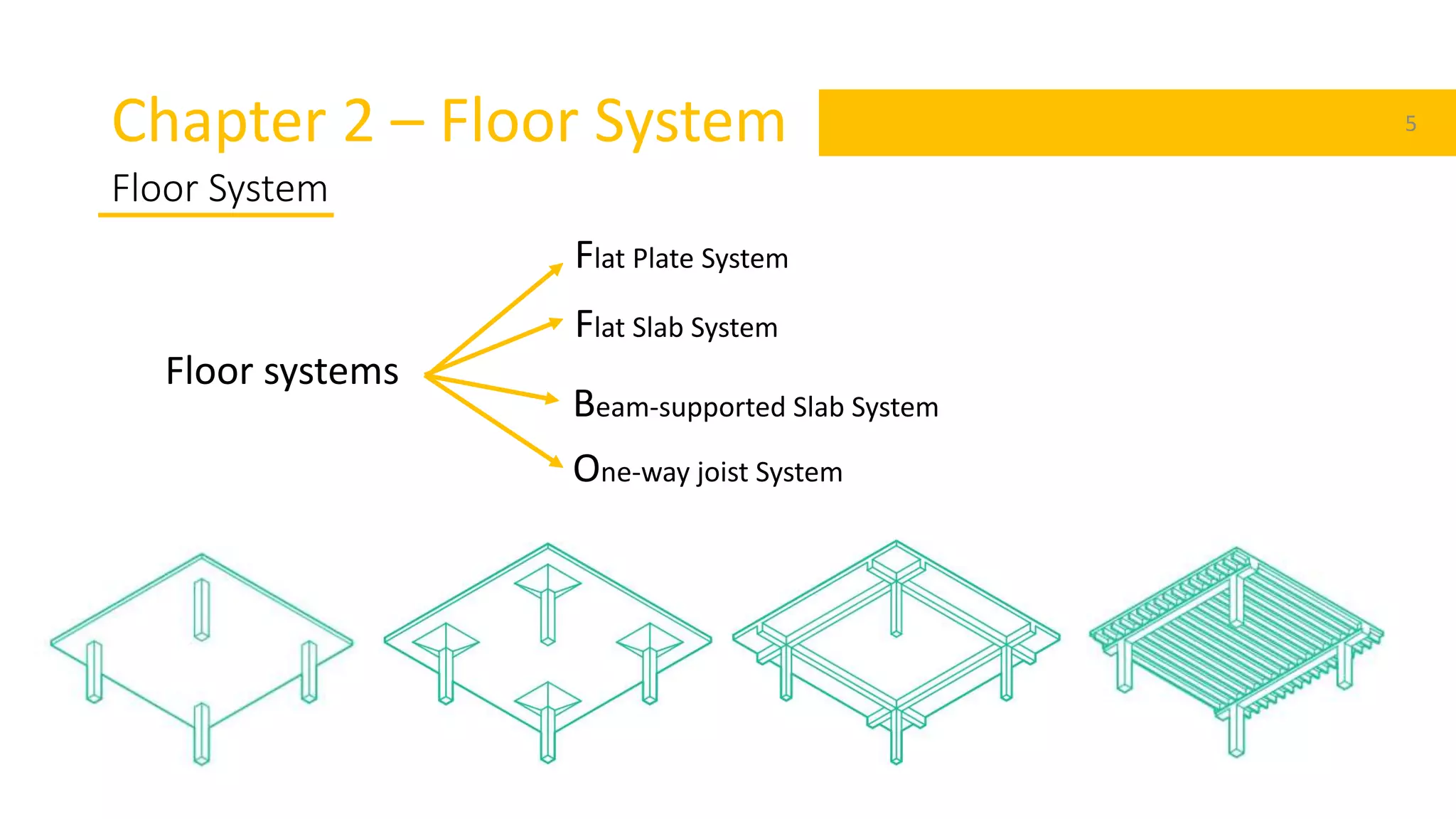
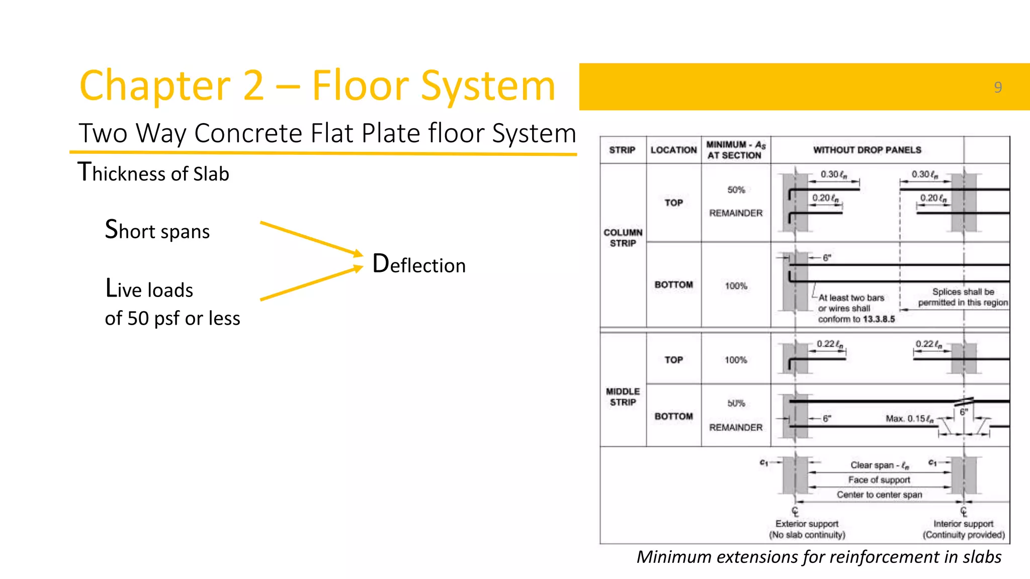
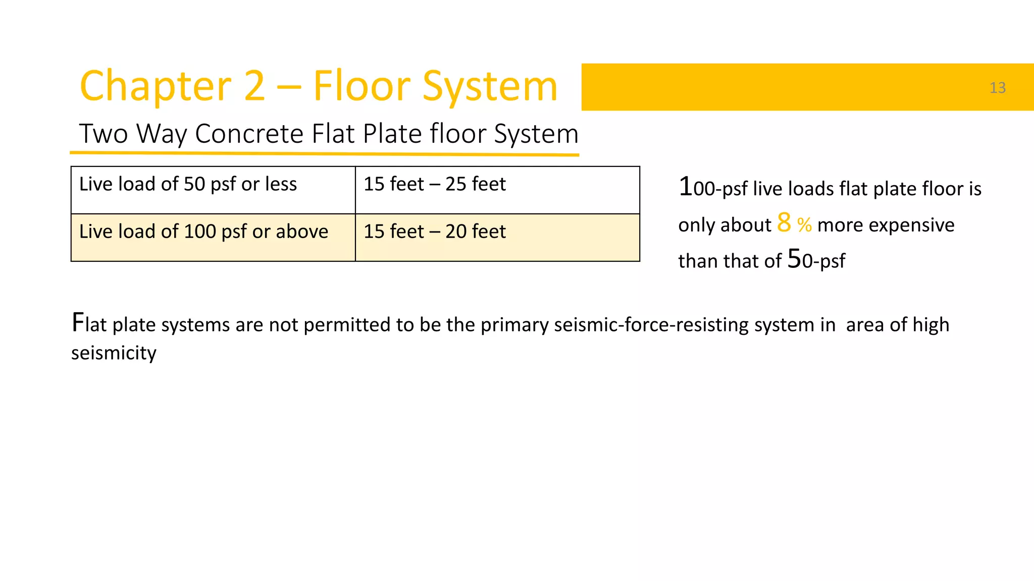
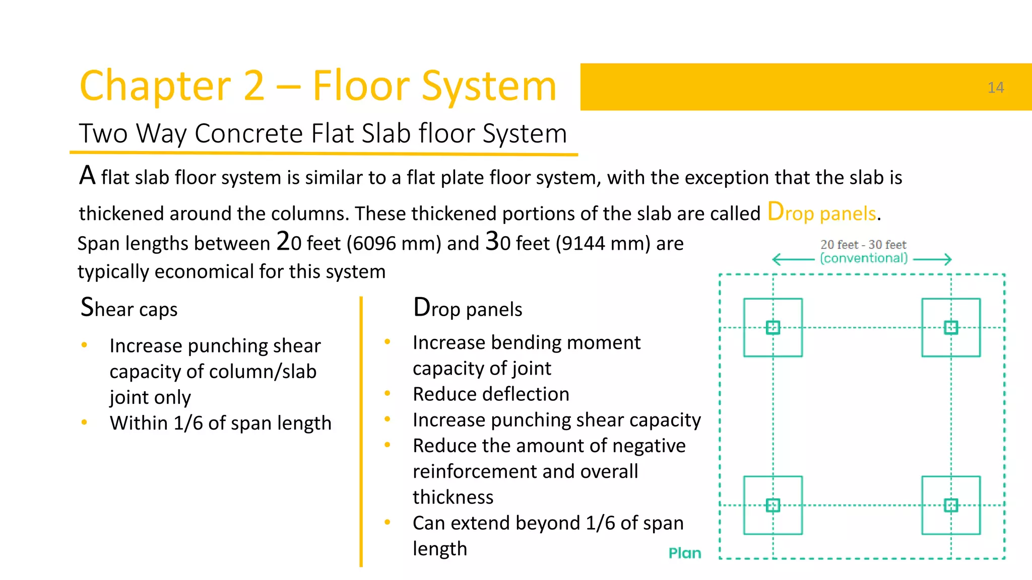
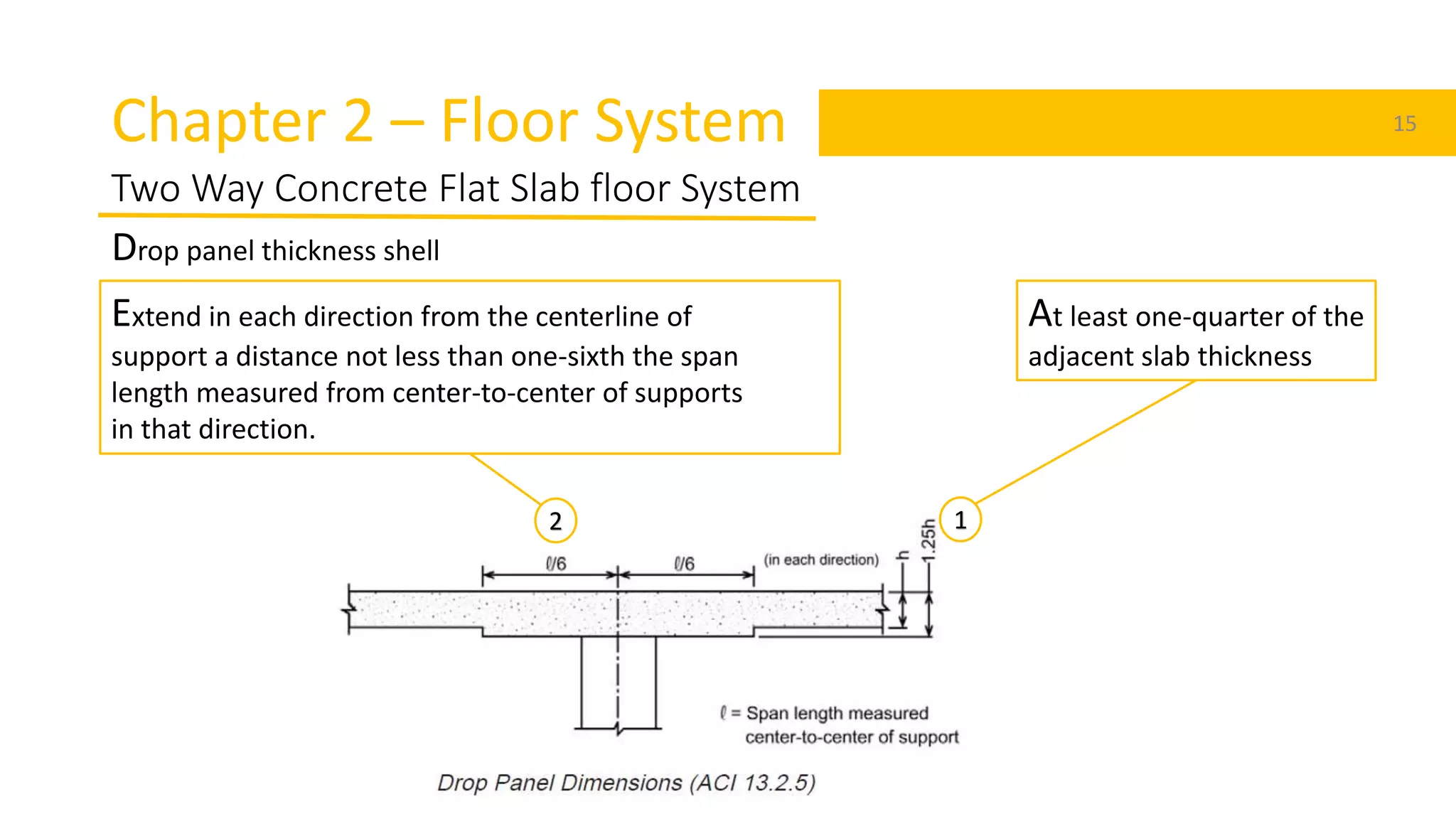
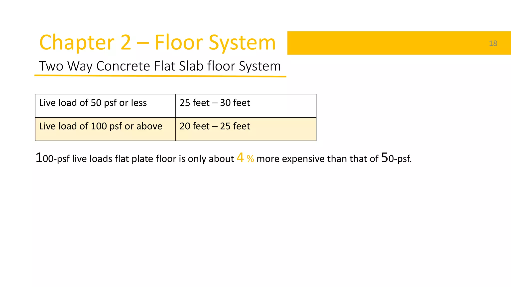
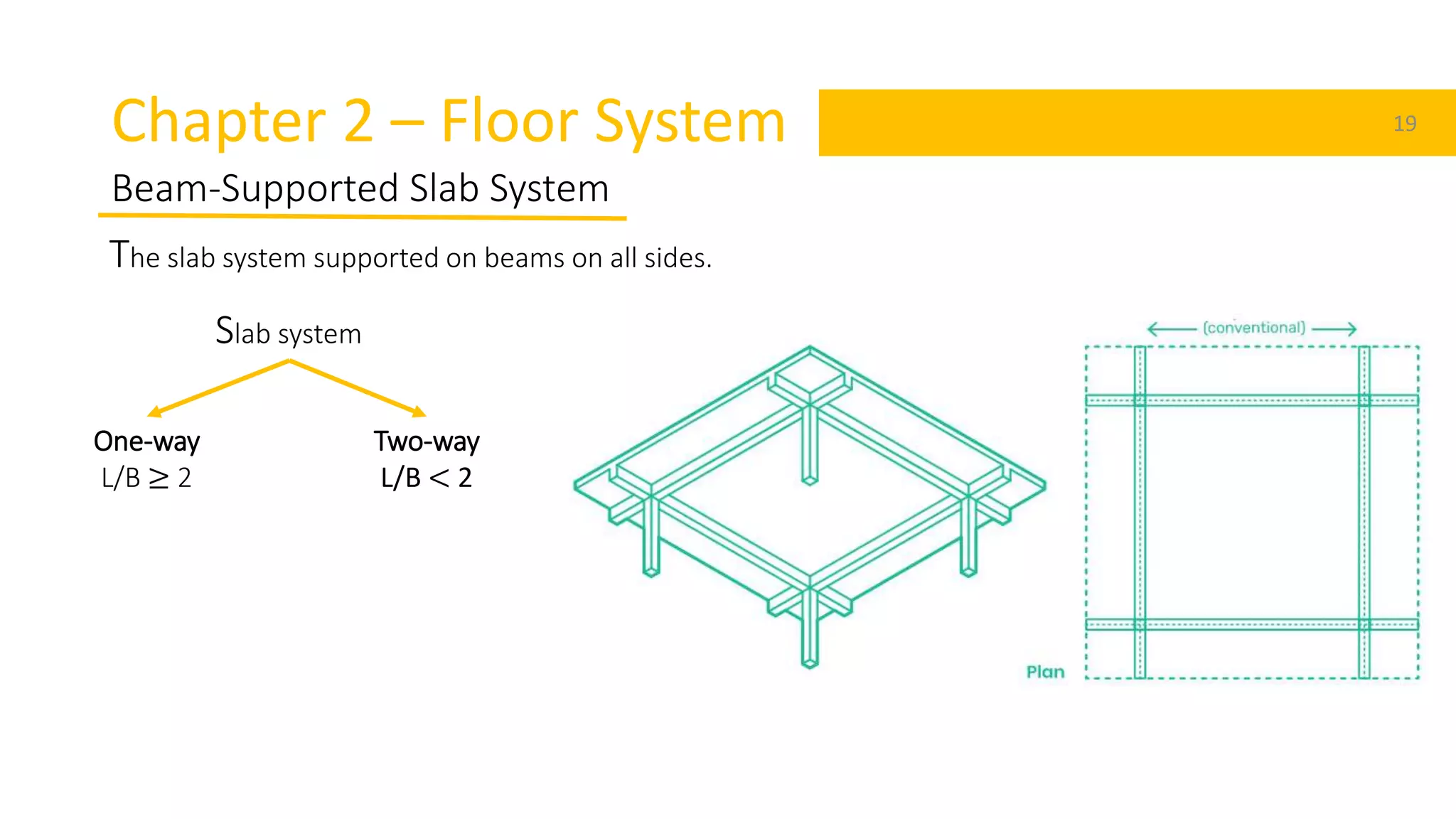
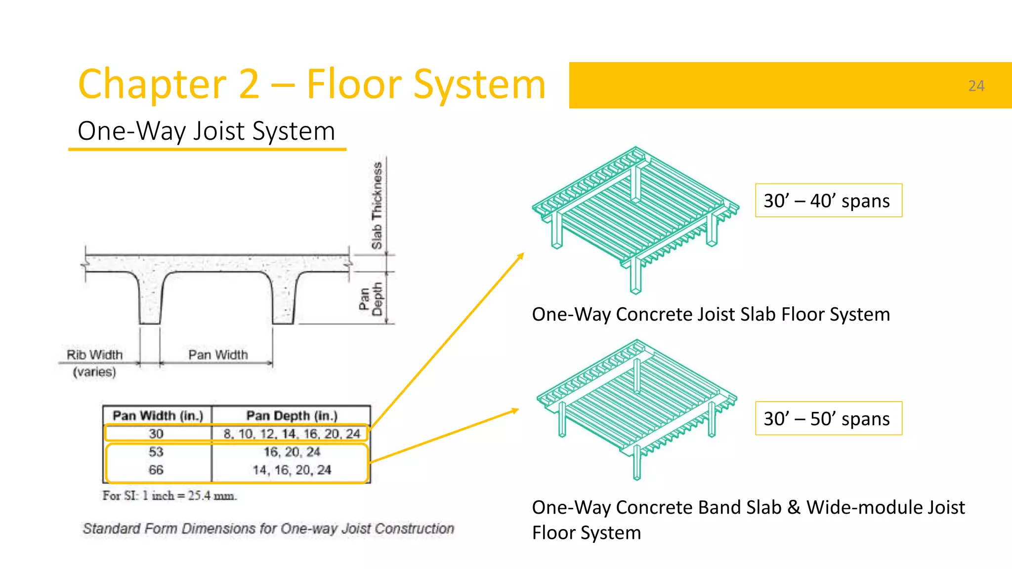
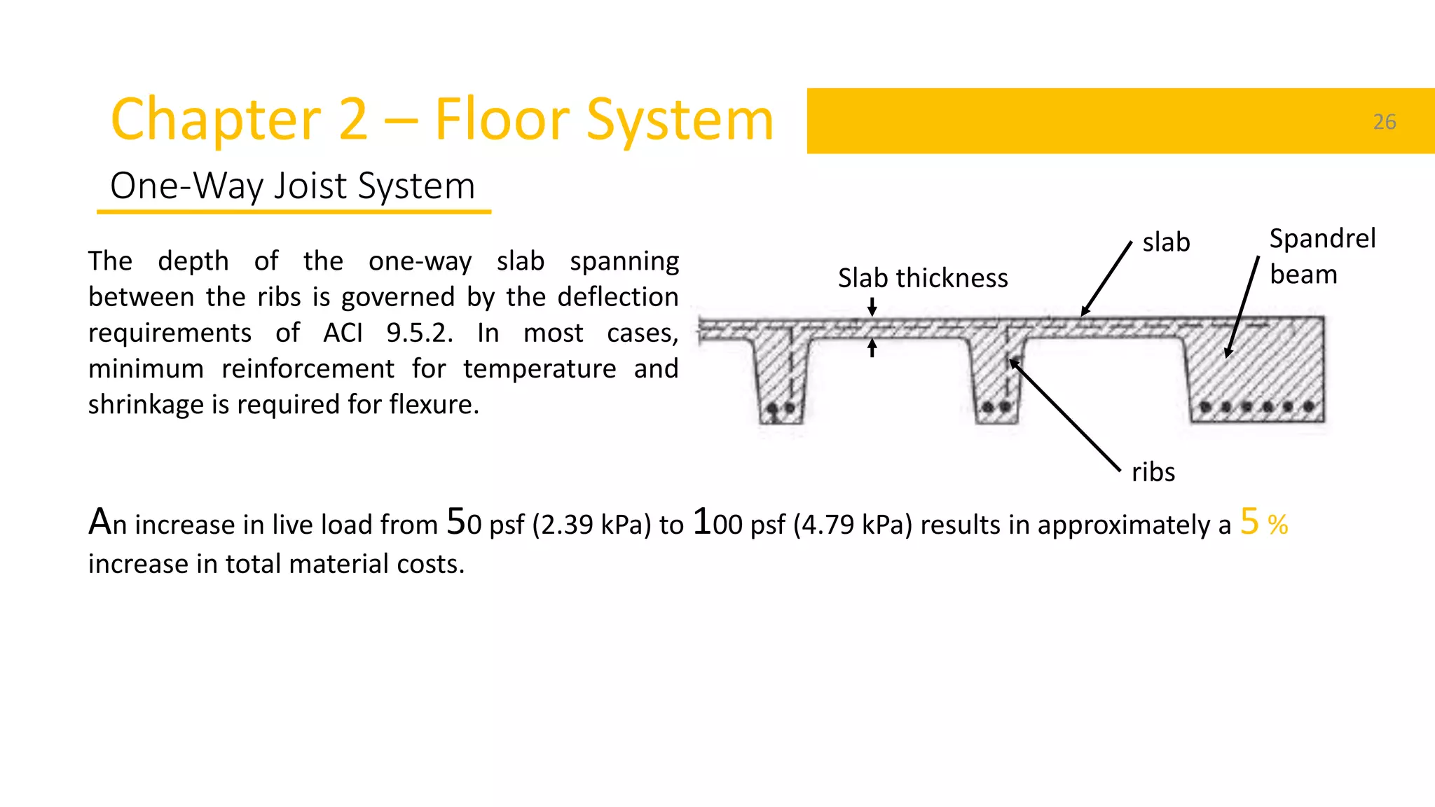
Design of Low-Rise Reinforced
Concrete Buildings
Chapter – 2 <Floor System>
Toe Myint Naing
Curtin Sarawak
Intern
KSI Engineering
1
References 2
Design of Low-Rise Reinforced Concrete Buildings
David A. Fanella, Ph.D., S.E., P.E., F.ASCE
Chapter 2 – Floor System 3
Scope
This publication focuses on the design requirements for cast-in-place
reinforced concrete buildings with members utilizing non-prestressed
reinforcement. Requirements for prestressed, post-tensioned and precast
members are not addressed.
A low-rise building is
1.No more than 5 stories above grade
2.A height less than 60 feet (18288 mm)
3.A fundamental period less than or equal to 0.5 seconds
Chapter 2 – Floor System 4
Introduction
The cost of a floor system is often a major part of the overall structural cost of a building.
Selecting the most effective system for a given set of constraints is vital to achieving overall economy.
3 primary expenses
General Considerations
Concrete
Reinforcement
Formwork
1. Specify readily available standard form
sizes.
2. Repeat sizes and shapes of concrete
members wherever possible.
3. Strive for simple formwork.
Chapter 2 – Floor System 5
Floor System
Floor systems
Flat Plate System
Flat Slab System
Beam-supported Slab System
One-way joist System
Chapter 2 – Floor System 6
A flat plate floor system is a two-way concrete slab supported directly on columns
Span lengths between 15 feet (4572 mm) and 25 feet (7620 mm) when subjected to moderate live
loads.
Advantages
• Ease of formwork installation
• Easier reinforcement placement
• Flexibility in room layout
• Less construction time
Two Way Concrete Flat Plate floor System
Chapter 2 – Floor System 7
Fy,psi
Without drop panels
Exterior panels
Interior
panelsWithout
edge beams
With edge
beams §
40,000 κn/33 κn/36 κn/36
60,000 κn/30 κn/33 κn/33
75,000 κn/28 κn/31 κn/31
Minimum thickness of slab
The minimum thickness shell not be less than 5 inches.
For two-way construction, κn is the length of clear span in the long direction, measured face-to-face of
supports in slabs without beams
Two Way Concrete Flat Plate floor System
§ Slabs with beams between columns along exterior edges. The value of α 𝑓 for the edge beam shall not be less than 0.8.
Chapter 2 – Floor System 8
Minimum thickness of slab
Two Way Concrete Flat Plate floor System
Chapter 2 – Floor System 9
Thickness of Slab
Live loads
of 50 psf or less
Short spans
Deflection
Minimum extensions for reinforcement in slabs
Two Way Concrete Flat Plate floor System
Chapter 2 – Floor System 10
Thickness of Slab
Live loads
of 100 psf or
greater
Long spans
Two-way or Punching
shear
Spandrel Beam
Two Way Concrete Flat Plate floor System
Chapter 2 – Floor System 11
Assumption
• Square-edge column of size c1 bending perpendicular to
the slab edge with a three-sided critical section and 𝛼s = 30
• Column supports a tributary area, A
• Square bays
• Gravity load moment transferred between the slab and
edge column in accordance with the Direct Design Method
requirement of ACI 13.6.3.6
• 4,000 psi (27 580 kPa) normal weight concrete
Total factored load, qu
Preliminary slab thickness, h
qu A/𝑐1
2 d/𝑐1 d h = d + 1
1
4
”
Two Way Concrete Flat Plate floor System
Chapter 2 – Floor System 12
Thickness of Slab
• Increase slab thickness/column sizes
Shear Cap
• Shear Caps or Shear Reinforcement
Not viable
Shear Reinforcement
Two Way Concrete Flat Plate floor System
Chapter 2 – Floor System 13
Live load of 50 psf or less 15 feet – 25 feet
Live load of 100 psf or above 15 feet – 20 feet
100-psf live loads flat plate floor is
only about 8 % more expensive
than that of 50-psf
Flat plate systems are not permitted to be the primary seismic-force-resisting system in area of high
seismicity
Two Way Concrete Flat Plate floor System
Chapter 2 – Floor System 14
A flat slab floor system is similar to a flat plate floor system, with the exception that the slab is
thickened around the columns. These thickened portions of the slab are called Drop panels.
Span lengths between 20 feet (6096 mm) and 30 feet (9144 mm) are
typically economical for this system
Shear caps Drop panels
• Increase punching shear
capacity of column/slab
joint only
• Within 1/6 of span length
• Increase bending moment
capacity of joint
• Reduce deflection
• Increase punching shear capacity
• Reduce the amount of negative
reinforcement and overall
thickness
• Can extend beyond 1/6 of span
length
Two Way Concrete Flat Slab floor System
Chapter 2 – Floor System 15
At least one-quarter of the
adjacent slab thickness
12
Drop panel thickness shell
Extend in each direction from the centerline of
support a distance not less than one-sixth the span
length measured from center-to-center of supports
in that direction.
Two Way Concrete Flat Slab floor System
Chapter 2 – Floor System 16
Drop panel thickness shell
Fy,psi
With drop panels
Exterior panels
Interior
panelsWithout
edge beams
With edge
beams
40,000 κn/36 κn/40 κn/40
60,000 κn/33 κn/36 κn/36
75,000 κn/31 κn/34 κn/34
The minimum slab thickness required by ACI 9.5.3 for flat slabs is 10 % less than that required for flat plates.
The minimum thickness shell not be less than 4 inches.
Two Way Concrete Flat Slab floor System
§ Slabs with beams between columns along exterior edges. The value of α 𝑓 for the edge beam shall not be less than 0.8.
Chapter 2 – Floor System 17
Drop panel dimension shell
Two Way Concrete Flat Slab floor System
Chapter 2 – Floor System 18
Two Way Concrete Flat Slab floor System
Live load of 50 psf or less 25 feet – 30 feet
Live load of 100 psf or above 20 feet – 25 feet
100-psf live loads flat plate floor is only about 4 % more expensive than that of 50-psf.
Chapter 2 – Floor System 19
Beam-Supported Slab System
One-way
L/B ≥ 2
Two-way
L/B < 2
The slab system supported on beams on all sides.
Slab system
Chapter 2 – Floor System 20
Beam-Supported Slab System
Minimum thickness, h
Simply
supported
One end
continuous
Both ends
continuous
Cantilever
Member Members not supporting or attached to partitions or other construction
likely to be damaged by large deflections
Solid one-way
slabs
κ/20 κ/24 κ/28 κ/10
Beams or ribbed
one-way slabs
κ/16 κ/18.5 κ/21 κ/8
Note:
For members with normal weight concrete and Grade 60 reinforcement.
One-way slab thickness shell
Chapter 2 – Floor System 21
Beam-Supported Slab System
𝛼 𝑓𝑚 is the average value of 𝛼 𝑓 for all beams on
edges of a panel
𝛼 𝑓 shell be calculated in accordance with
8.10.2.7
𝛽 is the ratio of clear spans in long to short
directions of slab
Two-way slab thickness shell
Chapter 2 – Floor System 22
Beam-Supported Slab System
Seismic-force-resisting system
Chapter 2 – Floor System 23
One-Way Joist System
A one-way joist system consists of evenly spaced concrete joists (ribs) spanning in one
direction, a reinforced concrete slab that is cast integrally with the joists and beams that span between
the columns perpendicular to the joists
One-Way Concrete Joist Slab Floor System One-Way Concrete Band Slab & Wide-module
Joist Floor System
Chapter 2 – Floor System 24
One-Way Joist System
One-Way Concrete Joist Slab Floor System
One-Way Concrete Band Slab & Wide-module Joist
Floor System
30’ – 40’ spans
30’ – 50’ spans
Chapter 2 – Floor System 25
One-Way Joist System
To achieve overall formwork economy,
• The depth of supporting beam and joist should be the
same
• The beams should be wider than column
Chapter 2 – Floor System 26
One-Way Joist System
ribs
slab Spandrel
beam
An increase in live load from 50 psf (2.39 kPa) to 100 psf (4.79 kPa) results in approximately a 5 %
increase in total material costs.
The depth of the one-way slab spanning
between the ribs is governed by the deflection
requirements of ACI 9.5.2. In most cases,
minimum reinforcement for temperature and
shrinkage is required for flexure.
Slab thickness
Thank
sFor your attention
Any
Question?

Floor systems

  • 1.
    Design of Low-RiseReinforced Concrete Buildings Chapter – 2 <Floor System> Toe Myint Naing Curtin Sarawak Intern KSI Engineering 1
  • 2.
    References 2 Design ofLow-Rise Reinforced Concrete Buildings David A. Fanella, Ph.D., S.E., P.E., F.ASCE
  • 3.
    Chapter 2 –Floor System 3 Scope This publication focuses on the design requirements for cast-in-place reinforced concrete buildings with members utilizing non-prestressed reinforcement. Requirements for prestressed, post-tensioned and precast members are not addressed. A low-rise building is 1.No more than 5 stories above grade 2.A height less than 60 feet (18288 mm) 3.A fundamental period less than or equal to 0.5 seconds
  • 4.
    Chapter 2 –Floor System 4 Introduction The cost of a floor system is often a major part of the overall structural cost of a building. Selecting the most effective system for a given set of constraints is vital to achieving overall economy. 3 primary expenses General Considerations Concrete Reinforcement Formwork 1. Specify readily available standard form sizes. 2. Repeat sizes and shapes of concrete members wherever possible. 3. Strive for simple formwork.
  • 5.
    Chapter 2 –Floor System 5 Floor System Floor systems Flat Plate System Flat Slab System Beam-supported Slab System One-way joist System
  • 6.
    Chapter 2 –Floor System 6 A flat plate floor system is a two-way concrete slab supported directly on columns Span lengths between 15 feet (4572 mm) and 25 feet (7620 mm) when subjected to moderate live loads. Advantages • Ease of formwork installation • Easier reinforcement placement • Flexibility in room layout • Less construction time Two Way Concrete Flat Plate floor System
  • 7.
    Chapter 2 –Floor System 7 Fy,psi Without drop panels Exterior panels Interior panelsWithout edge beams With edge beams § 40,000 κn/33 κn/36 κn/36 60,000 κn/30 κn/33 κn/33 75,000 κn/28 κn/31 κn/31 Minimum thickness of slab The minimum thickness shell not be less than 5 inches. For two-way construction, κn is the length of clear span in the long direction, measured face-to-face of supports in slabs without beams Two Way Concrete Flat Plate floor System § Slabs with beams between columns along exterior edges. The value of α 𝑓 for the edge beam shall not be less than 0.8.
  • 8.
    Chapter 2 –Floor System 8 Minimum thickness of slab Two Way Concrete Flat Plate floor System
  • 9.
    Chapter 2 –Floor System 9 Thickness of Slab Live loads of 50 psf or less Short spans Deflection Minimum extensions for reinforcement in slabs Two Way Concrete Flat Plate floor System
  • 10.
    Chapter 2 –Floor System 10 Thickness of Slab Live loads of 100 psf or greater Long spans Two-way or Punching shear Spandrel Beam Two Way Concrete Flat Plate floor System
  • 11.
    Chapter 2 –Floor System 11 Assumption • Square-edge column of size c1 bending perpendicular to the slab edge with a three-sided critical section and 𝛼s = 30 • Column supports a tributary area, A • Square bays • Gravity load moment transferred between the slab and edge column in accordance with the Direct Design Method requirement of ACI 13.6.3.6 • 4,000 psi (27 580 kPa) normal weight concrete Total factored load, qu Preliminary slab thickness, h qu A/𝑐1 2 d/𝑐1 d h = d + 1 1 4 ” Two Way Concrete Flat Plate floor System
  • 12.
    Chapter 2 –Floor System 12 Thickness of Slab • Increase slab thickness/column sizes Shear Cap • Shear Caps or Shear Reinforcement Not viable Shear Reinforcement Two Way Concrete Flat Plate floor System
  • 13.
    Chapter 2 –Floor System 13 Live load of 50 psf or less 15 feet – 25 feet Live load of 100 psf or above 15 feet – 20 feet 100-psf live loads flat plate floor is only about 8 % more expensive than that of 50-psf Flat plate systems are not permitted to be the primary seismic-force-resisting system in area of high seismicity Two Way Concrete Flat Plate floor System
  • 14.
    Chapter 2 –Floor System 14 A flat slab floor system is similar to a flat plate floor system, with the exception that the slab is thickened around the columns. These thickened portions of the slab are called Drop panels. Span lengths between 20 feet (6096 mm) and 30 feet (9144 mm) are typically economical for this system Shear caps Drop panels • Increase punching shear capacity of column/slab joint only • Within 1/6 of span length • Increase bending moment capacity of joint • Reduce deflection • Increase punching shear capacity • Reduce the amount of negative reinforcement and overall thickness • Can extend beyond 1/6 of span length Two Way Concrete Flat Slab floor System
  • 15.
    Chapter 2 –Floor System 15 At least one-quarter of the adjacent slab thickness 12 Drop panel thickness shell Extend in each direction from the centerline of support a distance not less than one-sixth the span length measured from center-to-center of supports in that direction. Two Way Concrete Flat Slab floor System
  • 16.
    Chapter 2 –Floor System 16 Drop panel thickness shell Fy,psi With drop panels Exterior panels Interior panelsWithout edge beams With edge beams 40,000 κn/36 κn/40 κn/40 60,000 κn/33 κn/36 κn/36 75,000 κn/31 κn/34 κn/34 The minimum slab thickness required by ACI 9.5.3 for flat slabs is 10 % less than that required for flat plates. The minimum thickness shell not be less than 4 inches. Two Way Concrete Flat Slab floor System § Slabs with beams between columns along exterior edges. The value of α 𝑓 for the edge beam shall not be less than 0.8.
  • 17.
    Chapter 2 –Floor System 17 Drop panel dimension shell Two Way Concrete Flat Slab floor System
  • 18.
    Chapter 2 –Floor System 18 Two Way Concrete Flat Slab floor System Live load of 50 psf or less 25 feet – 30 feet Live load of 100 psf or above 20 feet – 25 feet 100-psf live loads flat plate floor is only about 4 % more expensive than that of 50-psf.
  • 19.
    Chapter 2 –Floor System 19 Beam-Supported Slab System One-way L/B ≥ 2 Two-way L/B < 2 The slab system supported on beams on all sides. Slab system
  • 20.
    Chapter 2 –Floor System 20 Beam-Supported Slab System Minimum thickness, h Simply supported One end continuous Both ends continuous Cantilever Member Members not supporting or attached to partitions or other construction likely to be damaged by large deflections Solid one-way slabs κ/20 κ/24 κ/28 κ/10 Beams or ribbed one-way slabs κ/16 κ/18.5 κ/21 κ/8 Note: For members with normal weight concrete and Grade 60 reinforcement. One-way slab thickness shell
  • 21.
    Chapter 2 –Floor System 21 Beam-Supported Slab System 𝛼 𝑓𝑚 is the average value of 𝛼 𝑓 for all beams on edges of a panel 𝛼 𝑓 shell be calculated in accordance with 8.10.2.7 𝛽 is the ratio of clear spans in long to short directions of slab Two-way slab thickness shell
  • 22.
    Chapter 2 –Floor System 22 Beam-Supported Slab System Seismic-force-resisting system
  • 23.
    Chapter 2 –Floor System 23 One-Way Joist System A one-way joist system consists of evenly spaced concrete joists (ribs) spanning in one direction, a reinforced concrete slab that is cast integrally with the joists and beams that span between the columns perpendicular to the joists One-Way Concrete Joist Slab Floor System One-Way Concrete Band Slab & Wide-module Joist Floor System
  • 24.
    Chapter 2 –Floor System 24 One-Way Joist System One-Way Concrete Joist Slab Floor System One-Way Concrete Band Slab & Wide-module Joist Floor System 30’ – 40’ spans 30’ – 50’ spans
  • 25.
    Chapter 2 –Floor System 25 One-Way Joist System To achieve overall formwork economy, • The depth of supporting beam and joist should be the same • The beams should be wider than column
  • 26.
    Chapter 2 –Floor System 26 One-Way Joist System ribs slab Spandrel beam An increase in live load from 50 psf (2.39 kPa) to 100 psf (4.79 kPa) results in approximately a 5 % increase in total material costs. The depth of the one-way slab spanning between the ribs is governed by the deflection requirements of ACI 9.5.2. In most cases, minimum reinforcement for temperature and shrinkage is required for flexure. Slab thickness
  • 27.
  • 28.

Editor's Notes

  • #4 The time taken (in seconds) for each complete cycle of oscillation (i.e., one complete back-and-forth motion) is the same and is called Fundamental Natural Period T of the building. Value of T depends on the building flexibility and mass; more the flexibility, the longer is the T, and more the mass, the longer is the T. In general, taller buildings are more flexible and have larger mass, and therefore have a longer T. On the contrary, low- to medium-rise buildings generally have shorter T (less than 0.5 sec).
  • #5 Of the three, formwork has the greatest influence, which accounts for about 50 percent of the total in place costs. 1. do not have the budget to accommodate the additional cost of custom formwork 2. Maximum overall savings is achieved when formwork can be used from bay to bay and from floor to floor. 3. The cost savings associated with a reduction in material quantities is negligible compared to the cost savings associated with simple formwork.
  • #8 The thickness of a flat plate will usually be controlled by deflection requirements for relatively short spans and live loads of 50 psf (2.39 kPa) or less. In such cases, the flexural reinforcement at the critical sections in the column and middle strips will be about the minimum amount specified in ACI 13.3. Thus, using a slab thickness greater than the minimum required for serviceability is not economical, since a thicker slab requires more concrete without a reduction in reinforcement. Also, since the minimum slab thickness requirements are independent of the concrete compressive strength, specifying 4,000-psi (27 580 kPa) concrete is the most economical; using a concrete strength greater than 4,000 (27 580 kPa) psi increases cost without a reduction in slab thickness.
  • #9 The thickness of a flat plate will usually be controlled by deflection requirements for relatively short spans and live loads of 50 psf (2.39 kPa) or less. In such cases, the flexural reinforcement at the critical sections in the column and middle strips will be about the minimum amount specified in ACI 13.3. Thus, using a slab thickness greater than the minimum required for serviceability is not economical, since a thicker slab requires more concrete without a reduction in reinforcement. Also, since the minimum slab thickness requirements are independent of the concrete compressive strength, specifying 4,000-psi (27 580 kPa) concrete is the most economical; using a concrete strength greater than 4,000 (27 580 kPa) psi increases cost without a reduction in slab thickness.
  • #10 The thickness of a flat plate will usually be controlled by deflection requirements for relatively short spans and live loads of 50 psf (2.39 kPa) or less. In such cases, the flexural reinforcement at the critical sections in the column and middle strips will be about the minimum amount specified in ACI 13.3. Rebar want to reduce, increase thickness…Thus, using a slab thickness greater than the minimum required for serviceability is not economical, since a thicker slab requires more concrete without a reduction in reinforcement. Also, since the minimum slab thickness requirements are independent of the concrete compressive strength, specifying 4,000-psi (27 580 kPa) concrete is the most economical; using a concrete strength greater than 4,000 (27 580 kPa) psi increases cost without a reduction in slab thickness.
  • #11 Shear strength requirement for slab are given in ACI 11.11 using a higher concrete compressive strength f’c is not the most effective way of increasing nominal shear strength of concrete. ***Increasing the thickness of the slab and/or increasing the column dimensions are typically the most cost-effective solutions to two-way shear problems. Shear stresses developed at edge and corner columns are particularly critical, since they are subjected to relatively large unbalanced moments. Providing spandrel beams significantly increases shear strength at perimeter columns, but there is additional material and forming costs associated with such members and they may not fit into the architectural scheme.
  • #12 primarily due to the minimum thickness requirements for deflection.
  • #13 Provisions for headed shear stud reinforcement are given in ACI 11.11.5; such reinforcement provides an economical means of resisting shear stresses and helps alleviate congestion at slab-column joints Shear caps are used to improve the punching shear capacity of the column/slab joint only. Does not extend into the span beyond one-sixth of the span length.
  • #14 primarily due to the minimum thickness requirements for deflection.
  • #17 580120
  • #18 Drop panel dimensions are also controlled by formwork considerations.
  • #19 primarily due to the minimum thickness requirements for deflection.
  • #23 seismic-force-resisting system
  • #24 It is usually more cost-effective to frame the joists in the long direction. Advantage -longer span with heavy load -Reduced dead load due to void -M&E can place in void -Good vibration resistance
  • #25 The thickness of the slab spanning between the joists is usually controlled by fire-resistance requirements, since the structural requirements of the slab are minimal. Wide-module joists are economical for long spans [30 feet to 50 feet (9144 mm to 15 240 mm)] and/or heavier loads.
  • #26 Joist width can be tailored to satisfy virtually any requirement. In usual situations, the thinnest practical width will usually be adequate for structural requirements. Column-line joists can be made part of the lateral-force-resisting system, and the width can be adjusted as needed to resist the combined load effects.