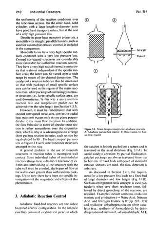
This document discusses different forms of catalysts that can be used in fixed-bed reactors. Random packings of spheres, cylinders, or hollow cylinders are commonly used and provide good gas-catalyst mass transfer due to turbulence. However, heat transfer is poorer across the gas-catalyst boundary in random packings. Monolith catalyst structures like parallel channels or stacked plates can provide more uniform heating and flow distribution. The document evaluates different catalyst forms in terms of mass transfer, heat transfer, pressure drop, and catalyst concentration to optimize the design of fixed-bed reactors.

![202 Industrial Reactors
To minimize these costs it is therefore neces-
sary to maximize the conversion in the reactor
and avoid as far as possible inert accompanying
substances in the reaction mixture. With irre-
versible reactions (e.g., partial oxidations) the
trend is therefore towards a highly concentrated,
approximately stoichiometric feed composition,
which may occasionally be in the explosive
range. The resulting problems are discussed in
Chapters 4 and 6.
2. Catalyst Forms for Fixed-Bed
Reactors
The heart of a fixed-bed reactor and the site
of the chemical reaction IS the catalyst. The pro-
cesses taking place on the catalyst may formally
be subdivided into the following separate steps:
I) Diffusion of the reactants from the gas space
through the outer gas- particle boundary lay-
er, macropores, and micropores
2) Chemisorption on active centers
3) Surface reactions
4) Desorption of the products
5) Back-diffusion of the products into the gas
space
Since most reactions take place with a con-
siderable heat of reaction, a corresponding heat
transport is superimposed on the mass transport.
The control of the microkinetics, consisting
of micropore diffusion, chemisorption, surface
reaction, and desorption, is the task of the cata-
lyst developer and IS not discussed further here.
If the catalyst is specified together with its mi-
croklnetic properties, then reaction conditions
(feedstock concentrations, pressure, temperature
profile, and residence time) can be found that
lead to optimum yields. The reaction engineer
must determine these conditions and ensure that
they are maintained in an Industrial reactor.
In the case of selectivity-sensitive multistep
reactions, any deviation from the optimum val-
ues Inevitably leads to a decrease in yield. ThiS
appIJes to deviations from the uniform residence
time distribution due to flow dispersion and flow
bypass phenomena in the fixed bed, as well as to
deviations from uniform reaction conditions in
the catalyst as a result of mass-transport resis-
tance in the particles and the outer boundary
layer [2.1].
Vol. B4
The influence of mass-transport resistance in
the particles can only be excluded if the critical
reaction rate is substantially lower than the mass
transport velocity. This leads on the one hand to
the need for good external mass transfer (i.e. to
reasonable flow conditions in the packed bed), as
well as to short diffusion paths in catalyst parti-
cles and sufficiently large pores. On the other
hand (in the case of exothermic reactions) the
local reaction rate must be controlled and limited
by the packed-bed temperature.
Temperature control thus plays a predomi-
nant role in selective reaction control in general,
and in particular in the case ofexothermic multi-
step reactions. Under nonadiabatic conditions,
catalysts must therefore be assembled and ar-
ranged in the fixed bed in such a way as to ensure
good heat transport to the heat-transfer medi-
um.
A further requirement placed on the catalyst
is a low flow pressure loss. This applies par-
ticularly if the reaction conversion in a single
throughput is low, so that the reaction has to be
carried out with a large circulating gas ratio
(Fig. 1.2), as well as to off-gas pUrification, in
which large off-gas streams must be handled
with minimal additional cost.
Finally, the catalyst should be available in a
sufficiently high concentration in order to keep
the construction volume of the reactor low. The
decisive parameters here are the speCific external
catalyst surface ap ( = square meters of cata-
®
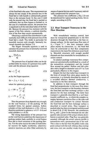
CD
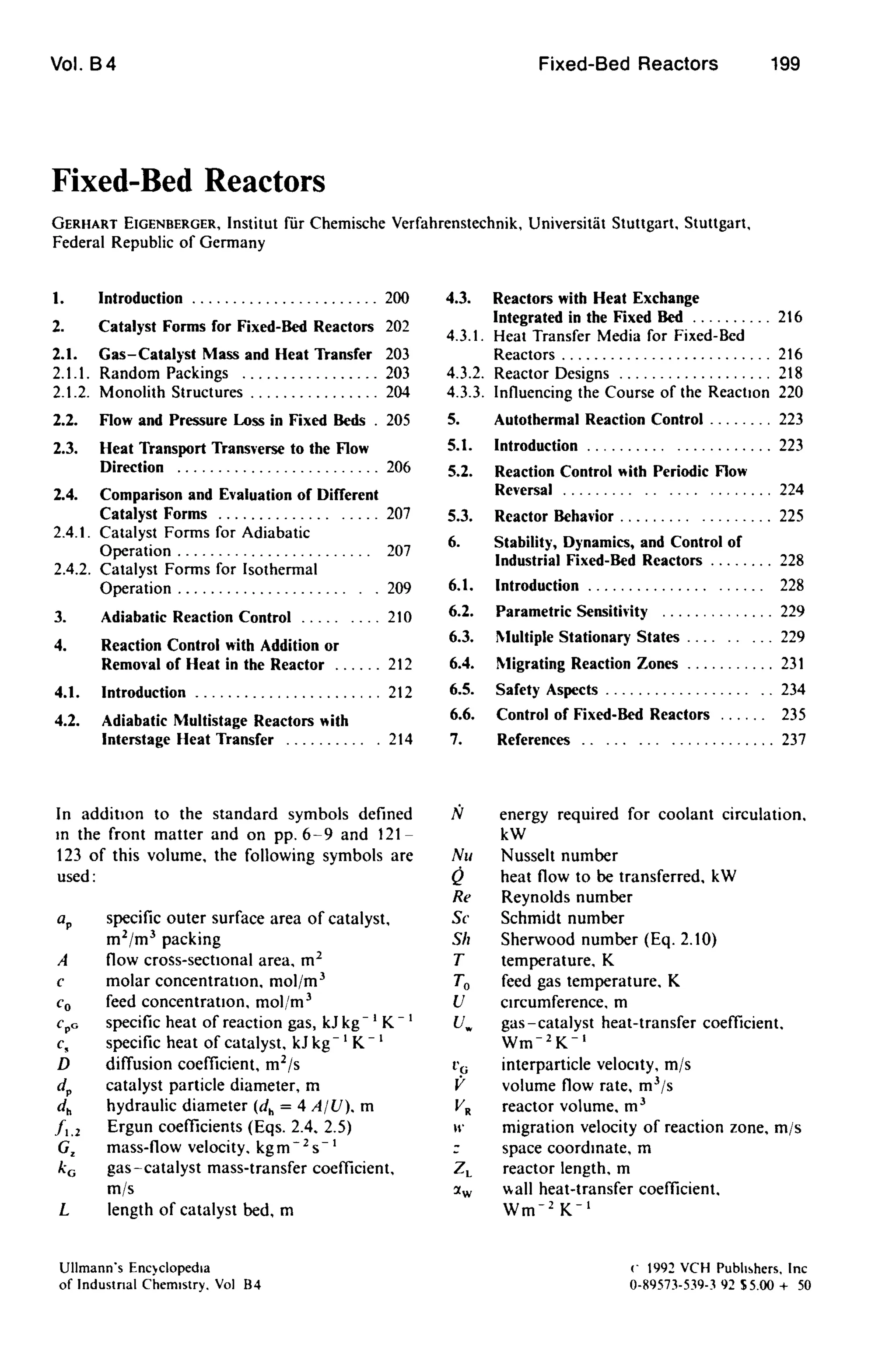
Figure 2.1. Usual shapes of monohth catalysts
A) Square-channel monohth. B) Parallel-plate monolith.
C) Corrugated-plate monohth](https://image.slidesharecdn.com/fixedbed-200303072027/85/Fixed-bed-4-320.jpg)
![204 Industrial Reactors
tion, providing an insight into the overall highly
inhomogeneous conditions. The visualization
technique is based on the reaction of traces of
ammonia in the gas stream with a catalyst sur-
face impregnated with manganese chloride solu-
tion . The conversion to manganese dioxide is al-
ready so fast under ambient conditions that it
practically depends only on the external mas -
transfer resistance of the gas boundary layer.
The intensity of the dark coloration is thus di-
rectly proportional to the local reaction rate of
the urface reaction. At a constant ammonia
concentration in the gas flow it is thus also pro-
portional to the local mass transfer, and if the
rna s transfer and heat transfer are equivalent,
also to the local heat transfer [2.2).
Figure 2.3 shows that the local conditions in
random packings are much more complex than
as umed in current conventional models. Never-
theless, the models for fixed beds containing a
larger number of catalyst particles over the cro s
section can provide reliable information if it is
borne in mind that they only describe the mean
value of a process that varies greatly a regards
detail. For the same reason, it is inappropriate to
compare model predictions with a few local tem-
perature or concentration measurement . In-
deed, a certain degree of averaging is also nece -
sary in the measurement procedure (see Section
2.2).
The literature contains a number of correla-
tion equations for the mean gas - catalyst mass
tran fer and heat transfer as a function of gas
propertie , cataly t geometry, and flow condi-
tions [2.3], [2.4). However, in practice they play
only a minor role for catalyst packings since
design and simulation calculations are frequent-
ly performed with a model that is quasi-homo-
geneous, at least with regard to temperature
(-+ Model Reactors and Their Design Equa-
tions, pp. 140- 144). The reason for this are the
above-mentioned trong local fluctuations,
which make differentiation between the gas tem-
perature and catalyst temperature difficult.
2.1.2. Monolith tructures
In contrast to random packings, the external
heat transfer and mass transfer in monolith cata-
lysts is much more uniform, but they can also
become limiting factors at high reaction rates.
This applies in particular to channel-type mono-
liths with narrow parallel channels. where the
Vol. B 4
A
B
Figure 2.4. Visualization of mass transfer in monolith
structures (now from left to right)
A) Square duct; 8) Corrugated monolith 12.5]
flow i generally laminar under indu trial oper-
ating conditions. Example include monolith
catalysts with a square-channel cross section for
automobile exhaust purification and for the re-
moval of nitrogen oxides from flue gases.
Figure 2.4 shows results of the visualization
of the local mass transfer by using the ammonia -
manganese chloride reaction (Section 2.1.1).
The marked decrease in coloration in the flow
direction is mainly the result of the increa ing
con umption of ammonia in the wall boundary
layer, so that the reactants diffusing to the wall
have to travel an ever increasing distance from
the flow core (build up of the laminar boundary
layer). The depletion is particularly pronounced
in the corners, since two reaction surfaces meet
here. The more acute their enclo ed angle, the
greater is the depletion in the corner region and
the smaller is the contribution of the wall surface
Tabte I. Asymptotic dimensionless laminar now heat or
mass-transfer coefficients Nu = ,,_ . dh/;'G (constant wall
conditions) and fanning friction factor I for pressure drop
fo.p = 2/("Zud:) . I'G for ducts of different cross section
[2.6)
Geometr) Nu I dh
{;; 2.47 13.33 20 v 3
~ 2.98 14.23 a
0 3.34 15.05 3a
~ 3.66 16.00 a
0 7.54 24.00 20](https://image.slidesharecdn.com/fixedbed-200303072027/85/Fixed-bed-6-320.jpg)
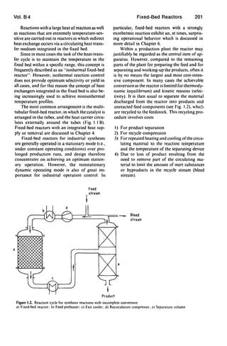
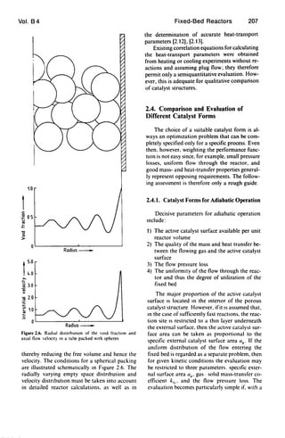
![Vol. B4 Fixed-Bed Reactors 205
102
D Re=600
• Re=1200
C> Re=1800
+ Re=2200
t
0
..-
~ 101
ti
..~
'"~
'"
10°L-__~-L~~WWUL~__L-~~~~~~~__L-~-W~
10-4 10-3 10-2 10-1
Z*=Zl/(dh · Re· Sc)_
Figure 2.5. BehavIOr of lhe dimensionless heal-transfer and mass-tran,fer coefficients over the dimensIOnless tube length
Nu ='w db/i.". Sh = kG d.ID
to further heat transfer and mass transfer. The
effiCiency of channel monoliths of equal cross-
sectional area but different shape therefore
decreases in the sequence: cIrcle. hexagon.
rectangle. tnangle. ThiS is illustrated in Table t.
which gives the asymptotic dimensionless mass-
transfer and heat-transfer coefficients for tubes
of the above cross sections. As Figure 2.5 shows.
the asymptotic limiting value is established after
a flow length roughly corresponding to to times
the hydraulic channel diameter. The asymptotic
limiting value from Table t can therefore be used
to perform estimation calculations in conven-
tional industnal monolith catalysts with a large
length-to-diameter ratio. For more accurate cal-
culations the radially and aXIally vanable veloci-
ty. conCf'ntratJon. and temperature profiles must
also be taken into account [2.7].
In contrast to the monolith types discussed so
far. the flow conditions m corrugated-plate
monoliths (Fig. 2. t C) are turbulent under nor-
mal industrial velocities. The uniformity of the
mass-transfer distribution [2.8] depends on geo-
metrical parameters (wave form. amplitude.
wavelength. angle of inCidence). The transfer
coefficients are considerably higher than
those of lammarly traversed channel monoliths
(Fig. 2.4 B). but the pressure loss IS also high.
These structures offer conSIderable advantages
for convective heat transport transverse to the
flow direction and for transverse mIXIng. which
are discussed m more detail in the following sec-
tions.
2.2. Flow and Pressure Loss in
Fixed Beds
Conventional industrial catalyst forms differ
considerably as regards pressure loss. For exam-
ple. for equal mean dImensIOns and the same
proportIon of empty space. random packmgs
generally have a conSIderably higher pressure
loss than monolith structures. and among these.
corrugated structures have a hIgher pressure loss
than monoliths with straight parallel channels.
Mass transfer and heat transfer are strongly cor-
related with the pressure loss. For reasons of
enelgy demand. the catalyst form for a given
process is chosen to combme the reqUIred mass
transport and heat transport with the lowest
pressure loss. However. It should be borne in
mind that the flow into the fixed-bed reactor
(Fig. t. t) is generally achieved by means of a
feed pipe and a distnbution hood These must
therefore be constructed so that the fixed bed or
tube bundle is uniformly traversed. and the gas
reSIdence time m each tube or each flow filament](https://image.slidesharecdn.com/fixedbed-200303072027/85/Fixed-bed-7-320.jpg)
![Vol. B4
pp.624-628). In the first case the "fixed bed"
consists of several layers of platinum wire
gauzes, and tn the second case. of a porous silver
layer several centimeters in height. The bed di-
ameters can be up to several meters.
On account of the difficulties involved with
obtaining uniform flow as weIl as for structural
reasons, the disk concept is limited to smaIl cata-
lyst volumes. The radial flow concept (Fig. 3.1 C)
is used where large amounts of catalyst are in-
volved. The catalyst packing is accommodated in
the space between two concentric screen rings or
perforated plate rings. and is traversed radially.
either from the inside to the outside or from the
outside to the inside. ThIS design is particularly
suitable for large catalyst volumes as well as for
operation at elevated pressure, since at moderate
reactor diameters the catalyst volume can be
varied over a WIde range by altering the reactor
length, without affecting the flow-through length
of the packing.
A critical feature of packed radial-flow reac-
tors is the shape of the upper bed closure. A
simple horizontal covenng is not practicable
since a gap through which unreacted gas can pass
is then formed due to the unavoidable settling of
the packing. The arrangement shown tn Figure
3.2 has proved effective since It produces mixed
axial and radIal flow through the bed in the
upper bed closure. The required geometrical
shape must be determtned by simulation of the
local two-dimensional flow through the packtng
[3.1].
The advantages of monohth catalysts with
straight, parallel channels for adiabatic reactors
have already been referred to in Section 2.4.1.
Since monolith catalysts are usually produced
with a rectangular cross section. the fixed bed is
constructed by arranging these individual mono-
liths tn rows in the form of a large "box". Con-
ventional DENOX reactors for removing NO,
from power station flue gases are therefore de-
signed as rectangular chambers (FIg. 3.3). The
catalyst is often arranged in the form of several
layers in senes. the spaces between the individual
layers permitting cross-mixtng, so that the influ-
ence of nonuniform flow as weIl as any possible
local blockage of the next layer can be compen-
sated to some extent.
Reference is made tn Section 2.2 to the Im-
portance of UnIform flow into and through
adiabatic fixed-bed reactors. ThIS is not easy
to achieve. particularly with low-pressure-Ioss
monolith reactors. and requires a careful deSIgn
Fixed-Bed Reactors 211
Perforated
wall
Unperforated
wall
AXial radial
gas flow
zone
Radial
gas flow
zone
Figure 3.2. Upper bed clo,ure In a radlal-flO, redctor [3 IJ
Structure
c8Catalyst
element
Catalyst module
Flue gas + NHJ In
t
Flue gas out
Catalyst
layers
Figure 3.3. Reaction chamber for removdl of mtrogen ox-
Ides from power station flue gas [3 2J](https://image.slidesharecdn.com/fixedbed-200303072027/85/Fixed-bed-13-320.jpg)
![212 Industrial Reactors
of the inflow hood. On account of the low pres-
sure loss, unfavorable flow conditions in the out-
flow hood may also affect the flow behavior
through the catalyst bed.
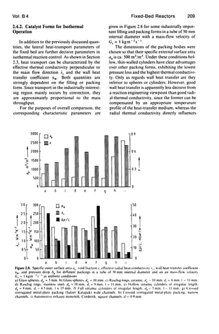
Figure 3.4 shows the velocity distribution m
front of the monolith inlet for an industrially
housed automobile catalyst [2.11]. Since the flow
cannot follow the sudden widening of the inlet
funnel, one third of the total cross section is tra-
versed at a velocity that is roughly three times the
mean velocity. It can be estimated that, with uni-
form flow through the catalyst, half the catalyst
volume would be sufficient for the same mean
conversion. Also, bends in the feedpipe can lead
to swirl-type components and thus contribute to
nonuniform flow.
Purely adiabatic fixed-bed reactors are used
mainly for reactions with a small heat of reac-
tion. Such reactions are primarily involved in gas
purification, in which small amounts of interfer-
mg components are converted to noninterfering
compounds. The chambers used to remove NO,
from power station flue gases, with a catalyst
,.::,
u
o
~
>
15
4 6
Mass flow
• • 204 kg/h
o 0 70 kg/h
.. .. 35 kg/h
8 10
Diameter, em-
Figure 3,4, Velocity dl'tnbutlon In an Industnally housed
dutomoblle catalyst [2 11)
Vol. 84
volume of more than 1000 m3
, are the largest
adiabatic reactors, and the exhaust catalysts for
internal combustion engines, with a catalyst vol-
ume of ca. 1 L, the smallest. Typical chemical
applications include the methanation of CO and
CO2 residues in NH3 synthesis gas, as well as the
hydrogenation of small amounts of unsaturated
compounds in hydrocarbon streams. The latter
case requires accurate monitoring and regulation
when hydrogen is in excess, in order to prevent
complete methanation due to an uncontrolled
rise in temperature, a so-called runaway (see
Chap. 6).
4. Reaction Control with Supply or
Removal of Heat in the Reactor
4.1. Introduction
In the majority of fixed-bed reactors for in-
dustrial synthesis reactions, direct or indIrect
supply or removal of heat in the catalyst bed is
utilized to adapt the temperature profile over the
flow path as far as possible to the requirements
of an optimal reaction pathway. Here a clear
developmental trend can be observed, which is
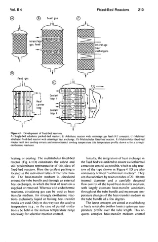
illustrated schematically in Figure 4.1.
Development started with the adiabatic reac-
tor (Fig, 4.1 A), which on account ofthe adiabat-
ic temperature change could only be operated to
give a limited conversion. Higher conversions
were achieved at the same mean temperature lev-
el when several adiabatic stages were introduced,
with intermediate heating or cooling after each
stage. The sImplest form involves injecting hot or
cold gas between the stages (Fig. 4.1 8). For a
constant tube diameter. the main disadvantages
of thIS temperature control strategy are cross-
sectional loading, which increases from stage to
stage, and the mixing of hot and cold streams.
which IS energetically unfavorable. The composi-
tion is changed by injection. which can have a
positive or negative effect on the desired reaction.
The next development was the replacement
of injection cooling by interstage heat exchang-
ers, through which the required or released heat
of reactIOn is supplied or removed (FIg. 4.1 C).
The development of reactors in which the
heat-exchange surfaces are integrated in the
fixed bed to supply or remove the heat of reac-
tion as close as possible to the reactIOn sIte
occurred in parallel WIth the development of
multistage adiabatic reactors WIth mtermediate](https://image.slidesharecdn.com/fixedbed-200303072027/85/Fixed-bed-14-320.jpg)
![Vol. B4
1000 I
I
I
800 I
I
I
I
600 I
I
I
:;-' 400 I
>-- I ..
000
I ..I 3
200
!D
Boiling
heat transfer
~o '"
.c _
.. ....... E
0[i
Liquid convection
heat transfer
c: '"
~~o ..
1: E
Fixed-Bed Reactors 217
0
'"
~ ..'"......
'"..
3 ~
u:
Gas convection
heat transfer
Figure 4.4. Application ranges for common heat-transfer media
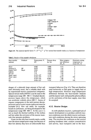
The following equation has been derived for
the evaluation of heat-transfer media without
phase change [4.11]:
Q
!!,:rc
(l73 . cp
N036-~
(4.2)
where Qis the heat flow transferred by the heat-
transfer medium while Its temperature increases
by exactly I1Tc ' N IS the required pump power,
and Q, cp ' and '1 are the density, specific heat
capacity, and viscosity of the heat-transfer medi-
um. For liquid heat-transfer media, the equation
IS derived from the pressure drop in a turbulently
traversed, hydraulically smooth pipe. It is practi-
cal to solve Equation (4.2) for the pump power'
. [Q J2 75N- -
11T.,
(4.3)
Thus the reqUIred power vanes as almost the
third power of Q/11Tc' The component '10 25;
c~ 75. Q2, which depends only on the physical
properties of the heat-transfer medIUm, is plot-
ted as a functIOn of temperature in Figure 4.5.
ThiS shows the exceptional heat-transfer proper-
ties of water that result from ItS density and, In
particular, its high speCific heat. as well as the
properties of gases (air) and vapors (water va-
por), which are about seven orders of magnitude
worse. Common heat-transfer oils and salt melts
(sodIUm nitrate) lie close together, but about an
order of magnitude above water. The poor per-
formance of molten sodium compared to heat-
transfer oils and salt melts is noteworthy
To test Equation 4.3 on a more realistic ex-
ample of the coohng of a multitubular reactor, a
quadratic tube bundle (cross section 1.5 x 1.5 m)
with fourfold passage of the coolant was de-
signed by using detailed equations for pressure
drop and heat transfer [4.12] for vanous heat-
transfer media. The heat release of 1650 kW in
1591 (37 x 43) tubes of 30 mm external diameter
and 4 m length corresponds to the conditIOns in
a partial oxidation reaction. A temperature rise
between feed and outlet of 11Tc = 5 K was as-
sumed for the heat-transfer medIUm (additional-
ly 150 K for air and water vapor). Table 2 lists as
results the required pump power N, the pressure
drop in the cooling cirCUIt I1p (whereby p = 1 bar
exit pressure was assumed for water vapor and
air), and the excess temperature of the reactor
wall above the heat-transfer medIUm tempera-
ture I1Tw• assuming constant wall temperature
along the length of the tube. It was shown that
the results of these more precise deSign equatlon~
for the hquid heat-transfer media can be corre-
lated with the equatIOn
/Ii =7800 - - - -" [ QJ2 73 '1° P
11T., c; 73 . (/
(44)
This represents a good confirmation of Equation
(4.3).
Water is thus the ideal heat-transfer medium
within Its temperature range. For higher temper-
atures molten salts have increasingly replaced
the previously more commonly used heat-trans-
fer Oils. Salt melts cover a larger temperature
range and have the particular advantage over
Oils that they are incombustible. The potential](https://image.slidesharecdn.com/fixedbed-200303072027/85/Fixed-bed-19-320.jpg)
![Vol. B4
transfer medium circuit (throughput, tempera-
ture, heat transfer). When liqUId or vaporiz-
ing heat-transfer media are used, the heat-trans-
fer coefficients are usually one order of magni-
tude greater than those on the catalyst side.
which facilitates the task as regards the heat-
transfer medium. On the other hand, with
strongly exothermic, selectivity-sensitive reac-
tions (especially partial oxidations), a tempera-
ture constancy of the heat-transfer medium of
ca. 1DC is often required. This leads to a high
energy requirement for circulation (according to
Eq. 4.4) and necessitates extremely careful de-
sign and control of the heat-transfer medium cir-
cuit.
Tubular reactors of the type shown in Figure
4.1 D have been in use longest and have been
furthest developed. In the case of a vaporizmg
heat-transfer medium an arrangement as shown
in Figure 4.6 is generally chosen, in which the
liquid heat-transfer medium surrounds the sta-
tionary tube bundle. The rising vapor bubbles
escape through the ascending pipe into a vapor
drum, where they are separated from the liquid.
A circulation flow is estabhshed due to the differ-
ence in density in the downpipe (pure liquid) and
in the reactor jacket, which means that circulat-
mg pumps are generally not required. The heat-
transfer medium temperature is regulated VIa the
saturated vapor valve. Specific details of this reg-
ulation are discussed in Section 6.6.
If uniform supply and removal of heat-trans-
fer medIUm via annular channels is ensured. thiS
arrangement provides reliable isothermal reac-
tion control. Since a steam cushIOn can form
under the upper tube floor, the active catalyst
layer should begin only at a deeper level.
Apart from the type of multltubular reactor
shown in Figure 4.6, other multitubular reactors
are sometimes used in which the catalyst bed is
arranged around the tubes and the heat-transfer
mt!dium flows through the tubes (Fig. 4.78). An
interestmg new development has been intro-
duced by Lmde (Fig. 4.7 A): the tube bundle IS
composed of counterwound spirals in which up-
wardly flowmg water IS evaporated. The tubes
run into a vertical vapor drum located at the
reactor head. The tube bundle is connected to a
central downpipe at the bottom so that. as m the
arrangement m Figure 4.6, a natural circulation
of the evaporating water is established. Advan-
tages in construction and in the heat transfer
from the reaction gas to the tubes of the bundle
are claimed for thiS deSign [4.13].
Feed gas
;7!
.I ,
I
• I
t I
I
Fixed-Bed Reactors
Saturated
steam
219
Figure 4.6. Multltubular reactor With bolhng water cool·
109
CirculatIOn systems with parallel and crossed
cocurrent or countercurrent flow of the heat-
transfer medium (Fig. 4.8) are commonly em-
ployed for hquld heat-transfer media. The main
part of the heat-transfer medIUm is generally cir-
culated with a high-capacIty pump in order to
achieve uniform heat-exchange conditions. while
a partial stream IS passed through a heat ex-
changer for supplying or removing the heat of
reaction. The deSired heat-transfer medIUm tem-
perature is attamed by regulating this partIal
stream. WIth exothermic reactions the heat ex-
changer IS normally a steam generator which
produces saturated steam at a pressure corre-
sponding to a boihng point of 30-80C below
the maximum coolmg temperature.
A superheater fed with a further partial
stream of the heat-transfer medium can if neces-
sary be connected downstream of the steam gen-
erator. The arrangement with separate external
UnIts. shown schematically m Figure 4.8 has
structural and maintenance advantages over a
common arrangement In the tube-free interIor of
the reactor [4.14].
Apparatus constructIOn companies speCializ-
ing m these reactors have developed a detailed
and comprehenSive know-how as regards flow
control of the heat-transfer medIUm [4 15]. ThiS
concerns the UnIform supply and removal of the
heat-transfer medIUm. which generally takes
place via external annular channels. as well as the](https://image.slidesharecdn.com/fixedbed-200303072027/85/Fixed-bed-21-320.jpg)
![220 Industrial Reactors
Steam
Recycle
Feedwaler
®
Figure 4.7. A) Design concept of the Linde isothennal re-
actor for methanol synthesis; B) Cut through the tube
bundle surrounded by catalyst pellets (from [4.16])
flow control within the reactor. Here a distinc-
tion is made between parallel flow control and
cros ed flow control. Parallel flow control
(Fig. 4.8 B) is achieved by two rectifier plates
with narrow bore . On account of the pre sure
los through the bores suitably arranged over the
Vol. 8 4
reactor radiu , a uniform flow profile is pro-
duced over the cross section with uniform heat
removal conditions between the di tributor
plates. The advantage of this arrangement i that
the whole reactor can be equipped with tubes.
However, due to the nonuniform flow condi-
tions in the inflow and outflow region of the
heat-transfer medium, only the region between
the distributor plates should be filled with active
catalyst. Heat transfer is low because of the par-
allel flow of the heat transfer medium, and the
pre sure loss in the distributor plates does not
contribute to improving the heat transport. For
this reason this arrangement is preferably used
for reactions with a moderate heat of reaction.
In reactions with a large heat of reaction,
e pecially partial oxidations, tran verse flow
control is more widely used, generally in a radial-
ly symmetrical arrangement with baffie plates, as
illustrated in Figure 4.8 A. Since the heat re-
moval conditions are poorly defined in the re-
gion of the flow deflection, with the change from
a tran ver e stream to a parallel stream and back
to a transverse stream, this region should be free
of tubes. A difficulty arises from the constant
change of the flow cross section in the radial
direction. However, this can be alleviated, for
example, by providing pressure-relief bores in
the baffie plates, increasing in number towards
the reactor axis. In this way constant heat-trans-
fer conditions should be achieved over the reac-
tor radius. In ummary, ensuring uniform heat
transfer conditions as regards the heat-transfer
medium thus requires a considerable flow tech-
nology know-how. Some recent publications il-
lustrate the major differences in the behavior of
different tube sections that can arise due to an
inadequate design and layout of the heat-trans-
fer medium circuit [4.2)- [4.4).
4.3.3. Influencing the Course of the Reaction
The cour e of the reaction (i.e., the conver-
sion and selectivity or yield) can be deci ively
influenced by the arrangements made for con-
trolling the heat-transfer medium. The most ob-
vious, although technically most complex solu-
tion, i to arrange different heat-transfer medium
circuits so as to achieve a stepwise approxima-
tion of an optimum temperature profile. The
purposeful utilization of the temperature change
of the heat-transfer medium flowing through the
reactor is, however, technically simpler. and is](https://image.slidesharecdn.com/fixedbed-200303072027/85/Fixed-bed-22-320.jpg)
![Vol. B4
® ®
.J
J I Circulation
turbine
Fixed-Bed Reactors
Steam
generator
Steam
Feed
water
221
Figure 4.8. Heat-transfer medIum control In tube-bundle fixed-bed reactors
A) Cross flo. B) Parallel flo
discussed here in connection with cocurrent or
countercurrent cooling of a fixed-bed reactor in-
volving an exothermIc reaction.
Figure 4.9 shows temperature profiles for
three different ways of controllIng the cooling
stream in a partial oxidation reaction. If the
coolant is circulated so fast that its temperature
in the reactor scarcely alters. then its flow direc-
tion is irrelevant and a temperature profile with
a pronounced temperature maximum becomes
established; thIS is typical ofstrongly exothermIC
reactions (Fig. 4.9 A). If the coolant IS CIrculated
in cocurrent and its velocIty is chosen so that it
becomes noticeably hotter over its path. an al-
most isothermal temperature behavIor can be
achieved (Fig. 4.9 B). ThIS is because the reactive
gas at the inlet IS in contact WIth the coldest
coolant and the cooling temperature rises in step
with the consumption of the reactants. so that
the reaction rate remains VIrtually constant over
a fairly long section [4.5]- [4.7]. This stabilizing
effect of cocurrent cooling has hardly been ex-
ploited up to now in industrIal reactors. This
may be due to the fear that. at the reqUIred low
flow velocity (in the example of Fig. 4.9 B.
v, = 0.01 m/s). heat transfer wIll be madequate
and natural convectIOn wIll occur in the cooling
jacket. However. r, describes the mean coolant
velocity parallel to the tube aXIs. With a cross-
cocurrent flow of the coolant. the actual flow
velocIty may m fact be substantIally larger. de-
pending on the number of deflectIOns. with the
result that the aforementioned problems do not
arIse.
420 -- Reactor temperature
--- Cooling temperature
--- Reference temperature
's= -0 14 m/s
380
340
------------------
300
's=+O 01m/s
-------
420
380
's=-O Olm/s
300
06 10 14 18 22 26 3 0
Z Inm~
Figure 4.9. Influence of the wolanl flo" dIrectIon and
flo" elocll~ I. on the reactIon temperature profile
A) hothermal. BI ("ocurrcntll<",. ("I ("ountercurrcntll""](https://image.slidesharecdn.com/fixedbed-200303072027/85/Fixed-bed-23-320.jpg)
![222 Industrial Reactors
Compared to cocurrent flow. countercurrent
flow has a markedly destabilizing effect at low
flow velocities (Fig. 4.9 C). Since the incoming
reaction mixture in this case is in contact with the
warm coolant outflow. the maximum tempera-
ture rises to much higher values. Countercurrent
cooling can even lead to the occurrence ofseveral
stationary states. and in general favors the run-
away of a strongly exothermic. irreversible reac-
tion (see SectIon 6.3). In contrast to heat ex-
change without a reaction. countercurrent
control of the heat-transfer medium in reactors
involving exothermic reactions should therefore
be chosen only in particular cases.
The temperature control of an exothermic
equilibTlum reaction can constitute such a case.
As Illustrated in Figure 4.2 B. the optimum tem-
perature profile should in this case decrease with
Increasing conversion. i.e.. along the tube length.
On account of the equilibrium inhibition of the
reaction. It is not possible for the reaction to
runaway in the front region. Countercurrent
flow of the heat-transfer medium is also advanta-
geous for endothermic equilibrium reactions.
Figure 4. to shows the calculated temperature
and concentration profiles with different heating
conditions in the synthesis of styrene (dehydro-
genatIOn of ethylbenzene). WIth adiabatic and
isothermal reaction control. styrene formation
decreases with increasing tube length. whereas It
remains roughly constant with countercurrent
control.
A significant advantage of nonisothermal
control of the heat-transfer medium in cocurrent
or countercurrent flow is the saving in circula-
tIOn energy. since much smaller heat transfer-
medium streams must be circulated. Overall. the
combination of several heat-transfer medium
circuits (Fig. 4.1 E) and the purposeful utiliza-
tion of the temperature change of the heat-trans-
fer medium in the reactor offer a wide range of
pOSSIbilities of establishing optimum tempera-
ture profiles for a given reactIon. and ofcounter-
acting any changes in actiVIty that occur during
the operating life of the catalyst by altering the
temperature profiles.
A further possibIlity ofinfluencing the course
of the reactIOn is to use catalysts of dIfferent
activities over the reactor length. Particularly
WIth strongly exothermIC reactions that are liable
to runaway. such as partml oxidations. a less
active catalyst IS occasionally used in the front
part of the reactor In order to avoid too high a
maximum temperature. Figure 4. t t A illustrates
Vol. 84
50 -
----~-1
700
660
620 f
u
40
f 30
~
"i 20 __-----t---i 580 ::..
10 540
O~~-L----~--~__~~
o 2 3 4
®
50 --li-oo----Cata'yst'----oo-li 700
II I
, I
" EB I 660
" I
40
" I f30r-+-----'~,~~--~T----+-~620..... ___ I__ I
10
2 3
CD
50
40
30
~
"i 20
10
3
~
I
I
I
I
I
I
4
4
u
o
580 0-'
540
700
660
620 Iu
580 ::
540
Figure 4.10. Innuence of the heattng agent now dlrectton
on the temperature profile In styrene syntheSIS
A) AdIabatIC. B) Isothermal. C) Countercurrent
EB = ethylbenLene. St = styrene
the use of two catalysts of dIffering actIvity In
series. The resulting temperature profiles have a
tYPIcal double-hump shape [4.8]. [4.9]. This can](https://image.slidesharecdn.com/fixedbed-200303072027/85/Fixed-bed-24-320.jpg)
![Vol. B4
®
t750
720
""~- 690
::J
~ 660OJ
c.
E
OJ
~
1
1.0
0.8
>.
.:; 0.6
:;::
.;( 0.4
T,= T(=642K
75 150 225 300 375
ZL' cm_
®
100 r,I
I
80 I
I
60
U
0
~
40
~ 20
0
t
10
0.8
o
~~
~-~
Fixed-Bed Reactors
©
1
120
80
u
0
40
~
~ 0
223
Reactor length_ Reactor length_ Reactor length_
Figure 4.11. Influence of actIVIty profiles on the temperature profile of a strongly exothermic redctlOn
A) Catalyst with 66 % actIVIty 10 the front section of the tube and 100% actIVIty 10 the rear section of the tube 14 RI. B) Lmed<
(broken hne) and optimal catalyst actIVIty distributIOn (fuUlme) for hmltlng the maximum temperature to 370 C (simulation
result); C) Expenmental venficatlOn of B 14 101
be avoided if an activity profile is estabhshed by
using a continuously varying mixture ofcatalysts
with different activities (Ftg. 4.11 B. C) [4.10]. In
these cases the fully active entry region (relatlve
activity 1) IS designed so that the temperature
rises to a preselected maximum value. In order to
maintain the temperature at this value. the activ-
ity in the following region is sharply decreased
and is then raised to a relative activity of 1as the
reaction rate drops due to the depletion of the
reactants. A smooth temperature profile can be
achieved even if the optimiLed activity profile ill
Figure 4.11 B is only approximately reahzed
(Fig. 4.11 C).
The control of the maximum temperature by
using locally diffenng catalyst actlvitles presents
problems if the main reaction zone moves mto
the regIOn of high catalyst activity due to changes
in the operating conditions. For example. m the
case of Figures 4.11 Band C. a decrease m the
throughput may already result in reaction run-
away m the short. fully active front region ThiS
can be counteracted by reducmg the acttvity of
this zone. Catalyst deactivation occurrmg dunng
operation may have more senous effects If. for
example. the catalyst is pOisoned in a front mi-
grating from the entrance to the rear. the mam
reaction zone finally migrates to the highly active
rear catalyst region. which may lead to excessive-
ly high temperatures that can no longer be con-
trolled.
In general. influencing the reaction course via
control of the coohng stream (see p. 222) is more
fleXible than incorporating catalysts of different
activHies. Particularly WHh nomsothermal con-
trol of the heat-transfer media. the reaction
course can be influenced over a wtde range by
means of the mflow temperature of the heat-
transfer medIUm as well as by Its volumetnc flow
rate.
5. Autothermal Reaction Control
5.1. Introduction
The expressIOn autothermal reactIOn control
IS used WIth fixed-bed reactors if the heat of reac-
tIOn IS utilized to heat the reactor feed to the
IgmtlOn temperature of the catalyst Then. nei-
ther addttlOn nor removal of heat occur~ durmg
statIOnary operatIOn of the reactor. It thu~ fol-
lows that autothermal reaction control IS re-
stncted to exothermiC reactlon~ m which a mod-
erately large amount of heat tS produced A~ a
measure of the heat release. the adiabatiC tem-](https://image.slidesharecdn.com/fixedbed-200303072027/85/Fixed-bed-25-320.jpg)
![226 Industrial Reactors
®
®
Feed --........-++--~H----I
L---H_--I-+-__ Exit
L-_ _ _' -_ _ _4.-_ Purge
Figure 5.3. AlternatIve arrangements for autothermal re-
actor desIgn wIth regeneratIve heat exchange
A) Radial flow concept. B) Multiple-bed arrangement
With regard to the combined handling of au-
tothermal reaction control with indirect and di-
rect (regenerative) heat exchange, it is convenient
to consider the limiting case ofa very rapid rever-
sal of the flow directIOn [2.11]. For the sake of
simplicity the dtscussion is restricted to a sImple,
trreversible exothermic reaction. A typical exam-
ple is the catalytic oxtdation of a combustible
component in a waste air stream.
The mean gas temperature and mean catalyst
temperature in the packing are considered sepa-
rately. With a very frequent reversal of the flow
direction, the catalyst temperature remains prac-
ttcally constant because the heat capacity of the
packing is ca. 1000 times that of the gas, whereas
the gas temperature is quasi-stationary com-
pared to the packing temperature and therefore.
depending on the flow direction. is somewhat
below or above the packing temperature. To tl-
lustrate this. the principal temperature profiles
are shown dtsproporttonately far apart In Figure
5.5 B. These profiles are completely equivalent to
those of a countercurrent heat exchange reactor
Vol. 84
®
T_
[Qjl lQ2]_ T
®
Figure 5.4. Schematic of flow control WIth a rotatmg cata-
lyst bed [2 111
A) Axial-flow reactor; B) RadIal-flow reactor
The flushmg segment IS shaded.
in which the heat-exchanging partition is coated
with catalyst (Fig. 5.5 C).
Since the stationary behavior of the counter-
current reactor can be calculated much more
simply than the steady state of the reactor with
periodic flow reversal, the equivalence model is
sUitable for rapid parameter studies. In additIOn.
it permits straightforward assessment and inter-
pretation of the somewhat unusual operating be-
havior of autothermal reactors. Considering the
concentration profile corresponding to the tem-
perature behavior in Fig. 5.5 D it can be ~een that
the reaction starts at an "ignition temperature" T,
and goes to rapid completion over a short sec-
tton.
Thus it can be assumed to a first approxima-
tion that the temperature difference ~ T in Figure
5.5 D can be calculated from:
(5.1 )
A detatled analysts shows that for more accu-
rate estimates. heat exchange In the region of the
reaction zone must also be included. In the fol-
lOWing diSCUSSion the igmtlOn temperature IS
therefore designated somewhat pragmatically a,](https://image.slidesharecdn.com/fixedbed-200303072027/85/Fixed-bed-28-320.jpg)
![Vol. B4
o
~;;:::~::;;:;;:::::::;:;:tl
®
1....
z _
©
-2 ==-MXm~
®
t....
...;
z _
Figure 5.S. EqulvJlcnce of operating wIth perIodIcal now
reversal and Integrated countercurrent heat exchange
A) Matros reactor. B) Temperature proliles In the Malro,
reactor wIth rapid now reversal. C) Countercurrent reactor
wIth catalyst at the wall. D) SchematIC concentratIon and
temperature profiles In natros and countercurrent reactors
[211]
the temperature that lIes .1. Tad below the maxi·
mum temperature.
The gradient of the temperature curves below
the ignitIOn temperature can be derived from the
conditIOns of countercurrent heat exchange with
axtal thermal conduction [2.11]:
(5.2)
This allows a SImple graphical interpretatIon of
the influence of the operatmg parameters on the
reactor behavior.
Fixed-Bed Reactors 227
Figure 5.6 A shows the change in the temper-
ature and concentration profiles in the case of
sufficiently qUick reversal or countercurrent op-
eration for gases With different ignition tempera-
tures. The feed concentrations m each case are
chosen such that the same adiabatic temperature
increase occurs. The plateau region of the maxi-
mum temperature becomes mcreasingly narrow
WIth rismg ignition temperature. If the Ignition
temperature lies above the point of mtersection
T, of the two lateral straight lines. then operatIOn
m the ignited state is not possIble. Accordingly.
the narrower the plateau region of the maxImum
temperature. the closer the operatmg point is to
the stabilIty boundary; the wider the maxImum
temperature plateau. the more stable IS the oper-
atIOn.
In this connection. the influence of catalyst
deactIvation can also be Illustrated. DeactivatIOn
means a rise m the ignition temperature. In this
case autothermal operation exhibits a fortunate
tendency to self-stabIlization: the maximum
temperature adapts quasi-automatically to the
rismg ignition temperature. so that total conver-
sion IS ensured over a large actIvity range. If the
catalyst activity IS too low. then extmction from
a state with highest maximum temperature oc-
curs rather abruptly In the case where the cata-
lyst IS deactivated by excess temperature. the self-
stabIlIzation of course leads to a VICIOUS cIrcle:
the higher the ma1(lmum temperature. the
greater the deactIvation. and the hIgher the max-
Imum temperature. etc.
The mfluence of mert front and end zones.
which are frequently used WIth thIS type of reac-
tor. can also eaSIly be explained by means of
FIgure 5.6 A If the ignitIOn temperature IS Til
and the fixed bed of the reactor IS mert up to the
pomt ::2' then the catalytIC reactIOn can be mittat-
ed at the earlIest at ::2' the maxImum tempera-
ture tS thus raised from Til to T12 • compared to
the case of a contmuously active catalyst.
Figure 56 B shows the mfluence of the feed
concentration m the form of the adIabatic tem-
perature rise on the temperature profile m the
steady state. Accordmg to EquatIon (5 2). an m-
crease m .1.Tad broadens the temperature profile
and raises the maxImum temperature. whereby
the mcrease m the maxImum temperature above
the IgnItIOn temperature IS roughly proportional
to .1.Tad'
The above discm.'IOn refers to countercur-
rent operatIOn and to the IImltmg ca,e of a "ery-
rapId reversal of the flo', dIrection. Normall)](https://image.slidesharecdn.com/fixedbed-200303072027/85/Fixed-bed-29-320.jpg)
![Vol. B4
Fixed-bed reactors for industrial syntheses
are generally operated over a long production
period with almost constant operating parame-
ters. The task of process control engineering is
simply to keep these parameters optimal. In con-
trast. for supply or disposal plants that have sev-
eral users or suppliers 10 a production network.
there are frequent changes of feed matenal and
throughput which reqUIre fast. automatic reac-
tion control. Examples are fixed-bed reactors for
syntheSIS gas production or off-gas treatment.
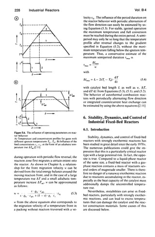
6.2. Parametric Sensith'ity
Parametric sensihvity IS the property typical
of all highly exothermiC reactions with high acti-
vation energy: small changes In the operatmg
parameters can lead to large changes 10 the max-
imum temperature and yield. The reason IS the
exponential dependence of the reaction rate on
temperature (Arrhenius law). Figure 6.1 ~hows
calculated temperature profiles for partial oxida-
tion in a wall-cooled. fixed-bed reactor tube of
typical dimensions. In Figure 6.1 A only the
maIO reaction IS considered. while 10 Figure 6.1 B
the total combustion to CO2 and water IS addi-
tionally taken into account. Since conSiderably
more heat is liberated In the total combustIOn
than in the desired maIO reactIOn. the sensitivity
IS increased conSiderably. As a measure of the
parametric sensitivity. Figure 6.1 C shows the
change in the maximum temperature Via the
coohng temperature for case B. The sensitivity is
only moderate at low coohng temperatures.
whereas above T, = 343 C small changes In
T, and also 10 other parameters such as
throughput. feed concentratIOn. or pressure
lead to large changes in reactor behavIOr. Due to
the unaVOidable differences between mdivldual
tubes. multltubular reactors cannot be operated
m the range of high parametnc sensitivity. In thiS
case the coolmg temperature must be lowered to
ca. 340 C. and the tubes made longer to give a
good conversIOn. This example emphaSizes the
reqUirement. discussed 10 Chapter 4. for makmg
the conditIOns m the tubes of the tube bundle and
m the cooling circuit as umform as pOSSible to
aVOId premature runaway reactIOn m indiVidual
tubes.
In the literature there are numerou~ run-
away cntena with which operating ranges of
high parametric sensitivity can be precalculated
for known reaction kmetlcs [6.1] [6.3). In prac-
Fixed-Bed Reactors 229
tice. however. these parameters are of only limit-
ed Importance because they rarely take mto ac-
count the pecuharitles of mdivldual cases. Sen~l
tive reactions such as partial OXidatIOn and
partlUl hydrogenatIOn are therefore generally
tested 10 single-tube reactors of the same dimen-
sions as those in the subsequent multltubular re-
actor. ThiS allows the range of parametnc sensI-
tiVIty to be determmed directly. RecalculatIOn of
the results for other tube diameters IS only POSSI-
ble to a hmlted extent due to the uncertamties In
the quantificatIOn of the heat-transfer parame-
ter~ (see SectIOn 2.3).
An operatmg fixed-bed reactor can enter the
region of high parametric ~en~ltlVlty through
changes 10 the catalyst propertie~ or operatmg
conditions. Initially a few particularly sen~ltle
tubes of the bundle will runaway. I.e. the reac-
tion changes. for example. from a ~elective par-
tial OXidatIOn to a total combu~tlon. and the tem-
perature rlse~ rapidly. In a multltubular reactor
WIth thou~ands of tubes every tuhe cannot be
eqUIpped with temperature-profile measure-
ments: It is therefore likely that thl~ runaway WIll
remam undetected. especlUlly if It involves only a
few tuhe~. Although temperatures > 1000 C
can often be reached In the cataly~t dUring ,uch
runaay~. they are generally safe proVIded the
tuhe I~ surrounded by heat-transfer medium Be-
cause of the good heat transfer to the flUId the
tuhe temperature remam~ close to that of the
heat-tran~fer medium. and melting of the tuhe
docs not occur. The mo~t certain method of de-
tecting a runaway IS on-hne analYSIS of a product
formed 10 the runaway reaction. For example.
CO2 can he momtored 10 the off-gas dunng the
runaway-sensitive syntheSIS of ethylene OXide. If
Its concentration increases above a speCIfied lim-
it. the reactor must he shut down and for a cer-
tam penod cooled to a lower cooling tempera-
ture hefore operation IS recommenced. The
reason why lowermg the coohng temperature
dunng operatIOn does not extmgUlsh the run-
away reactIOn is dIscussed helow.
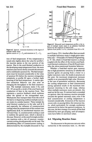
6.3. Multiple Stationary States
The term parametric ~ensltl'lty applle, when.
accordmg to FIgure 6.1 D. a ~tate quantIty (Tmu)
IS a ~mgle-valued functIOn of a control quantIty
(T,) However. In the runaway examples dIS-
cussed III SectIOn 6.1 thIS dependence can also he
multiple valued. Then the runaway occur~ not m](https://image.slidesharecdn.com/fixedbed-200303072027/85/Fixed-bed-31-320.jpg)
![230 Industrial Reactors Vol. B4
0 ®
1000 1000
344(
600
f t 600
u
0
);'
'..:
'..:
400
200 L-...I..--'---'---':--.L..--:'.
o 0.5 1.0 1.5 2000 0.5 1.0 1.5
Reactor length, m_ Reactor length, m_
©
f
60
..,.00<1>
70 /0
60"/ :
50
hocP
40 _o__o~O"'o..o
30L--L--...I..-~--~--'
300 320 340
Te,O(_
1400
1200
1000 t
600 u
0
600
M
~
....E
400
200
®
1100
900
f 700 Main reaction
u ./0 ....
....":: 500 ........ ........
........"No reaction
300 ..-
400 500 600
Tc,O(_
Figure 6.1. Parametnc sensitivity or a partial oxidation reaction m a fixed-bed reactor or typical dimensions as a runctlOn
or the coolant temperature Tc with T(z = 0) = Tc
A) Temperature profile over reaction length (main reactIOn only); B) Temperature profile mcluding total OXidatIOn as Side
reaction. C) Maximum temperature Tm.. and Yield as a runCtlOn orcoolant temperature Tc in case B: 0) Tm.. as a runctlon
or Tc ror both cases
a finite range of the control quantity, but on
exceeding a fixed limit Tel' often referred to as
the ignition limit (Fig. 6.2). Between ignition and
extinction ofthe runaway reaction (at Tc = TeE)'
there is a hysteris region in which two stable sta-
tionary states are possible; at least one unstable
intermediate state must lie between them. Vari-
ous causes of multiple stationary states in fixed-
bed reactors are known [6.4], [6.5]. Here, only
the so-called thermal instabilities are discussed.
They occur in exothermic reactions and arise be-
cause the evolution of heat increases exponen-
tially with increasing temperature. while the heat
removal at constant cooling temperature in-
creases only linearly. Thus on exceeding a certain
temperature limit. the heat release increases
more rapidly than the heat removal, and the re-
action ignites. On dropping below a second, low-
er temperature limit. the heat release becomes
less than the heat removal. and the reaction is
extinguished. In fixed-bed reactors. this process
of ignition and extinction is associated with a
local displacement of the main reaction zone.
This can be most readily demonstrated by the
example ofan exothermic reaction in an adiabat-
ic fixed-bed reactor.
Figure 6.3 shows the temperature profile for
the catalytic total oxidation of ethane as a func-](https://image.slidesharecdn.com/fixedbed-200303072027/85/Fixed-bed-32-320.jpg)
![232 Industrial Reactors
perature and concentration profiles established
after a sufficiently long operating time. Howev-
er, in practice it is often more important in which
way and with which velocity these profiles ap-
proach the next stationary state. This dynamic
behavior of fixed-bed reactors with exothermic
reactions exhibits several special features which
are connected with the axial displacement of the
main reaction zone In the form of a so-called
migrating or moving reaction zone. The behav-
ior can be most easily discussed by using the
example of an adiabatic fixed-bed reactor.
Figure 6.4 shows measured temperature pro-
files for the methanation of traces of CO and
CO2 , This reaction is carried out in an adiabatic
fixed-bed reactor during ammonia synthesis gas
production. If the feed concentration is in-
creased, a new main reaction zone forms in the
front part of the reactor, and the temperature
rises here to a new maximum value. At the same
time, the reactor outlet temperature initially
drops below the original value before increasing
to the new final value. This temporary reaction
in the wrong direction is known as wrong-way
behavior. More surprising is the wrong-way be-
havior in the examples of Figure 6.4 B (decrease
in feed concentration) and Figure 6.4C (decrease
in feed temperature). Particularly in the latter
case, the maximum temperature in the fixed bed
initially increases rapidly while the main reaction
zone moves slowly backwards out of the reactor.
An explanation for this behavior in terms of the
heat balance around a migrating combustion
zone was first derived by WICKE and VORTMEYER
[6.11). In a migrating reaction zone that moves
through an adiabatic fixed-bed reactor with ve-
locity I' due to lowering of the feed temperature
to ro (Fig. 6.5), gas !lows from the left into the
reaction zone with velocity v -II' and tempera-
ture ro (v = gas velocity), while from the right
catalyst enters the reaction zone with velocity II'
and temperature ro + LTand reacted gas leaves
with velocity v - I' and the same temperature.
The energy balance for the mIgrating reaction
zone is thus:
r.' A· (v - 1') 'C!c;' cpG ' LTad =
Heat of reactIOn
Introduced and
released WIth the gas
r. . A . (v - 1') . C!G . cpG
. LT
Latent heat taken up
by the gas
+ (1 - r.) . A . I' 'C!• . c, . LT
Latent heat released by
the packing (6.1 )
® T..
SV
=22S0(
=10S80h-1
220 0 05 10
z/L-
@
350
1300
.....:
250
CD
350
1300
w
o
,....... 250
z/L_
z/L_
Vol. B4
to
Figure 6.4. Measured (pOints) and calculated temperature
profiles shOWing the transient of an adlaballC fixed-bed
reactor for the methanatlOn of CO and CO2 [6 to]
A) TranSlllon after Increase In feed concentratIOn; B) Tran-
SllIon after decrease In feed concentrallon; C) TranSItIon
after decrease In feed temperature
SV = 1/, V. (space veloctty)](https://image.slidesharecdn.com/fixedbed-200303072027/85/Fixed-bed-34-320.jpg)
![Vol. B4
I
I
-------+----~-~-------.-
I I
1 Gas: v-~ bking: w
.....TOf-------i"""11----t-----J-
Reaction
zone
z _
Figure 6.S. DerivatIOn of the energy balance In a quasl·sta-
tionary mIgrating reaction zone In a fixed-bed reactor
It follows that for the temperature increase
AT at the reaction front:
AT= AT.d
1 _ (1 - E) . W . es • Cs
(6.2)
E . (v - w) . eG . cpG
Thus for II" > 0 (i.e., reaction zone moving
downstream), the temperature increase of the re-
action front is always larger than the adiabatiC
temperature rise because the entenng gas is heat-
ed by the hot catalyst (which is cooled) and be-
cause of the liberated heat of reaction.
The examples of autothermal reactIOn con-
trol with periodic reversal of the flow direction
(SectIOn 5.2) show that the temperature increase
of the combustion zone can be conserably higher
than the adiabatic temperature rise. According
to Equation (6.2), the temperature increase in the
combustion can even rise to arbitrarily high val-
ues when the denominator approaches zero; i.e.,
the migration velocity reaches the critical limit
Werll :
E' Fl • C G
W . = "G p • l' (6.3)
en' E' eG . cpG + (1 - r.) . es . c,
In this case. the reaction front moves with
exactly the velocity of a temperature front with-
out reactIOn. Ifdispersion effects such as thermal
conduction are neglected. the liberated heat of
reaction can no longer be transported out of the
reaction zone and thus accumulates there.
The migration velocity II" of a reaction front
can generally not be preset from outside. but IS
instead a result of the complex interaction of
material and heat transport WIth the reaction. as
is approximately described by fixed-bed reactor
models. However, there IS one noteworthy ex-
Fixed-Bed Reactors 233
ception, which occurs when the catalyst in the
main reactIOn zone is deactivated WIth exactly
the critical velocity.
In the example of Figure 6.6. this deactiva-
tion was carried out deliberately by addmg a cat-
alyst pOIson (thiophene) to the feed at time ( = o.
This results in a deactivation of the nickel cata-
lyst by irreversible adsorption of thiophene,
whereby the adsorption front moves through the
bed with veloctty 1'. pushing the reaction front
before it. The accidental addition of a catalyst
poison can thus lead to migrating combustion
zones with very hIgh maximum temperatures In
both adiabatic and nonadlabatic reactors, if a
migration veloctty in the cntical range is Imtiat-
ed.
Particularly problematic is catalyst deactiva-
tion due to excess temperature deactivation of
the catalyst because it results in a VIcious circle:
the catalyst IS deactivated m the region of the
main reaction zone due to an excessive maximum
temperature. This leads to a migrating combus-
tIOn zone in which the maximum temperature
rises further. and so on. Impressive examples of
this behavIOr in wall-cooled reactor tubes have
been described by BLAUM [6.13] and EMIG [6.14].
Figure 6.7 shows measured profiles in a bed
of thermally unstable nickel catalyst in the case
of CO OXIdation. Figure 6.8 shows the tempera-
ture profile for vinyl acetate synthesis over ZinC
acetate. Smce the zmc acetate catalyst decom-
poses above 500 K. the result is a reaction front
that moves downstream. The dip m the tempera-
ture profile (d) clearly indicates deactIvation at
the posttion of the onginal temperature maxl-
220
200
180
1
160
140
120
~ 100
.....- 80
60
40
z/L_
Figure 6.6. MIgrating reactIon front In an adlabattc fixed-
bed reactor due to intentIOnal cataly,t pOI,onlng (h}dro-
genatton of benLene over Olckell 16 12J
At I = O. a cataly,t pOlson thiophene IS added to the feed](https://image.slidesharecdn.com/fixedbed-200303072027/85/Fixed-bed-35-320.jpg)
![234
700
600
1
500
u
o
,...: 400
300
Industrial Reactors
161
121
0.2 0.4 0.6 0.8 10
z/L-
Figure 6.1. Mlgratmg combustion zone m the case of CO
oxidatIOn over nickel. caused by thermal deactivation of
the catalyst [6.13)
640
600
I560
""
520
...... 480
440
0 0.2 to
z/L-
Figure 6.8. Migrating reaction front during the synthesIs
of vmyl acetate over zmc acetate, caused by thermal dam·
age to the catalyst [6.14)
a) 60 mm; b) 75 mm; c) 100 mm; d) 165 min
mum. In the past, this was sometimes cited as a
good example of parametric sensitivity. The
above discussion, however, shows that the cause
of the "runaway" reaction should rather be at-
tributed to the dynamic influence of the migrat-
ing combustion zone.
6.5. Safety Aspects
Because of the small mass storage capacity
compared to liquid-phase reactors. the danger of
sudden reaction ofaccumulated reactants in gas·
pha~e fixed·bed reactors is low. Leaving out the
peculiarities of individual cases. the following
Vol. 84
safety risks can be assumed for fixed-bed reac-
tors:
1) Leaks which result in the release of large
amounts ofgas or vapor and the formation of
explosive clouds
2) Leaks resulting in release of large amounts of
liquid heat-transfer media (oils, salt melts)
3) Occurrence of ignitable or decomposable gas
mixtures in the reactor
4) Melting of the reactor due to a runaway rea(-
tion
The safety aspects of liquid heat-transfer me-
dia are discussed in Section 4.3.1. Ignitable gas
mixtures can arise particularly during partial ox-
idation reactions. They are especially critical
where large packing-free volumes are present.
This is the case in the inflow and outflow hoods
of the reactor, while in the reactor tubes the cat-
alyst packing dampens the propagation of a
flame front due to its heat capacity. Complete
avoidance of ignitable mixture is generally not
possible in partial oxidations because at least
during mixing of the gas streams prior to the
reactor the ignition limit is exceeded locally.
Nevertheless, in the past, operation of fixed-bed
reactors with ignitable mixtures was avoided, ei-
ther by dilution with inert gas or by operating in
the nonstoichiometric range. The former re-
quires additional efforts for heating, cooling,
and separation of the inert gas, while the latter
gives only low conversions of the reactants in a
single pass. New developments in partial oxida·
tion therefore aim for stoichiometric operation
in the ignitable range [6.17]. A prerequisite for
this is pressure-resistant construction with check
valves and flame barriers so a possible that igni-
tion is confined to the interior of the reactor.
Melting of reactor tubes during runaway re-
action is only to be feared in multitubular reac-
tors if the respective tube is not surrounded by
heat-transfer medium. Thus. appropriate design
must ensure that running dry of reactor tubes
cannot occur. In the case of corrosive reaction
gases, apparatus for the detection ofleaks caused
by corrosion must be provided, particularly
when pressurized or boiling water is used as
coolant.
If the coolant circulation is interrupted dur-
ing an exothermiC reaction. the reactor must be
shut down. Nevertheless, the heat storage capac-
ity of the catalyst and the heat-transfer medium
surrounding the tubes allows sufficient reac-
tion time for controlled shutdown of the reactor.](https://image.slidesharecdn.com/fixedbed-200303072027/85/Fixed-bed-36-320.jpg)
![Vol. B4
This is shown by simulation calculations for a
multitubular reactor (Fig. 6.9) with a partial oxi-
dation reaction. It was assumed that at t = 0
either the circulating pump fails or that the regu-
lating valve in the pipe to the steam generator
closes. As can be seen in Figure 6.9, there is a
time span of200 or 350 s, respectively before the
maximum temperature in the catalyst reaches
unpermissably high values.
In large-volume adiabatic fixed-bed reactors,
local temperature maxima (hot spots) can form
due to nonuniform distribution of the flow or
inhomogeneities in the catalyst packing. They
1.9
15
®
I
t--Valve closure m,-O(at '=01
j Pump failure v, -0 (at '=01
,,.,
'/''"1:
/' '
": : ..-----".-, 1 _---- t.m,=-25%
I~~~ ___ - - - - - - - -
.'T--___ _
:: T---
, 1 t.m,=+25%, ,, ,
o : :500 1000 1500 2000
200 350
t.s_
025 050
z/L_
075 100
Figure 6.9. EfTect of disturbances In the coolant Circuit of
a multitubular reactor (Fig 610) with a partial OXidatIOn
reaction [6 15]
A) Profile of maximum temperature With lime after change
of the valve poSitIOn (~J. after pump failure It, -+ 0).
and after valve closure (m, -+ 0); B) Temperature profile
after failure of the coolant clrculallon pump
Fixed-Bed Reactors 235
can be intensified by front migration phenomena
(Section 6.4) and can lead to thermal damage of
the reactor. This is particularly true of runaway-
prone reactions such as partial hydrogenation
with a large excess of hydrogen, which can
change from selective hydrogenation to com-
plete methanation. This can be detected by on-
line analysis of methane in the product.
6.6. Control of Fixed-Bed Reactors
The control of fixed-bed reactors for chemi-
cal synthesis generally only involves maintaining
the operating conditions at the optimum values.
For runaway-prone reactions, this is supple-
mented by an extensive measurement and con-
trol system with built-in redundancy for giving
alarm and shutting down the reactor. Slow
changes in catalyst activity during multistage
adiabatic reactors are corrected by "manual" ad-
justment ofthe set value for the feed temperature
of each stage in multitubular reactors or by the
adjustment of the heat-transfer medium temper-
ature. The target is usually to keep the desired
conversion constant. Mass flow control. feed
stoichiometry control, control of the total pres-
sure (generally in the reactor outlet), as well as
feed temperature and heat-transfer medium tem-
perature control are therefore the most impor-
tant automatic control circuits in fixed-bed reac-
tors.
In the following, some special points con-
cerning the cooling temperature control ofmulti-
tubular fixed-bed reactors are considered. In a
multitubular reactor with molten-salt cooling
(Fig. 6. t0) the cooling temperature is controlled
by a control unit in the connecting channel to the
steam generator. In thiS way, varying amounts of
colder salt melt can be introduced into the circu-
lation system, with effective mtxmg taking place
In the circulating pump. This coohng circuit can
be unstable [6.3]. Since the reaction rate or liber-
ated heat QE increases exponentially wtth m-
creasing cooling temperature, while the heat re-
moved in the steam generator Q" increases only
linearly, the conditIOns shown in Figure 6. t t
may occur in the desired state. On a slight in-
crease of the cooling temperature above Te, ... '
the coohng circUlt warms up since QF > Q", and
on dropping slightly below Tc:, ... cools down be-
cause Q" > QE' Because of the large thermal in-
ertia, however, the unstable operatmg pOint can
easily be stabIlized vta the control Te (Ftg. 6.10).](https://image.slidesharecdn.com/fixedbed-200303072027/85/Fixed-bed-37-320.jpg)
![236
T T,
Reactor
Industrial Reactors
Circulation
pump
Water
Cooler
(evaporator)
Figure 6.10. Temperature control In a fixed-bed reactor
with molten-salt cooling
Ts Tc.set
re-
Figure 6.tt. Heat generation QF and heat removal QA for
the cooled mullltubular reactor of FIgure 6 0 as a functIOn
of coolant temperature [6.3)
To obtain optimum conversion, attempts are
usually made to operate with a cooling tempera-
ture so high that a previously determined maxi-
mum temperature in the reactor is just reached
but not exceeded. The maximum temperature
can be measured by equipping several tubes of
the bundle with multiple thermoelements which
allow simultaneous measurement of. for exam-
ple, 10-20 temperatures along the tube length.
This allows regulation of the maximum tempera-
ture. which influences the set point of the cooling
temperature in a cascade cIrcuit. However, deter-
mining the maximum temperature from various
Vol. 84
discrete measurement points is not trivial [6.16].
Therefore, methods for the model-based mea-
surement techniques should be used here.
In the case ofcooling with a boiling medium,
a multitubular reactor generally has the structure
shown in Figure 6.12. The cooling temperature
here corresponds to the boiling temperature in
the vapor drum, which is controlled by a control
unit in the saturated vapor line. The cooling tem-
perature control is thus performed by controlling
the saturated vapor pressure in the vapor drum.
The dynamics of the natural convection cooling
circuit has a particular effect on the behavior of
this control loop. Thus rapid lowering of the
cooling temperature via the drum pressure by
opening the saturated vapor valve leads to in-
creased boiling of the coolant in the circuit. Ifthe
liquid boils into the downpipe. the natural circu-
lation is temporarily interrupted. Furthermore.
the increase in volume associated with boiling
pushes liquid into the vapor drum, which can
result in liquid entering the vapor line. This is
discussed in detail in [6.15].
If the fixed bed to be regulated is part of a
supply or off-gas treatment plant that is subject
to large variations in feed concentration and
throughput, then a fixed control is difficult.
0
0
•0
o.
'0 0
·0 0,
.00
0
0
0
..p'
0
0
0
0
0
_0 _
Coolant
liquId coolant
(feed)
Figure 6.12. Multllubular reactor wIth evaporallve coohng](https://image.slidesharecdn.com/fixedbed-200303072027/85/Fixed-bed-38-320.jpg)
![Vol. B4
mainly because of the complex wrong-way be-
havior (see Section 6.4). Hence, in practice a cat-
alyst with a wide operating range is used and the
reactor is made larger.
7. References
[2.1] L. Riekert, Appl. Calal. 15 (1985) 89- 02.
[2.2] V. Kottke, H. Blenke: "Verfahren zur Bestimmung
iirthcher Stoff- und Warmeiibertragung an behebig
geformten Oberflachen," Verfahrenslechmk (Mam:)
16 (1982) 504-509.
[2.3] Verem Deutscher Ingemeure: VDI-Warmeallas, 5th
ed., Section Gh, VOl-Verlag, Diisseldorf 1988.
[2.4] E Tsotsas: "Uber die Warme- und Stoffiiber-
tragung m durchstromten Festbetten," VDI-
Forlschr. Ber.. ReIhl' 3, 1990, no. 223.
[25] G. Gaiser, V. Kottke' "Warme- und Stoffiibergang
in Katalysatoren mit regeimalliger Formgebung,"
Chem.lng Tech 61 (1989) 729- 731.
[2.6] R. K. Shah, A. L London "Lammar Flow Forced
Convection m Ducts," Advances in Heal Transfer,
suppl. I, Academic Press, New York 1978
[2.7] S. Quest, D. Mewes "Der Emf1ull des Temperatur-
feldes auf den Stoffaustausch m lammar durch-
stromten Rohrreaktoren," Warme Sioffuberirag. 32
(1988) 355-363.
[28] G. Gaiser, V. Kottke: "Flow Phenomena and Local
Heat and Mass Transfer m Corrugated Passages,"
Chem. Eng Technol 12 (1989) 400 405
[2 9] Verem Deutscher Ingenieure. VDI· WeIr/ileallas, Sec-
tIOn Le I, VOl-Verlag, Dusseldorf 1988.
[2.10] Verem Deutscher Ingemeure: VDI- Warmeal/a." Sec-
tIOn Mh I, VOl-Verlag, Diisseldorf 1988
[2 II] G. Eigenberger, U Nieken "Katalytlsche Abluft-
reimgung' Verfahrenstechmsche Aufgaben und neue
Losungen," Chem. Ing. Tech 63 (1991) 781 791
[2 12] D. Vortmeyer, P Wmter. "Verbesserung der Analy-
se von Festbettreaktoren durch die Beruckslchtl-
gung von Porosltiits- und Stromungsvertcllung,"
Chem Ing. Tech. 55 (1983) 312 313
[2.13] T. Daszkowskl, G Eigenberger. "A Reevaluation of
FlUId Flow, Heat Transfer and Chemical Reaction
m Catalyst Filled Tubes," ehem Eng SCI 47 (1992)
2245 2250
[3 I] U Zardl et al. "A Novel Reactor DeSign for Am-
moma and Methanol S)ntheSls," /I' Intern Confer·
ence Fertlh:er Technolo!!.. London 1981, Hrdrocar·
bon Proces.' (1982) 129-133
[3.2] "Umwelttechmk, Sekundarmallnahmen zur Mm-
derung der NO,-Emlsslon," Slemmuller Sch"flen-
reIhl', L + C, Stemrniiller, 1985
[4.1] C B Allen, G J Janz "Molten Salts Safety and
HaLards. an Annotated Blbhography," J Ha:ard
Maler. 4 (1980) 145-175.
[42] G. Elgenberger, W. Ruppel "Probleme der Modell-
bildung bel techmschen Festbettreaktoren," Chem
Ing Tech. 57 (1985) 181 190
[4.3] A. StankieWICZ: "Advances m Modelhng and De-
Sign of Multltubular Fixed-Bed Reactors," Chem
Eng Tech 12 (1989) 113 130,170 175
[44] M S. G Cnstma et al "Modelling Multltubular
CatalytiC Reactors the Influence of Shell Side
Flow," Chem Eng SCI. 47 (1992) 2565 2570
Fixed-Bed Reactors 237
[4.5] T. F. Degnan, 1. Wei' "The Co-Current Reactor
Heat Exchanger," AIChE J. 2S (1979) 338 -- 344.
[4.6] A. S Lopez, H I. de Lasa, 1. A. Porras: "Paramet-
nc SensitiVity of a Fixed-Bed Catalytic Reactor,"
Chem. Eng Sci. 36 (1981) 285-291
[4.7] D. O. Borio, V. Bucala, 1. A. Orejas, J A Porras
"Cocurrently Cooled Fixed Bed Reactors A Simple
Approach to Optimal Coohng Design," MChE J. 35
(1989) 1899-1902.
[48] 1. C Pirkle, I E. Wachs: "Activity Profihng m Cata-
lytic Reactors," Chem. Eng. Progr. (1987) 29 34.
[4.9] P. H. Calderbank, A. D. Caldwell, G. Ross "The
Diluted Catalyst Fixed Bed Reactor for ExothermiC
CatalytiC ReactIOns," ehemie el Induslr/('·Geme
ChimIque 101 (1969) 215 - 230.
[4.10] G. Eigenberger: "Practical Problems m the Mod-
elling of Chemical Reactions m Fixed Bed Reac-
tors," Chem. Eng. Process. 18 (1984) 55-65
[4.11] E. Klapp' Apparale- und Anlagentechmk, Spnnger-
Verlag, Berlm 1980
[412] Verem Deutscher Ingenieure: VDI-Wiirmeallas, Sec-
tIOn Gf. LD, VOl-Verlag, Diisseldorf 1988
[4.13] U Lahne, R Lohmiiller "Schiittschlchtreaktoren
mit gewlckelten Kiihlrohren, eme konstruktlve Neu-
entwlcklung zur Durchfiihrung exothermer katalytl-
scher Prozesse," Chem Ing Tech 58(1986)212 215
[414] Deggendorfer Werft, DE 2207166,1972 (0 Wanka
et al)
[4.15] Deggendorfer Werft, DE 2201528,1972 (0 Wanka
et al.).
[4 16] P Gnmm "S.. Years Successful Operation of
Lmde Isothermal Reactor," Lmde Reporl.. on SCI-
,'nee and Technology 49 (1991) 57 59
[5 1] G. K Boreskow, G A. Bummovlch, Y S Matros,
A A Ivanov' "CatalytiC Processes Carned Out Un-
der Non-Steady-State Conditions S"ltchmg the DI-
rection of the Feed," Kmetlka I Katahz 23 (1982)
402-406,lnt Chem Eng 22 (1982) 335 342
[52] Y. S Matros "Performance of CatalytiC Proce,ses
under Unsteady Conditions," ehem Eng SCI 45
(1990) 2097 2102
[5.3] Y S Matros "CatalytiC Processes under Unsteady-
State ConditIOns," Slud'e< m Surface Sc/('nce and
Calalys.." vol 43, ElseVier, Amsterdam 1989
[6 1] G. F Froment. Front ehem ReaAI Eng 1 (1984)
pp 12 38
[0.2J M Morbidelll, A Varma "Parametnc SenSltlvlt~
10 FIxed-Bed Cdtalytlc Reactor," AIC/OE J. 32 (1986)
297 306. Ch<'l>1 Eng S" 46 (1991) 3330 3332
[63] G Eigenberger, H Schuler "Reactor Stablhty dnd
Safe ReactIOn Engmecnng," Chem Ing Tn /0 58
(1986) 655 665,lnl C/oem Enx 29 (1989) 12 25
[64] G Elgenberger "Stab,llldt und Dynamlk hetero-
genkatalytoscher RedktlOnssy'teme," C/o,'m IlIg
Tel'/o SO (1978) 924 933
[65] K F Jen,en, W H Ray. "The Bifurcation BehdVlor
of Tubular Reactof'." Chem Eng S" 37 (19X2)
199-222
[6 6] 0 Kalthoff, D Vortmeyer Ch,'m Eng S" 35
(1980) 1637 1643
[67] G Flgenberger "Influence of the Wall on the D~
namlc BehaVIOr of Homogeneous Tubular Reactof'
With a Highl) ExothermiC ReactIOn:' C/ot'lll Sa
133 (1974) 477 488
[68J G Eigenberger "Zur Modellblldung und Dyndmlk
des homogenen Rohrreakto,,:' Chem IIIIi Tt', /0 46
(1974) II 19](https://image.slidesharecdn.com/fixedbed-200303072027/85/Fixed-bed-39-320.jpg)
![238 Industrial Reactors
[6.9] G. Eigenberger: "On the Dynamic Behavior of the
Catalytic Fixed-Bed Reactor m the Region of Multi-
pie Steady States - II," Chern. Eng. Sci. 278 (1972)
1917-1924.
[6.10] H. von Doesburg, W. A. de Jong: "Transient Behav-
ior of an Adiabatic Fixed-Bed Methanator," Chern
Eng. Sci. 31 (1976) 45-58.
[6.11) E. Wicke, D. Vortmeyer: "Ziindzonen heterogener
ReaktlOnen m gasdurchstromten Komerschlchten,"
Ber. Bunsenges. 63 (1959) 145-152.
[6.12] T. H. Price, 1. B. Butt: "Catalyst Poisonmg and
Fixed-Bed Reactor Dynamics II," Chern. Eng. SCI.
32 (1977) 393-412.
[6.13] E. Blaum· "Zur Dynamik des katalytischen Fest-
bettreaktors bei Katalysatordesaktivierung," Chern.
Eng. Sci. 29 (1974) 2263 - 2277.
Vol. 84
[6.14] G. Emig, H. Hofmann, U. Hoffmann, U. Fiand·
"Expenmental Studies on Runaway of CatalytiC
Fixed-Bed Reactors," Chern. Eng. SCI. 85 (1980)
249-257.
[6.15] G. Elgenberger· "Modelling and Computer Simula-
tion as Aids for Safe Reactor Operation," Chern
Ing. Tech. SI (1979) 1105-1110; Int. Chern Eng. 3
(1980) 211-216.
[6.16) G. Eigenberger: "Temperaturregelung von chemi-
schen Rohrreaktoren mit stark exothermer Reak-
tion," Regelungstechnik (1975) 118-126.
[6 17] Deggendorfer Werft, Reactor Systems and their Ad-
vantages, Technical information, May 1989.](https://image.slidesharecdn.com/fixedbed-200303072027/85/Fixed-bed-40-320.jpg)


