The document presents a fire fighting robot system designed using Arduino technology, which autonomously detects and extinguishes fires. It incorporates sensors like a fire sensor and a water level sensor, along with motors for movement and a water pump for spraying water to extinguish flames. The system's modular design allows for independent task execution, improving efficiency in emergency situations where human intervention is risky.


![International Journal of Trend in Scientific Research and Development (IJTSRD) @ www.ijtsrd.com eISSN: 2456-6470
@ IJTSRD | Unique Paper ID – IJTSRD27854 | Volume – 3 | Issue – 5 | July - August 2019 Page 2105
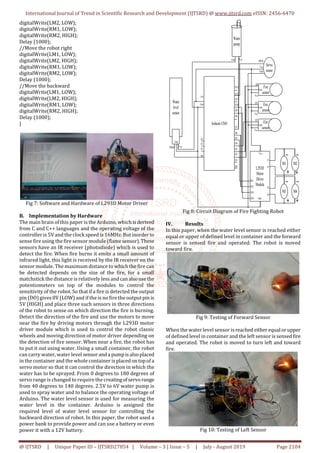
When the water level sensor isreached eitherequal orupper
of defined level in container and the right sensor is sensed
fire and operated. The robot is moved to turn right and
toward fire.
Fig 11: Testing of Right Sensor
When the water level sensor is reached under the defined
level of sensor in container, the robot is moved to backward.
Fig 12: Testing of Backward Direction
V. Discussion
This paper is discussed about fire fighting robot system.The
extensive use of microcontrollers ensured the integration
step to be simpler. There were still some problems at
integration step but they were solved easily because
debugging is done on each module. Therefore, final modelof
the robot successfully finds “fire” and reach it without
running into obstacles. Throughout the paper, technical
knowledge was put to practical use and hence learnt many
technical skills, and aims to avoid fire accidents and also
prevent manual intervention of fire extinguishing.Therobot
performs its operation under adverse circumstances
effectively.
VI. Conclusion
In conclusion, approach of modular design strategy was a
good solution in implementing the fire fighting robot as it
made it easier for individuals to work on their tasks
independently. The fire fighting robot employs Arduino
technology to control the directions of the robot.This design
is the fire detection system using fire sensor that is capable
of sensing the flame of wavelength range 760nm to 1100nm
and the sensing range depends on the sensitivity and varies
from 10cm to 50cm. The robot can operate in the
environment which is out of human reach in veryshorttime,
the delay employed minimum time after the fire is detected
to extinguish.
VII. REFERENCES
[1] Anonymous: “Fire Fighting System”, (2018).
https://www.slideshare.net/NaqashKazmi/final-year-
project-on-fire-fighting-systems-64012615
[2] Anonymous: “Arduino UNO”, (2018).
https://www.trossenrobotics.com/p/arduino-
uno.aspx
[3] Anonymous: “Fire Sensor”, (2018).
https://www.instructables.com/id/Arduino-Modules-
Flame-Sensor
[4] Anonymous: “Servo Motor”, (2018).
https://components101.com/servo-motor-basics-
pinout-datasheet
[5] Anonymous: “L293D Motor Driver”, (2018).
https://www.campuscomponent.com
[6] Anonymous: “Water Pump”, (2018).
https://www.seeedstudio.com/6V-Mini-Water-Pump-
p-1945.htm
[7] Anonymous: “Water Level Sensor”, (2018).
http://osoyoo.com/2017/09/27/arduino-lesson-
water-sensor/#2.2
[8] Aswinth, R.: “Fire Fighting Robot Code”, December,
(2017).
https://www.circuitdigest.com/microcontrollerproject
s/arduino-fire-fighting- robot-code.com
[9] Stafford, M.: “Fire Fighting Robot.pdf”,October,(2017).
https://www.researchgate.net/publication/31761094](https://image.slidesharecdn.com/403firefightingrobotsystem-190917124832/85/Fire-Fighting-Robot-System-5-320.jpg)


![Human presence detection based room light controller using pir2.pptx [repaired]](https://cdn.slidesharecdn.com/ss_thumbnails/humanpresencedetectionbasedroomlightcontrollerusingpir2-160418083434-thumbnail.jpg?width=640&height=640&fit=bounds)