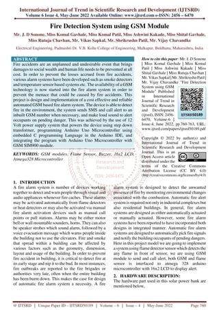
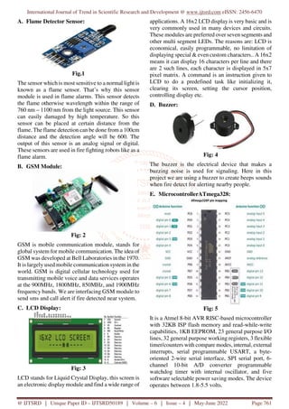
The document discusses the design and implementation of a cost-effective and reliable GSM-based fire alarm system aimed at preventing fire accidents, which can cause significant loss to life and property. The system utilizes an Arduino Uno microcontroller integrated with a flame sensor, GSM module, LCD display, and a buzzer to provide alerts through SMS and audio signals when fire is detected. This automated approach is intended to ensure timely notification to occupants and enhance safety in both residential and industrial settings.
![International Journal of Trend in Scientific Research and Development @ www.ijtsrd.com eISSN: 2456-6470
@ IJTSRD | Unique Paper ID – IJTSRD50189 | Volume – 6 | Issue – 4 | May-June 2022 Page 763
6. CONCLUSION
Fire accident claims the lives of innocent people
around the world every single day. A small amount of
fire is able to damage a huge part of a society.
Although heat detectors and fire alarms alert people
of danger, they often have few choices other than
escaping from a building and calling the fire
department. In this paper, it can be concluded that the
proposed system can provide a secure, safe, and
efficient way for preventing or combating fire
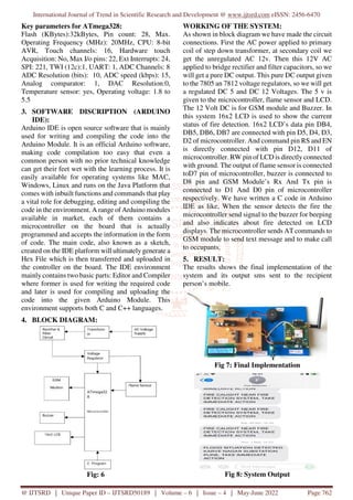
accident. This was achieved by the implemention of
12 V power supply system that powers the device,
programming Arduino Uno Microcontroller using
C++ programming Language in the Arduino software
platform, and integrating the program med Arduino
Uno Microcontroller with GSM SIM800 module. The
GSM SIM800 module was incorporated in the system
in order to send sms and call to the occupant of the
building on any impeding danger so as to combat the
situation on time and to prevent losses.
7. REFERENCES
[1] L. Zhang and G. Wang, ‘Design and
Implementation of Automatic Fire Alarm
System based on Wireless Sensor Works’,
Proceedings of the International Symposium on
Information Processing (ISIP’09), Huangshan,
2009, pp 410-413.
[2] O.H. Kwon, S.M. Cho, and S.M. Hwang,
‘Design and Implementation of Fire Detection
System. Advanced Software Engineering and
its Applications’, Hainan Island, 2008, pp.
233236.
[3] J. H. Li, X. H. Zou, and W. Lu, ‘The Design
and Implementation of Fire Smoke Detection
System Based on FPGA’, Proceedings of the
24th Control and Decision Conference,
Taiyuan, 2012, pp 3919-3922.
[4] A Cote and P. Bugbee, ‘Ionization Smoke
Detectors: Principles of Fire Protection’,
National Fire Protection Association, Quincy,
249, 1988.
[5] R.W. Bukowski, R.D. Peacock, J.D. Averill,
T.G. Cleary, N.P. Bryner, W.D. Walton, P.A.
Reneke, and E..D. Kuligowski, ‘Performance of
Home Smoke Alarms Analysis of the Response
of Several Available Technologies in
Residential Fire Settings’, NIST TN 1455-1;
NIST Technical Note 1455-1; 2007, pp. 396.
[6] J. Gerhart, ‘Home Automation and Wiring’
McGraw-Hill Professional, 1999, ISBN
0070246742.
[7] H. Richard, ‘Inside the Smart Home’, Springer,
2003, ISBN 1852336889.
[8] T. Nikola, ‘Method of and apparatus for
controlling mechanism of moving vessels and
vehicles’, United States Patent and Trademark
Office, U.S. Patent 613809, 1898.](https://image.slidesharecdn.com/154firedetectionsystemusinggsmmodule-220804114954-eb30e089/85/Fire-Detection-System-using-GSM-Module-4-320.jpg)