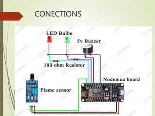
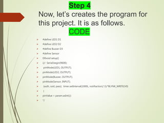
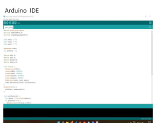
Fire Alarm System
IoT Based Fire Alarm System Using
NodeMCU ESP8266 and Blynk
OBJECTIVE
This project will send an alert whenever it detects
fire and smoke.
It has also connected with a buzzer and an LED which
will act as Audio and visual for indication for alert.
So lets quickly start building IoT based fire security
alarm system using NodeMcu.
Sr. no Required Components Quantity
1. ESP8266 NodeMCU 1
2. Flame Sensor 1
3. 5V Buzzer 1
4. LED Any color 2
5. Breadboard 1
6. Resistor 100Ω 2
7. Jumper cables As per required
8.
ESP8266 NodeMCU
NodeMcu
◦ ESP8266 NodeMCU is an open source IoT platform.
◦ It includes firmware which runs on the low cost Wi-Fi enabled ESP8266
Wi-Fi SoC from Espressif Systems, and hardware which is based on the
ESP-12 module.
◦ It has GPIO, SPI, I2C, ADC, PWM AND UART pins for communication and
controlling other peripherals attached to it.
◦ On board NodeMCU has CP2102 IC which provides USB to TTL
functionality.
◦ In this IoT Fire Alarm, we are using two GPIO pin to get the digital data
from the flame sensor and gas sensor.
Flame Sensor
FLAME SENSOR
 A Flame Sensor is a device that can be used to detect
presence of a fire source or any other bright light sources.
There are several ways to implement a Flame Sensor but the
module used in this project is an Infrared Radiation
Sensitive Sensor.
 The module uses a LM393 comparator chip to provide a
stable digital output signal. This comparator has a driving
ability of 15 mA. This flame detector sensor can be used in
different project including fire alarms and other fire
detecting devices or projects.
Buzzer 5V
Buzzer is a kind of voice device that converts audio model into
sound signal. It is mainly used to prompt or alarm
LED
A light-emitting diode (LED) is a semiconductor device that emits light
when an electric current flows through it.
Resistor
The resistor is a passive electrical component that creates
resistance in the flow of electric current
BreadBoard
A Breadboard is simply a board for prototyping or building
circuits on
Jumper Cables
Jumper cables are simply wires that have connector pins at each
end, allowing them to be used to connect two points to each
other without soldering.
procedure
• Step 1
Firstly, identify all of these components.
• Step 2
Secondly, connect these components in proper
ways as per circuit diagram given below so
that there should not any faults i.e. it would be
errorless there is no chance of errors.
CONECTIONS
Step 4
Now, let’s creates the program for
this project. It is as follows.
CODE
 #define LED1 D1
 #define LED2 D2
 #define Buzzer D3
 #define Sensor
 D0void setup()
 {// Serial.begin(9600);
 pinMode(LED1, OUTPUT);
 pinMode(LED2, OUTPUT);
 pinMode(Buzzer, OUTPUT);
 pinMode(Sensor, INPUT);
 (auth, ssid, pass); timer.setInterval(1000L, notifiaction);*/}/*BLYNK_WRITE(V0)
 {
 pinValue = param.asInt();}
 */
void loop() {
int sensor = digitalRead(Sensor);//
if (pinValue == 1)
{// Serial.println("System is ON");
if (sensor == 1) { digitalWrite(LED2, HIGH);
digitalWrite(LED1, LOW); digitalWrite(Buzzer,
LOW);
}
else if (sensor == 0) {//
Blynk.notify("WARNING! A fire was detected");
digitalWrite(LED2, LOW); digitalWrite(LED1,
HIGH); digitalWrite(Buzzer, HIGH); }// } else
if (pinValue == 0)
{// Serial.println("System is OFF"); }
Step 5
Now select board and port, Afterward, upload
this code to the NodeMcu board.
 Click on Tool then select Board NodeMcu 1.0 (ESP-12E
Module)
 Then click on ESP8266 Board(3.0.0)
 Then click on NodeMcu 1.0(ESP-12E Module)
 Now choose port “COM2” ,and then upload it.
Arduino IDE
Conclusion
A fire alarm is a device that detects the presence of fire
and atmospheric changes relating to smoke.
The fire alarm operates to alert people to evacuate a
location in which a fire or smoke accumulation is present.
When functioning properly, a fire alarm will sound to
notify people of an immediate fire emergency.
This distinct sound exists to allow the notification to be
heard The fire alarm constructed by this project work is
reliable at low cost.
THANK YOU

FIRE ALARM SYSTEM PPT.pptx

  • 1.
    Fire Alarm System IoTBased Fire Alarm System Using NodeMCU ESP8266 and Blynk
  • 2.
    OBJECTIVE This project willsend an alert whenever it detects fire and smoke. It has also connected with a buzzer and an LED which will act as Audio and visual for indication for alert. So lets quickly start building IoT based fire security alarm system using NodeMcu.
  • 3.
    Sr. no RequiredComponents Quantity 1. ESP8266 NodeMCU 1 2. Flame Sensor 1 3. 5V Buzzer 1 4. LED Any color 2 5. Breadboard 1 6. Resistor 100Ω 2 7. Jumper cables As per required 8.
  • 4.
  • 5.
    NodeMcu ◦ ESP8266 NodeMCUis an open source IoT platform. ◦ It includes firmware which runs on the low cost Wi-Fi enabled ESP8266 Wi-Fi SoC from Espressif Systems, and hardware which is based on the ESP-12 module. ◦ It has GPIO, SPI, I2C, ADC, PWM AND UART pins for communication and controlling other peripherals attached to it. ◦ On board NodeMCU has CP2102 IC which provides USB to TTL functionality. ◦ In this IoT Fire Alarm, we are using two GPIO pin to get the digital data from the flame sensor and gas sensor.
  • 6.
  • 7.
    FLAME SENSOR  AFlame Sensor is a device that can be used to detect presence of a fire source or any other bright light sources. There are several ways to implement a Flame Sensor but the module used in this project is an Infrared Radiation Sensitive Sensor.  The module uses a LM393 comparator chip to provide a stable digital output signal. This comparator has a driving ability of 15 mA. This flame detector sensor can be used in different project including fire alarms and other fire detecting devices or projects.
  • 8.
    Buzzer 5V Buzzer isa kind of voice device that converts audio model into sound signal. It is mainly used to prompt or alarm
  • 9.
    LED A light-emitting diode(LED) is a semiconductor device that emits light when an electric current flows through it.
  • 10.
    Resistor The resistor isa passive electrical component that creates resistance in the flow of electric current
  • 11.
    BreadBoard A Breadboard issimply a board for prototyping or building circuits on
  • 12.
    Jumper Cables Jumper cablesare simply wires that have connector pins at each end, allowing them to be used to connect two points to each other without soldering.
  • 13.
    procedure • Step 1 Firstly,identify all of these components. • Step 2 Secondly, connect these components in proper ways as per circuit diagram given below so that there should not any faults i.e. it would be errorless there is no chance of errors.
  • 14.
  • 15.
    Step 4 Now, let’screates the program for this project. It is as follows. CODE  #define LED1 D1  #define LED2 D2  #define Buzzer D3  #define Sensor  D0void setup()  {// Serial.begin(9600);  pinMode(LED1, OUTPUT);  pinMode(LED2, OUTPUT);  pinMode(Buzzer, OUTPUT);  pinMode(Sensor, INPUT);  (auth, ssid, pass); timer.setInterval(1000L, notifiaction);*/}/*BLYNK_WRITE(V0)  {  pinValue = param.asInt();}  */
  • 16.
    void loop() { intsensor = digitalRead(Sensor);// if (pinValue == 1) {// Serial.println("System is ON"); if (sensor == 1) { digitalWrite(LED2, HIGH); digitalWrite(LED1, LOW); digitalWrite(Buzzer, LOW); } else if (sensor == 0) {// Blynk.notify("WARNING! A fire was detected"); digitalWrite(LED2, LOW); digitalWrite(LED1, HIGH); digitalWrite(Buzzer, HIGH); }// } else if (pinValue == 0) {// Serial.println("System is OFF"); }
  • 17.
    Step 5 Now selectboard and port, Afterward, upload this code to the NodeMcu board.  Click on Tool then select Board NodeMcu 1.0 (ESP-12E Module)  Then click on ESP8266 Board(3.0.0)  Then click on NodeMcu 1.0(ESP-12E Module)  Now choose port “COM2” ,and then upload it.
  • 18.
  • 19.
    Conclusion A fire alarmis a device that detects the presence of fire and atmospheric changes relating to smoke. The fire alarm operates to alert people to evacuate a location in which a fire or smoke accumulation is present. When functioning properly, a fire alarm will sound to notify people of an immediate fire emergency. This distinct sound exists to allow the notification to be heard The fire alarm constructed by this project work is reliable at low cost.
  • 20.