Downloaded 14 times

![52
REFERENCE
13.1 WEBSITES:
www.atmel.com
www.datasheet.com
www.technovelgy.com
www.engineersgarage.com
www.eletroniczone.com
http://www.alcoholbreathanalyzers.in
13.2 PATENTS & BOOKS:
[1] Zhang Xin-long_Forensic medical discussion of drunken driving and
traffic accidents [J]_Road Traffic Management_2007_12_3_60-
61.l
[2] Zhu Yi-duo The drunk-driving measurement and control system based
on multisensory [J]_Journal of Wuhan Jiao tong Polytechnic_2011_13
_1_78-80
[3] The 8051 Microcontroller And Embedded System Using Assembly
And C By Muhammad Ali Mazidi (2nd
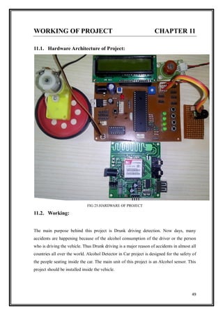
Edition)](https://image.slidesharecdn.com/8semfinalreportprintcopy1-190221185852/85/8-sem-final-report-print-copy-1-52-320.jpg)


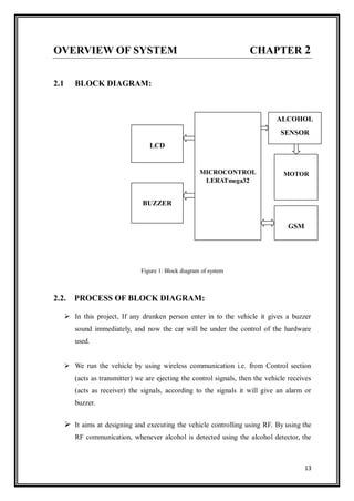
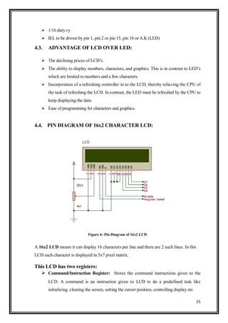
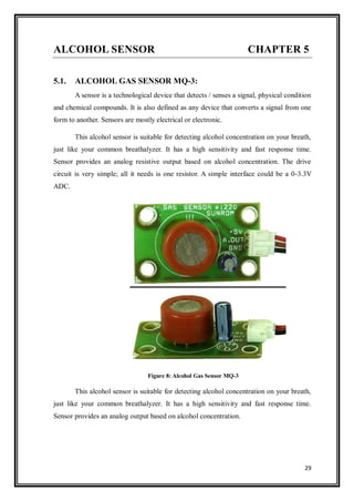
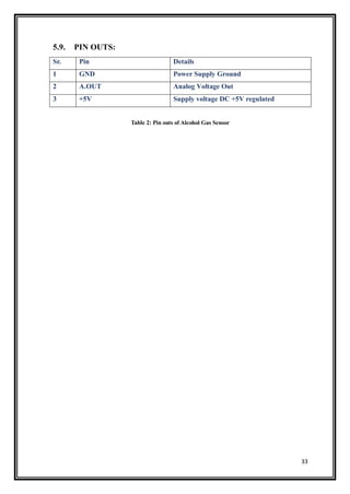
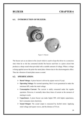
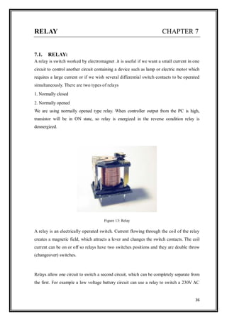
This document describes a project report submitted by two students for their bachelor's degree. It outlines the development of an alcohol detection system for vehicles using various hardware components like an alcohol sensor, microcontroller, LCD, buzzer, GSM module and motor. The system is intended to detect if a driver has consumed alcohol and prevent the vehicle from starting by activating the buzzer and taking control of the vehicle remotely through wireless communication.