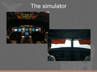
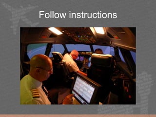
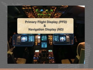
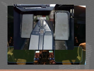
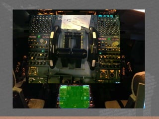
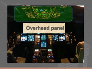
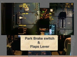
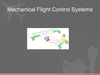
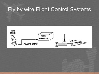
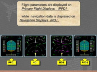
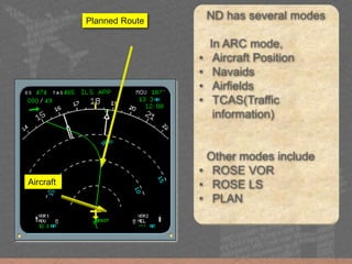
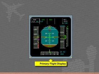
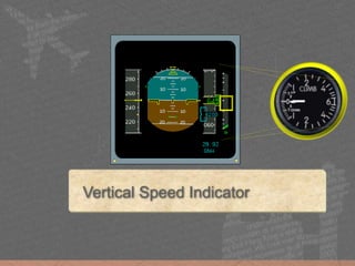
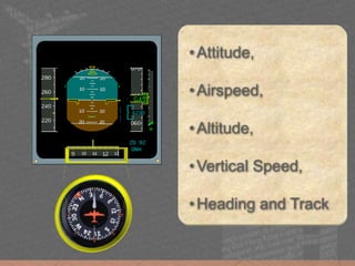
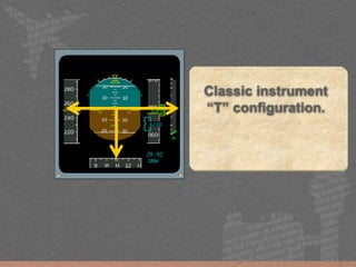
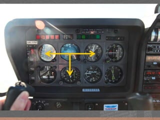
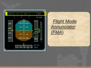
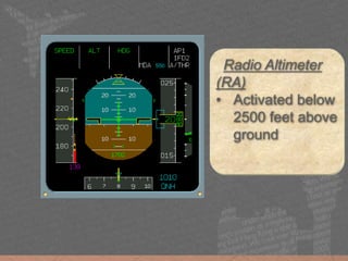
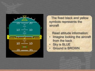
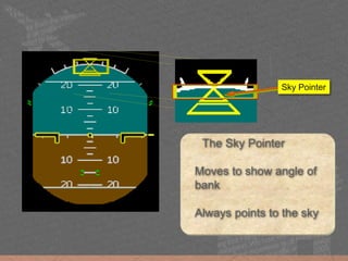
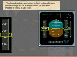
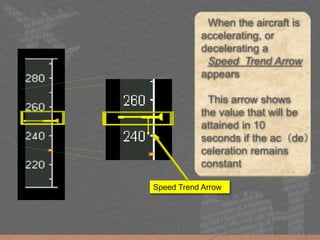
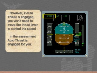
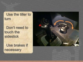
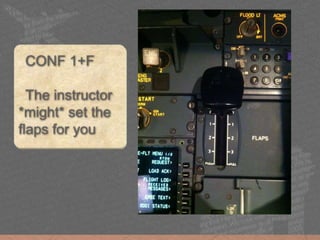
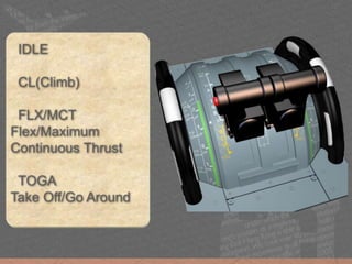
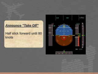
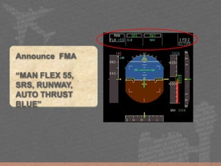
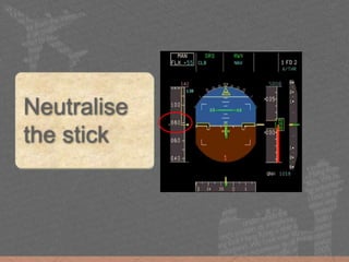
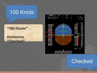
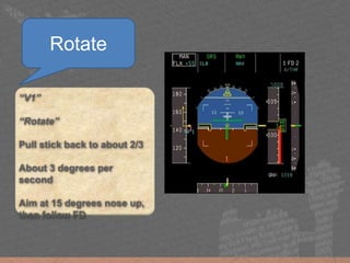
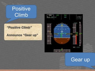
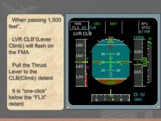
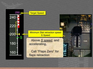
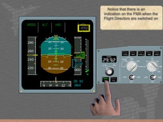
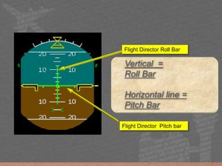
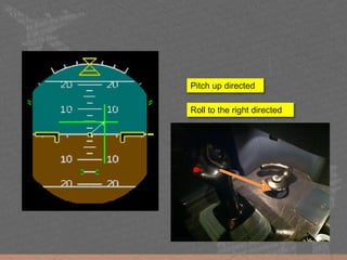
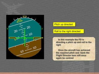
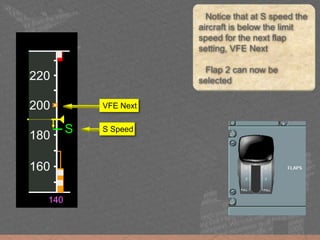
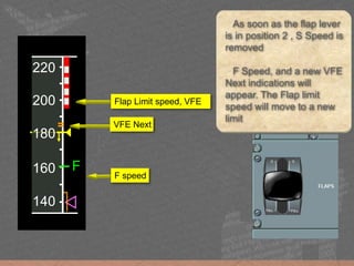
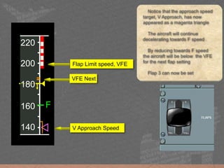
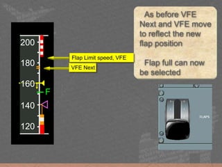
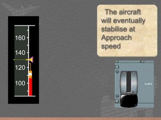
Recap on Airbus A330 sim practice
The final preparation before DACP screening
Yuuji Izumo Jacklyn Wu
CARE - Charity for Aviation - Recreation and Education
The assessment will be held in Cathay
City
You will fly a level D A330 Simulator
The simulator
Follow instructions
Primary Flight Display (PFD)
&
Navigation Display (ND)
Sidestick &
Steering Hand Wheels (Tiller)
Rudder & Brake pedal
Overhead panel
Park Brake switch
&
Flaps Lever
Mechanical Flight Control Systems
Fly by wire Flight Control Systems
Primary Flight Display (PFD)
&
Navigation Display (ND)
Flight parameters are displayed on
Primary Flight Displays (PFD)
while navigation data is displayed on
Navigation Displays(ND)
PFD1 PFD2ND1 ND2
ND has several modes
In ARC mode,
• Aircraft Position
• Navaids
• Airfields
• TCAS(Traffic
information)
Other modes include
• ROSE VOR
• ROSE LS
• PLAN
Planned Route
Aircraft
Primary Flight Display
Artificial Horizon
Indicated Air Speed
Altimeter
Vertical Speed Indicator
•Attitude,
•Airspeed,
•Altitude,
•Vertical Speed,
•Heading and Track
Classic instrument
“T” configuration.
Flight Mode
Annunciator
(FMA)
Radio Altimeter
(RA)
• Activated below
2500 feet above
ground
The fixed black and yellow
symbols represents the
aircraft
Read attitude information:
• Imagine looking the aircraft
from the back
• Sky is BLUE
• Ground is BROWN
The Sky Pointer
Moves to show angle of
bank
Always points to the sky
Sky Pointer
Indicates side slip
Replaces the balance
indicator(the ball)
Side Slip
Index
30 degrees
20 degrees
10 degrees
The fixed black and yellow
symbols represents the
aircraft
The fixed black and yellow
symbols represents the
aircraft
The gray compass scale
moves against a fixed
yellow line which
represents the centerline of
the aircraft
In the example shown the
aircraft is heading 091
degrees
HEADING 091
TRACK DIAMOND
Small green diamond
represents the aircraft track
In the example shown the
track is 094 degrees which
means that the aircraft has 3
degrees of drift to the right
TRACK 094
The main part of the
display is dedicated to the
Altimeter. To the far right
is the Vertical Speed
display
Altimeter Vertical Speed
STD
FL 70
In the final stage of
an approach the
ground reference
ribbon will reappear
along with a landing
elevation line
30.08
QNH
Ground Reference Ribbon
Landing Elevation Line
The Speed scale moves behind a fixed yellow reference
line and triangle. In the example shown the indicated
airspeed is steady at 250 knots
When the aircraft is
accelerating, or
decelerating a
Speed Trend Arrow
appears
This arrow shows
the value that will be
attained in 10
seconds if the ac(de)
celeration remains
constant
Speed Trend Arrow
However, if Auto
Thrust is engaged,
you won’t need to
move the thrust lever
to control the speed
In the assessment
Auto Thrust is
engaged for you.
Use the tiller to
turn
Don’t need to
touch the
sidestick
Use brakes if
necessary
CONF 1+F
The instructor
*might* set the
flaps for you
IDLE
CL(Climb)
FLX/MCT
Flex/Maximum
Continuous Thrust
TOGA
Take Off/Go Around
Announce “Take Off”
Half stick forward until 80
knots
Announce FMA
“MAN FLEX 55,
SRS, RUNWAY,
AUTO THRUST
BLUE”
Neutralise
the stick
“100 Knots”
Announce
“Checked”
100 Knots
Checked
“V1”
“Rotate”
Pull stick back to about 2/3
About 3 degrees per
second
Aim at 15 degrees nose up,
then follow FD
Rotate
“Positive Climb”
Announce “Gear up”
Positive
Climb
Gear up
LVR CLB
When passing 1,500
feet“,
LVR CLB”(Lever
Climb) will flash on
the FMA
Pull the Thrust
Lever to the
CLB(Climb) detent
It is “one-click”
below the “FLX”
detent
160
180
200
250
220
S
240
Above S speed, and
accelerating,
Call “Flaps Zero” for
flaps retraction
Target Speed
Minimum Slat retraction speed
S Speed
THE MOST IMPORTANT
PART
You have control.
I have control.
Each side stick is fitted
with a red “take-over
pushbutton”
Autopilot is disconnected
if the button is pressed
Press twice to cancel
audible warning
If both sidesticks are being
moved at the same time, the pilot
flying can keep pressing the Take-
over pushbutton to gain control
The arrow points left showing
that the Captain has control
Avoid moving the sidestick when
another pilot is having control
When the Flight Director
is selected
Flight Director
indications are on the
attitude indicator
Notice that there is an
indication on the FMA when the
Flight Directors are switched on
Vertical =
Roll Bar
Horizontal line =
Pitch Bar
Flight Director Roll Bar
Flight Director Pitch bar
Roll to the right directed
Pitch up directed
In this example the FD is
directing a pitch up and roll to the
right
Once the aircraft has achieved
the required pitch and bank the
Flight Director bars will once
again be centred
Roll to the right directed
Pitch up directed
Approach and Landing
Localiser indicator
indicates the aircraft’s
horizontal position
relative to the
centreline of the
runway
Glideslope indicator
indicates the aircraft’s
vertical position
relative to a 3 degrees
profile to the runway
220
240
260
280
=
o
180
200
220
240
=
o
140
When the aircraft decelerates
to Green Dot Speed and below
VFE next, Flap 1 can now be
selected.
Note that a target speed of
140 knots has appeared. This
represents the approach speed
targetVFE Next
180
200
220
240
=
o
140
160
180
200
220
=
S
140
Once the flap lever is
in position 1, S Speed,
VFE Next and the Flap
limit speed indications
will appear
The speed will
decrease towards S
speed
VFE Next
Flap Limit speed, VFE
S Speed
160
180
200
220
=
S
140
Notice that at S speed the
aircraft is below the limit
speed for the next flap
setting, VFE Next
Flap 2 can now be
selected
VFE Next
S Speed
160
180
200
220
=
S
140
160
180
200
220
=
F
140
As soon as the flap lever
is in position 2 , S Speed is
removed
F Speed, and a new VFE
Next indications will
appear. The Flap limit
speed will move to a new
limit
VFE Next
Flap Limit speed, VFE
F speed
160
180
200
220
=
F
140
Notice that the approach speed
target, V Approach, has now
appeared as a magenta triangle
The aircraft will continue
decelerating towards F speed
By reducing towards F speed
the aircraft will be below the VFE
for the next flap setting
Flap 3 can now be set
VFE Next
Flap Limit speed, VFE
V Approach Speed
160
180
200
220
=
F
140
140
160
180
200
=
F
120
As before VFE
Next and VFE move
to reflect the new
flap position
Flap full can now
be selected
VFE Next
Flap Limit speed, VFE
140
160
180
200
=
F
120
100
120
140
160
The aircraft
will eventually
stabilise at
Approach
speed
The most important part :
FOLLOW the FD
Enjoy the flight
Seat Adjustment
Forward/Backward
Upward/Downward
Seat Adjustment
Height
Pitch
Pedal Adjustment
slideshare.com/careaviaiton.hk

Recap on Airbus A330 sim practice