SlideShare a Scribd company logo
1 of 32
Download to read offline
1
3D Bearing Support
Estimated time required: ~30 min
Experience level: Lower
MD Patran/Nastran
2
Topics Covered
• Creating 3D geometry using primitive solids in Patran
• Using Boolean geometry to merge and subtract geometries from part
• Transforming solid geometry by mirroring using 3 points along a plane
• Using Tetmesher with Tet10 elements for meshing solid geometry
•Applying uniform pressure load to a surface
3
Problem Description
The structure shown below is designed to support a bearing on its right
(curved) surface. For this example, the left end is cantilevered. This means
that both the translational and the rotational are held to zero along this
surface. A pressure of 100 psi is applied normal to the surface curvature
where the bearing resides.
10 in
0.25 in
6 in
5 in
4 in
Radius 1.0 in
Radius 2.75 in
Modulus of Elasticity = 10e6 psi
Poisson’s ratio = 0.3
Thickness = 3 in
4
Goal
• Use the 3D geometric modeling kernel of Patran to build the model
•Mesh the solid geometry using Tetmesh using Tet10 topology
• Determine the von Mises stress of the model of the bearing support
• Determine the displacement of the model of the bearing support
5
Expected Results
von Mises Stress Displacement
Maximum stress = 1.65e3 psi @ Nd 3025
Minimum stress = 2.85e1 psi @ Nd 276
Maximum displacement = 1.83e-3 in. @ Nd 6
Minimum displacement = 0 in. @ Nd 1598
6
Animation
7
Starting MSC.Patran from Windows
a. Click on start menu
b. Roll mouse over All Programs
c. Roll mouse over MSC.Software
d. Roll mouse over MSC.Patran
2005 r2
e. Click on MSC.Patran 2005 r2
To start MSC.Patran from a
windows computer you will have to:
8
Creating a New Database
a
a. Click File menu / Select New.
b. In the File name text field enter
bearing_support
c. Click OK button
d. Under Tolerance select Default.
e. For Analysis Code select MSC.Nastran
from the drop down menu
f. For Analysis Type select Structural from
the drop down menu
g. Click OK button
Note: MSC.Patran defaults the working folder to C:/windows/temp. Make sure the folder content is
deleted or backed up before starting a new database to avoid confusing among files.
b c
e
f
g
d
9
a
Creating Solid Geometry with Block Primitive
a. Click on Geometry icon
b. Select Create / Solid /
Primitive from the drop
down menus
c. Click on the Block icon
d. In the X Length List text
field enter 10
e. In the Y Length List text
field enter 2
f. In the Z Length List text
field enter 3
g. Click on Auto Execute box
to turn it Off
h. In the Base Origin Point
List text field enter [0, 0, 0]
i. Click Apply button
j. Click on the Iso 1 View icon
k. Click on Hidden Line icon
b
c
d
e
f
g
h
i
j
k
10
Creating Additional Solid Geometry with Block Primitive
a. Select Create / Solid /
Primitive from the drop
down menu
b. Click on Block icon
c. In X Length List text field
enter 1
d. In Y Length List text field
enter 3
e. In Z Length List text field
enter 3
f. Click on Auto Execute
check box to turn it Off
g. In Base Origin Point List
text field enter [10, -1, 0].
Note that the y coordinate
is negative because it
starts off below the origin.
h. Click Apply button
a
b
c
e
f
g
h
d
11
Creating Additional Solid Geometry with Block Primitive
a. Select Create / Solid /
Primitive from the drop
down menu
b. Click on Block icon
c. In X Length List text field
enter 1
d. In Y Length List text field
enter 3
e. In Z Length List text field
enter 3
f. Click on Auto Execute
check box to turn it Off
g. In Base Origin Point List
text field enter [10, -1, 0].
h. Click Apply button
a
b
c
e
f
g
h
d
12
Creating Solid Geometry with Cylinder Primitive
a. Select Create / Solid /
Primitive from the drop
down menus
b. Click on Cylinder icon
c. In the Height List text field
enter -3. This is because we
are selecting the orange
point as illustrated in the
viewport. Thus the negative
sign identifies that we are
going to extrude in the
negative z direction
d. For Radius List text field
enter 1
e. In the Thickness List text
field enter 1
f. Click on Auto Execute
check box to turn it Off.
g. For the Base Center Point
List select the orange
corner illustrated on the
viewport (point 10)
h. Click Apply button
a
b
c
d
e
f
g
h
13
Creating Additional Solid Geometry with Cylinder Primitive
a. Select Create / Solid /
Primitive from the drop
down menus
b. Click on Cylinder icon
c. In the Height List text field
enter -3. This is because we
are selecting the orange
point as illustrated in the
viewport. Thus the negative
sign identifies that we are
going to extrude in the
negative z direction
d. For Radius List text field
enter 2.75
e. In the Thickness List text
field enter 2.75
f. Click on Auto Execute
check box to turn it Off.
g. For the Base Center Point
List select the orange
corner illustrated on the
viewport (point 19)
h. Click Apply button
h
g
e
d
b
a
c
f
14
Using Boolean Subtraction of Solids
a. Select Edit / Solid /
Boolean form the drop
down menu
b. Click on the Subtract Icon
c. Click on Auto Execute
check box to turn it Off
d. For Target Solid click on
the small rectangle
illustrated on the viewport
(Solid 2)
e. For the Subtracting Solid
List text field click on the
small circle illustrated on
the viewport (solid 4)
f. Click Apply button
a
b
d
c
e
f
15
Using Boolean Subtraction of Solids
a. Select Edit / Solid /
Boolean form the drop
down menu
b. Click on the Subtract Icon
c. Click on Auto Execute
check box to turn it Off
d. For Target Solid click on
the large rectangle
illustrated on the viewport
(solid 3)
e. For the Subtracting Solid
List text field click on the
large circle illustrated on
the viewport (solid 5)
f. Click Apply button
a
b
d
c
e
f
16
Using Boolean Addition of Solids
Note from the previous slide that there are three solids parts. With this step we are
going to add all three solids to make only one solid geometry
a. Select Edit / Solid / Boolean
from the drop down menus
b. Click on the Add icon
c. In the Solid List text field
select all three solids by click
and dragging a rectangular
box over all three solids.
d. Click Apply button
This step is conducted before mirroring to decrease the total number of steps. If you were to not do this
first, you will have to mirror each solid individually and then adding all the solids together.
a
b
c
d
17
Mirroring the Solid Geometry
a. Select Transforms / Solid /
Mirror from the drop down
menu
b. Click on the Define Mirror
Plane Normal text field with
out entering anything.
c. In the Picking Filter toolbar click
on 3 Point for the Plane
d. Click on the three corner
orange points as illustrated on
the viewport. Note nothing will
appear in the Desired Mirror
Plane Normal text field until all
three points are clicked
e. Click on Auto Execute check
box to turn Off
f. In the Solid List text field
select the entire solid at the
bottom
g. Click Apply button
h. The resulting view of the
viewport. Might need to refresh
and redraw the part.
a
b
c
d
e
f
g
h
18
Using Boolean Addition of Solids
a. Select Edit / Solid /
Boolean from the drop
down menus
b. Click on Add icon
c. In the Solid List text field
select both solids by
dragging a square over
them.
d. Click Apply button
a
c
b
d
19
Creating the Mesh using Tet Mesher
a. Click on Elements icon
b. Select Create / Mesh /
Solid from the drop down
menu
c. Under Element Shape
select Tet
d. Under Mesher select
TetMesh
e. Under Topology select
Tet10
f. In the Input List text field
select the entire geometry
(Solid 1)
g. For the Global Edge
Length Value text field
enter 0.5
h. Click Apply button
a
c
b
d
e
f
g
h
Note: Equivalencing the nodes is not required since there was a
single solid object and therefore no sharing of nodes
between objects
20
Creating Boundary Condition for Left-End (Cantilevered)
a
a. Click on Load/BCs icon
b. Select Create / Displacement / Nodal from the
drop down menus
c. For the New Set Name text field enter left_end
d. Click on Input Data button
e. Under Translational text field enter <0, 0, 0>
f. Under Rotational text field enter <0, 0, 0>
g. Click Ok button
h. Click Select Application Region button
i. Make sure the radio button for Geometry Filter is
on Geometry
j. Click on the text field of Select Geometry
Entities
k. From the Picking Filter toolbar click on Surface
or Face
l. Click on Iso 2 View and select the left end.
m. Click Add button
n. Click Ok button
o. Click Apply button
Note:Recall from the notation that Solid 1.8 means that it is
from solid 1 and surface 8
b
c
d
e
f
g
h
i
j
k
l
m
n
o
21
Creating Boundary Condition for Pressure Due to Bearing
a. Select Create / Pressure / Element Uniform
from the drop down menus
b. For the New Set Name text field enter
bearing_pressure
c. In the Target Element Type drop down menu
select 3D
d. Click on Input Data button
e. Under Pressure text field enter 100
f. Click Ok button
g. Click Select Application Region button
h. Make sure the radio button for Geometry Filter is
on Geometry
i. Click on the text field of Select Solid Faces
j. From the Picking Filter toolbar click on Surface
or Face
k. Select the right end curved part of the fixture
(solid 1.5)
l. Click Add button
m. Click Ok button
n. Click Apply button
a
b
c
d
e
f
g
h
i
j
k
l
m
n
22
Summery of Boundary Conditions
a. The left cantilevered en
should be constrained in
the 123456 directions as
illustrated in the viewport
b. The pressure load should
be 100 as illustrated in the
viewport a
b
23
Creating Material Properties
a. Click on Materials icon
b. Select Create / Isotropic / Manual Input
from the drop down menus
c. In the Material Name text field enter
aluminum
d. Click on Input Properties button
e. From the Constitutive Model drop down
menu select Linear Elastic
f. In the Elastic Modulus text field enter 10e6
g. In the Poisson Ratio text field enter 0.3
h. Click on Ok button
i. Click on Apply button
b
c
d
e
f
g
h
a
i
24
Applying Properties to the Solid
a
a. Click on Properties icon
b. Select Create / 3D / Solid from the
drop down menus
c. In the Property Set Name text field
enter bearing_clamp
d. Click on Input Properties button
e. Click on Mat. Prop. Name icon
f. Click on aluminum
g. Click Ok button
h. In the Select Member text field
select the part (solid 1)
i. Click Add button
j. Click Apply button
b
c
d
e
f
h
i
j
25
Analyzing Bearing Support Model
a. Click on Analysis icon
b. Select Analysis / Entire Model / Full Run from the
drop down menu
c. Click on Solution Type button
d. Make sure Linear Static radio button is selected
e. Click Ok button
f. Click Apply button
a
b
c
d
e
f
26
Loading Results
a
a. Select Access Results / Attach XDB
/ Result Entities from the drop down
menu
b. Click on Select Result File… button
c. Select bearing_support.xdb
d. Click Ok button
e. Click Apply button
b
c
d
e
27
a
Loading Results
a. Click on Results icon
b. Select Create / Quick Plot from the
drop down menu
c. Select Default, A1: Static Subcase
d. Select Stress Tensor
e. In the Quantity drop down menu
select von Mises
f. Select Constraint Forces,
translational
g. Click Apply button
b
c
d
e
f
g
Note: The fringe plot will have uneven colors like if it was not displaying well. This is to be expected; the
next slide will show you how to correct it…
28
Fixing Display of Viewport to Properly Display Fringe Plot
a. Click on Display menu and
Plot/Erase… from the main program
menus
b. Under Geometry click on the Erase
button
c. Click Ok button
29
Summary of Results
von Mises Stress Displacement
Maximum stress = 1.65e3 psi @ Nd 3025
Minimum stress = 2.85e1 psi @ Nd 276
Maximum displacement = 1.83e-3 in. @ Nd 6
Minimum displacement = 0 in. @ Nd 1598
30
Important Skills Acquired
• Creating 3D geometry using primitives in Patran (block and cylinder)
• Using Boolean geometry to merge and subtract geometries from part
• Transforming solid geometry by mirroring using 3 points on a plane
• Using Tetmesher with Tet10 elements for meshing solid geometry
•Applying uniform pressure load to a given surface
31
Further Analysis (Optional)
• It can be clearly observed from the results that the stress will concentrate in the
edges furthest to the right where the bearing comes into contact with the
support. What will be a good method to reduce such stresses (use FEA analysis
to prove predictions)
32
Best Practices
• When modeling a part that has symmetry along a plane,
take advantage of such characteristic to save time on
having to model unnecessary parts. Translating such
geometries will be much faster
•Using Boolean relations on primitive solid geometries is
easier and faster for simple parts than to drawing the
shape of the part and then extruding.

More Related Content

Similar to Finite Element Analysis of 3D Bearing Support.ppt

Zmorph Dual Head User Manual for Printing
Zmorph Dual Head User Manual for PrintingZmorph Dual Head User Manual for Printing
Zmorph Dual Head User Manual for PrintingRyan Dunn
 
Workshop3 pump-geo
Workshop3 pump-geoWorkshop3 pump-geo
Workshop3 pump-geommd110
 
Sheet1Wear-Ever ShoesCurrent StockProduct IDProductColorSizeQuanti.docx
Sheet1Wear-Ever ShoesCurrent StockProduct IDProductColorSizeQuanti.docxSheet1Wear-Ever ShoesCurrent StockProduct IDProductColorSizeQuanti.docx
Sheet1Wear-Ever ShoesCurrent StockProduct IDProductColorSizeQuanti.docxmaoanderton
 
Modeling seismic analysis_and_design_of_rc_building_10_story
Modeling seismic analysis_and_design_of_rc_building_10_storyModeling seismic analysis_and_design_of_rc_building_10_story
Modeling seismic analysis_and_design_of_rc_building_10_storyAliAlmayalee
 
Civil 3d Workflow_NOLOGO
Civil 3d Workflow_NOLOGOCivil 3d Workflow_NOLOGO
Civil 3d Workflow_NOLOGOGary Cassidy
 
Workshop15 rolling-plate
Workshop15 rolling-plateWorkshop15 rolling-plate
Workshop15 rolling-platemmd110
 
Workshop9 pump-mesh
Workshop9 pump-meshWorkshop9 pump-mesh
Workshop9 pump-meshmmd110
 
Workshop1 cant-beam
Workshop1 cant-beamWorkshop1 cant-beam
Workshop1 cant-beammmd110
 
Workshop9 pump-mesh2005
Workshop9 pump-mesh2005Workshop9 pump-mesh2005
Workshop9 pump-mesh2005mmd110
 
TableTitleFirst NameLast NameStreetCityStateZipNumAttendingMr.Cind.docx
TableTitleFirst NameLast NameStreetCityStateZipNumAttendingMr.Cind.docxTableTitleFirst NameLast NameStreetCityStateZipNumAttendingMr.Cind.docx
TableTitleFirst NameLast NameStreetCityStateZipNumAttendingMr.Cind.docxmattinsonjanel
 
Revenue by DepartmentBlue Lake SportsFirst Quarter Sales by CityDe.docx
Revenue by DepartmentBlue Lake SportsFirst Quarter Sales by CityDe.docxRevenue by DepartmentBlue Lake SportsFirst Quarter Sales by CityDe.docx
Revenue by DepartmentBlue Lake SportsFirst Quarter Sales by CityDe.docxronak56
 
SAP2000 Cold-formed steel truss.pdf
SAP2000 Cold-formed steel truss.pdfSAP2000 Cold-formed steel truss.pdf
SAP2000 Cold-formed steel truss.pdfstnOnurBaktr
 
Workshop10 creep-jop
Workshop10 creep-jopWorkshop10 creep-jop
Workshop10 creep-jopmmd110
 
Scrap Shedding - DynaForm_Tutorial II.pdf
Scrap Shedding - DynaForm_Tutorial II.pdfScrap Shedding - DynaForm_Tutorial II.pdf
Scrap Shedding - DynaForm_Tutorial II.pdfkeansheng
 
Sheet metal design in Solid Edge.docx
Sheet metal design in Solid Edge.docxSheet metal design in Solid Edge.docx
Sheet metal design in Solid Edge.docxSomashekar S.M
 

Similar to Finite Element Analysis of 3D Bearing Support.ppt (20)

Zmorph Dual Head User Manual for Printing
Zmorph Dual Head User Manual for PrintingZmorph Dual Head User Manual for Printing
Zmorph Dual Head User Manual for Printing
 
Workshop3 pump-geo
Workshop3 pump-geoWorkshop3 pump-geo
Workshop3 pump-geo
 
Sheet1Wear-Ever ShoesCurrent StockProduct IDProductColorSizeQuanti.docx
Sheet1Wear-Ever ShoesCurrent StockProduct IDProductColorSizeQuanti.docxSheet1Wear-Ever ShoesCurrent StockProduct IDProductColorSizeQuanti.docx
Sheet1Wear-Ever ShoesCurrent StockProduct IDProductColorSizeQuanti.docx
 
Microsoft excel part 2
Microsoft excel part 2Microsoft excel part 2
Microsoft excel part 2
 
Ansys iges tutorial
Ansys iges tutorialAnsys iges tutorial
Ansys iges tutorial
 
Modeling seismic analysis_and_design_of_rc_building_10_story
Modeling seismic analysis_and_design_of_rc_building_10_storyModeling seismic analysis_and_design_of_rc_building_10_story
Modeling seismic analysis_and_design_of_rc_building_10_story
 
Civil 3d workflow
Civil 3d workflowCivil 3d workflow
Civil 3d workflow
 
Civil 3d Workflow_NOLOGO
Civil 3d Workflow_NOLOGOCivil 3d Workflow_NOLOGO
Civil 3d Workflow_NOLOGO
 
Workshop15 rolling-plate
Workshop15 rolling-plateWorkshop15 rolling-plate
Workshop15 rolling-plate
 
Workshop9 pump-mesh
Workshop9 pump-meshWorkshop9 pump-mesh
Workshop9 pump-mesh
 
Workshop1 cant-beam
Workshop1 cant-beamWorkshop1 cant-beam
Workshop1 cant-beam
 
FEMAP TUTORIAL AE410
FEMAP TUTORIAL AE410FEMAP TUTORIAL AE410
FEMAP TUTORIAL AE410
 
Workshop9 pump-mesh2005
Workshop9 pump-mesh2005Workshop9 pump-mesh2005
Workshop9 pump-mesh2005
 
TableTitleFirst NameLast NameStreetCityStateZipNumAttendingMr.Cind.docx
TableTitleFirst NameLast NameStreetCityStateZipNumAttendingMr.Cind.docxTableTitleFirst NameLast NameStreetCityStateZipNumAttendingMr.Cind.docx
TableTitleFirst NameLast NameStreetCityStateZipNumAttendingMr.Cind.docx
 
Revenue by DepartmentBlue Lake SportsFirst Quarter Sales by CityDe.docx
Revenue by DepartmentBlue Lake SportsFirst Quarter Sales by CityDe.docxRevenue by DepartmentBlue Lake SportsFirst Quarter Sales by CityDe.docx
Revenue by DepartmentBlue Lake SportsFirst Quarter Sales by CityDe.docx
 
SAP2000 Cold-formed steel truss.pdf
SAP2000 Cold-formed steel truss.pdfSAP2000 Cold-formed steel truss.pdf
SAP2000 Cold-formed steel truss.pdf
 
Workshop10 creep-jop
Workshop10 creep-jopWorkshop10 creep-jop
Workshop10 creep-jop
 
Scrap Shedding - DynaForm_Tutorial II.pdf
Scrap Shedding - DynaForm_Tutorial II.pdfScrap Shedding - DynaForm_Tutorial II.pdf
Scrap Shedding - DynaForm_Tutorial II.pdf
 
Surface machining
Surface machiningSurface machining
Surface machining
 
Sheet metal design in Solid Edge.docx
Sheet metal design in Solid Edge.docxSheet metal design in Solid Edge.docx
Sheet metal design in Solid Edge.docx
 

More from keansheng

Implicit Statistics - IMPLSTAT v2.0 in LSPrepost.pdf
Implicit Statistics - IMPLSTAT v2.0 in LSPrepost.pdfImplicit Statistics - IMPLSTAT v2.0 in LSPrepost.pdf
Implicit Statistics - IMPLSTAT v2.0 in LSPrepost.pdfkeansheng
 
LNG Combustion with LS-Dyna CESE Solvers.pdf
LNG Combustion with LS-Dyna CESE Solvers.pdfLNG Combustion with LS-Dyna CESE Solvers.pdf
LNG Combustion with LS-Dyna CESE Solvers.pdfkeansheng
 
ICFD Tutorial - Two Dimensional Cylinder Flow.pdf
ICFD Tutorial - Two Dimensional Cylinder Flow.pdfICFD Tutorial - Two Dimensional Cylinder Flow.pdf
ICFD Tutorial - Two Dimensional Cylinder Flow.pdfkeansheng
 
ICFD Setup With New Solution Explorer.pdf
ICFD Setup With New Solution Explorer.pdfICFD Setup With New Solution Explorer.pdf
ICFD Setup With New Solution Explorer.pdfkeansheng
 
CFD Simulation using LS-Dyna ICFD Method.pdf
CFD Simulation using LS-Dyna ICFD Method.pdfCFD Simulation using LS-Dyna ICFD Method.pdf
CFD Simulation using LS-Dyna ICFD Method.pdfkeansheng
 
LS-Dyna Element Free Galerkin User's Manual.pdf
LS-Dyna Element Free Galerkin User's Manual.pdfLS-Dyna Element Free Galerkin User's Manual.pdf
LS-Dyna Element Free Galerkin User's Manual.pdfkeansheng
 
Smoothed Particle Galerkin Method Formulation.pdf
Smoothed Particle Galerkin Method Formulation.pdfSmoothed Particle Galerkin Method Formulation.pdf
Smoothed Particle Galerkin Method Formulation.pdfkeansheng
 
Advanced FEM and Meshfree Class Workshop.pdf
Advanced FEM and Meshfree Class Workshop.pdfAdvanced FEM and Meshfree Class Workshop.pdf
Advanced FEM and Meshfree Class Workshop.pdfkeansheng
 
Structural behaviour of structures in fire.pdf
Structural behaviour of structures in fire.pdfStructural behaviour of structures in fire.pdf
Structural behaviour of structures in fire.pdfkeansheng
 
Modelling of floating ship in Ls-Dyna.pdf
Modelling of floating ship in Ls-Dyna.pdfModelling of floating ship in Ls-Dyna.pdf
Modelling of floating ship in Ls-Dyna.pdfkeansheng
 
Modelling of blast mine on plate in Ls-Dyna.pdf
Modelling of blast mine on plate in Ls-Dyna.pdfModelling of blast mine on plate in Ls-Dyna.pdf
Modelling of blast mine on plate in Ls-Dyna.pdfkeansheng
 
Modelling of mine explosion using S-ALE.pdf
Modelling of mine explosion using S-ALE.pdfModelling of mine explosion using S-ALE.pdf
Modelling of mine explosion using S-ALE.pdfkeansheng
 
Modelling of projectile impacting oblique plate S-ALE.pdf
Modelling of projectile impacting oblique plate S-ALE.pdfModelling of projectile impacting oblique plate S-ALE.pdf
Modelling of projectile impacting oblique plate S-ALE.pdfkeansheng
 
water sloshing in a tank using s-ale.pptx
water sloshing in a tank using s-ale.pptxwater sloshing in a tank using s-ale.pptx
water sloshing in a tank using s-ale.pptxkeansheng
 
Sheet Metal Transferring/Handling Training Tutorial II.pdf
Sheet Metal Transferring/Handling Training Tutorial II.pdfSheet Metal Transferring/Handling Training Tutorial II.pdf
Sheet Metal Transferring/Handling Training Tutorial II.pdfkeansheng
 

More from keansheng (15)

Implicit Statistics - IMPLSTAT v2.0 in LSPrepost.pdf
Implicit Statistics - IMPLSTAT v2.0 in LSPrepost.pdfImplicit Statistics - IMPLSTAT v2.0 in LSPrepost.pdf
Implicit Statistics - IMPLSTAT v2.0 in LSPrepost.pdf
 
LNG Combustion with LS-Dyna CESE Solvers.pdf
LNG Combustion with LS-Dyna CESE Solvers.pdfLNG Combustion with LS-Dyna CESE Solvers.pdf
LNG Combustion with LS-Dyna CESE Solvers.pdf
 
ICFD Tutorial - Two Dimensional Cylinder Flow.pdf
ICFD Tutorial - Two Dimensional Cylinder Flow.pdfICFD Tutorial - Two Dimensional Cylinder Flow.pdf
ICFD Tutorial - Two Dimensional Cylinder Flow.pdf
 
ICFD Setup With New Solution Explorer.pdf
ICFD Setup With New Solution Explorer.pdfICFD Setup With New Solution Explorer.pdf
ICFD Setup With New Solution Explorer.pdf
 
CFD Simulation using LS-Dyna ICFD Method.pdf
CFD Simulation using LS-Dyna ICFD Method.pdfCFD Simulation using LS-Dyna ICFD Method.pdf
CFD Simulation using LS-Dyna ICFD Method.pdf
 
LS-Dyna Element Free Galerkin User's Manual.pdf
LS-Dyna Element Free Galerkin User's Manual.pdfLS-Dyna Element Free Galerkin User's Manual.pdf
LS-Dyna Element Free Galerkin User's Manual.pdf
 
Smoothed Particle Galerkin Method Formulation.pdf
Smoothed Particle Galerkin Method Formulation.pdfSmoothed Particle Galerkin Method Formulation.pdf
Smoothed Particle Galerkin Method Formulation.pdf
 
Advanced FEM and Meshfree Class Workshop.pdf
Advanced FEM and Meshfree Class Workshop.pdfAdvanced FEM and Meshfree Class Workshop.pdf
Advanced FEM and Meshfree Class Workshop.pdf
 
Structural behaviour of structures in fire.pdf
Structural behaviour of structures in fire.pdfStructural behaviour of structures in fire.pdf
Structural behaviour of structures in fire.pdf
 
Modelling of floating ship in Ls-Dyna.pdf
Modelling of floating ship in Ls-Dyna.pdfModelling of floating ship in Ls-Dyna.pdf
Modelling of floating ship in Ls-Dyna.pdf
 
Modelling of blast mine on plate in Ls-Dyna.pdf
Modelling of blast mine on plate in Ls-Dyna.pdfModelling of blast mine on plate in Ls-Dyna.pdf
Modelling of blast mine on plate in Ls-Dyna.pdf
 
Modelling of mine explosion using S-ALE.pdf
Modelling of mine explosion using S-ALE.pdfModelling of mine explosion using S-ALE.pdf
Modelling of mine explosion using S-ALE.pdf
 
Modelling of projectile impacting oblique plate S-ALE.pdf
Modelling of projectile impacting oblique plate S-ALE.pdfModelling of projectile impacting oblique plate S-ALE.pdf
Modelling of projectile impacting oblique plate S-ALE.pdf
 
water sloshing in a tank using s-ale.pptx
water sloshing in a tank using s-ale.pptxwater sloshing in a tank using s-ale.pptx
water sloshing in a tank using s-ale.pptx
 
Sheet Metal Transferring/Handling Training Tutorial II.pdf
Sheet Metal Transferring/Handling Training Tutorial II.pdfSheet Metal Transferring/Handling Training Tutorial II.pdf
Sheet Metal Transferring/Handling Training Tutorial II.pdf
 

Recently uploaded

Call Girls Service Nagpur Tanvi Call 7001035870 Meet With Nagpur Escorts
Call Girls Service Nagpur Tanvi Call 7001035870 Meet With Nagpur EscortsCall Girls Service Nagpur Tanvi Call 7001035870 Meet With Nagpur Escorts
Call Girls Service Nagpur Tanvi Call 7001035870 Meet With Nagpur EscortsCall Girls in Nagpur High Profile
 
High Profile Call Girls Nagpur Meera Call 7001035870 Meet With Nagpur Escorts
High Profile Call Girls Nagpur Meera Call 7001035870 Meet With Nagpur EscortsHigh Profile Call Girls Nagpur Meera Call 7001035870 Meet With Nagpur Escorts
High Profile Call Girls Nagpur Meera Call 7001035870 Meet With Nagpur EscortsCall Girls in Nagpur High Profile
 
Model Call Girl in Narela Delhi reach out to us at 🔝8264348440🔝
Model Call Girl in Narela Delhi reach out to us at 🔝8264348440🔝Model Call Girl in Narela Delhi reach out to us at 🔝8264348440🔝
Model Call Girl in Narela Delhi reach out to us at 🔝8264348440🔝soniya singh
 
Processing & Properties of Floor and Wall Tiles.pptx
Processing & Properties of Floor and Wall Tiles.pptxProcessing & Properties of Floor and Wall Tiles.pptx
Processing & Properties of Floor and Wall Tiles.pptxpranjaldaimarysona
 
Analog to Digital and Digital to Analog Converter
Analog to Digital and Digital to Analog ConverterAnalog to Digital and Digital to Analog Converter
Analog to Digital and Digital to Analog ConverterAbhinavSharma374939
 
What are the advantages and disadvantages of membrane structures.pptx
What are the advantages and disadvantages of membrane structures.pptxWhat are the advantages and disadvantages of membrane structures.pptx
What are the advantages and disadvantages of membrane structures.pptxwendy cai
 
Decoding Kotlin - Your guide to solving the mysterious in Kotlin.pptx
Decoding Kotlin - Your guide to solving the mysterious in Kotlin.pptxDecoding Kotlin - Your guide to solving the mysterious in Kotlin.pptx
Decoding Kotlin - Your guide to solving the mysterious in Kotlin.pptxJoão Esperancinha
 
(RIA) Call Girls Bhosari ( 7001035870 ) HI-Fi Pune Escorts Service
(RIA) Call Girls Bhosari ( 7001035870 ) HI-Fi Pune Escorts Service(RIA) Call Girls Bhosari ( 7001035870 ) HI-Fi Pune Escorts Service
(RIA) Call Girls Bhosari ( 7001035870 ) HI-Fi Pune Escorts Serviceranjana rawat
 
Introduction and different types of Ethernet.pptx
Introduction and different types of Ethernet.pptxIntroduction and different types of Ethernet.pptx
Introduction and different types of Ethernet.pptxupamatechverse
 
IMPLICATIONS OF THE ABOVE HOLISTIC UNDERSTANDING OF HARMONY ON PROFESSIONAL E...
IMPLICATIONS OF THE ABOVE HOLISTIC UNDERSTANDING OF HARMONY ON PROFESSIONAL E...IMPLICATIONS OF THE ABOVE HOLISTIC UNDERSTANDING OF HARMONY ON PROFESSIONAL E...
IMPLICATIONS OF THE ABOVE HOLISTIC UNDERSTANDING OF HARMONY ON PROFESSIONAL E...RajaP95
 
Introduction to IEEE STANDARDS and its different types.pptx
Introduction to IEEE STANDARDS and its different types.pptxIntroduction to IEEE STANDARDS and its different types.pptx
Introduction to IEEE STANDARDS and its different types.pptxupamatechverse
 
(PRIYA) Rajgurunagar Call Girls Just Call 7001035870 [ Cash on Delivery ] Pun...
(PRIYA) Rajgurunagar Call Girls Just Call 7001035870 [ Cash on Delivery ] Pun...(PRIYA) Rajgurunagar Call Girls Just Call 7001035870 [ Cash on Delivery ] Pun...
(PRIYA) Rajgurunagar Call Girls Just Call 7001035870 [ Cash on Delivery ] Pun...ranjana rawat
 
Software Development Life Cycle By Team Orange (Dept. of Pharmacy)
Software Development Life Cycle By  Team Orange (Dept. of Pharmacy)Software Development Life Cycle By  Team Orange (Dept. of Pharmacy)
Software Development Life Cycle By Team Orange (Dept. of Pharmacy)Suman Mia
 
Biology for Computer Engineers Course Handout.pptx
Biology for Computer Engineers Course Handout.pptxBiology for Computer Engineers Course Handout.pptx
Biology for Computer Engineers Course Handout.pptxDeepakSakkari2
 
ZXCTN 5804 / ZTE PTN / ZTE POTN / ZTE 5804 PTN / ZTE POTN 5804 ( 100/200 GE Z...
ZXCTN 5804 / ZTE PTN / ZTE POTN / ZTE 5804 PTN / ZTE POTN 5804 ( 100/200 GE Z...ZXCTN 5804 / ZTE PTN / ZTE POTN / ZTE 5804 PTN / ZTE POTN 5804 ( 100/200 GE Z...
ZXCTN 5804 / ZTE PTN / ZTE POTN / ZTE 5804 PTN / ZTE POTN 5804 ( 100/200 GE Z...ZTE
 
Call Girls in Nagpur Suman Call 7001035870 Meet With Nagpur Escorts
Call Girls in Nagpur Suman Call 7001035870 Meet With Nagpur EscortsCall Girls in Nagpur Suman Call 7001035870 Meet With Nagpur Escorts
Call Girls in Nagpur Suman Call 7001035870 Meet With Nagpur EscortsCall Girls in Nagpur High Profile
 
IVE Industry Focused Event - Defence Sector 2024
IVE Industry Focused Event - Defence Sector 2024IVE Industry Focused Event - Defence Sector 2024
IVE Industry Focused Event - Defence Sector 2024Mark Billinghurst
 
GDSC ASEB Gen AI study jams presentation
GDSC ASEB Gen AI study jams presentationGDSC ASEB Gen AI study jams presentation
GDSC ASEB Gen AI study jams presentationGDSCAESB
 
OSVC_Meta-Data based Simulation Automation to overcome Verification Challenge...
OSVC_Meta-Data based Simulation Automation to overcome Verification Challenge...OSVC_Meta-Data based Simulation Automation to overcome Verification Challenge...
OSVC_Meta-Data based Simulation Automation to overcome Verification Challenge...Soham Mondal
 
HARDNESS, FRACTURE TOUGHNESS AND STRENGTH OF CERAMICS
HARDNESS, FRACTURE TOUGHNESS AND STRENGTH OF CERAMICSHARDNESS, FRACTURE TOUGHNESS AND STRENGTH OF CERAMICS
HARDNESS, FRACTURE TOUGHNESS AND STRENGTH OF CERAMICSRajkumarAkumalla
 

Recently uploaded (20)

Call Girls Service Nagpur Tanvi Call 7001035870 Meet With Nagpur Escorts
Call Girls Service Nagpur Tanvi Call 7001035870 Meet With Nagpur EscortsCall Girls Service Nagpur Tanvi Call 7001035870 Meet With Nagpur Escorts
Call Girls Service Nagpur Tanvi Call 7001035870 Meet With Nagpur Escorts
 
High Profile Call Girls Nagpur Meera Call 7001035870 Meet With Nagpur Escorts
High Profile Call Girls Nagpur Meera Call 7001035870 Meet With Nagpur EscortsHigh Profile Call Girls Nagpur Meera Call 7001035870 Meet With Nagpur Escorts
High Profile Call Girls Nagpur Meera Call 7001035870 Meet With Nagpur Escorts
 
Model Call Girl in Narela Delhi reach out to us at 🔝8264348440🔝
Model Call Girl in Narela Delhi reach out to us at 🔝8264348440🔝Model Call Girl in Narela Delhi reach out to us at 🔝8264348440🔝
Model Call Girl in Narela Delhi reach out to us at 🔝8264348440🔝
 
Processing & Properties of Floor and Wall Tiles.pptx
Processing & Properties of Floor and Wall Tiles.pptxProcessing & Properties of Floor and Wall Tiles.pptx
Processing & Properties of Floor and Wall Tiles.pptx
 
Analog to Digital and Digital to Analog Converter
Analog to Digital and Digital to Analog ConverterAnalog to Digital and Digital to Analog Converter
Analog to Digital and Digital to Analog Converter
 
What are the advantages and disadvantages of membrane structures.pptx
What are the advantages and disadvantages of membrane structures.pptxWhat are the advantages and disadvantages of membrane structures.pptx
What are the advantages and disadvantages of membrane structures.pptx
 
Decoding Kotlin - Your guide to solving the mysterious in Kotlin.pptx
Decoding Kotlin - Your guide to solving the mysterious in Kotlin.pptxDecoding Kotlin - Your guide to solving the mysterious in Kotlin.pptx
Decoding Kotlin - Your guide to solving the mysterious in Kotlin.pptx
 
(RIA) Call Girls Bhosari ( 7001035870 ) HI-Fi Pune Escorts Service
(RIA) Call Girls Bhosari ( 7001035870 ) HI-Fi Pune Escorts Service(RIA) Call Girls Bhosari ( 7001035870 ) HI-Fi Pune Escorts Service
(RIA) Call Girls Bhosari ( 7001035870 ) HI-Fi Pune Escorts Service
 
Introduction and different types of Ethernet.pptx
Introduction and different types of Ethernet.pptxIntroduction and different types of Ethernet.pptx
Introduction and different types of Ethernet.pptx
 
IMPLICATIONS OF THE ABOVE HOLISTIC UNDERSTANDING OF HARMONY ON PROFESSIONAL E...
IMPLICATIONS OF THE ABOVE HOLISTIC UNDERSTANDING OF HARMONY ON PROFESSIONAL E...IMPLICATIONS OF THE ABOVE HOLISTIC UNDERSTANDING OF HARMONY ON PROFESSIONAL E...
IMPLICATIONS OF THE ABOVE HOLISTIC UNDERSTANDING OF HARMONY ON PROFESSIONAL E...
 
Introduction to IEEE STANDARDS and its different types.pptx
Introduction to IEEE STANDARDS and its different types.pptxIntroduction to IEEE STANDARDS and its different types.pptx
Introduction to IEEE STANDARDS and its different types.pptx
 
(PRIYA) Rajgurunagar Call Girls Just Call 7001035870 [ Cash on Delivery ] Pun...
(PRIYA) Rajgurunagar Call Girls Just Call 7001035870 [ Cash on Delivery ] Pun...(PRIYA) Rajgurunagar Call Girls Just Call 7001035870 [ Cash on Delivery ] Pun...
(PRIYA) Rajgurunagar Call Girls Just Call 7001035870 [ Cash on Delivery ] Pun...
 
Software Development Life Cycle By Team Orange (Dept. of Pharmacy)
Software Development Life Cycle By  Team Orange (Dept. of Pharmacy)Software Development Life Cycle By  Team Orange (Dept. of Pharmacy)
Software Development Life Cycle By Team Orange (Dept. of Pharmacy)
 
Biology for Computer Engineers Course Handout.pptx
Biology for Computer Engineers Course Handout.pptxBiology for Computer Engineers Course Handout.pptx
Biology for Computer Engineers Course Handout.pptx
 
ZXCTN 5804 / ZTE PTN / ZTE POTN / ZTE 5804 PTN / ZTE POTN 5804 ( 100/200 GE Z...
ZXCTN 5804 / ZTE PTN / ZTE POTN / ZTE 5804 PTN / ZTE POTN 5804 ( 100/200 GE Z...ZXCTN 5804 / ZTE PTN / ZTE POTN / ZTE 5804 PTN / ZTE POTN 5804 ( 100/200 GE Z...
ZXCTN 5804 / ZTE PTN / ZTE POTN / ZTE 5804 PTN / ZTE POTN 5804 ( 100/200 GE Z...
 
Call Girls in Nagpur Suman Call 7001035870 Meet With Nagpur Escorts
Call Girls in Nagpur Suman Call 7001035870 Meet With Nagpur EscortsCall Girls in Nagpur Suman Call 7001035870 Meet With Nagpur Escorts
Call Girls in Nagpur Suman Call 7001035870 Meet With Nagpur Escorts
 
IVE Industry Focused Event - Defence Sector 2024
IVE Industry Focused Event - Defence Sector 2024IVE Industry Focused Event - Defence Sector 2024
IVE Industry Focused Event - Defence Sector 2024
 
GDSC ASEB Gen AI study jams presentation
GDSC ASEB Gen AI study jams presentationGDSC ASEB Gen AI study jams presentation
GDSC ASEB Gen AI study jams presentation
 
OSVC_Meta-Data based Simulation Automation to overcome Verification Challenge...
OSVC_Meta-Data based Simulation Automation to overcome Verification Challenge...OSVC_Meta-Data based Simulation Automation to overcome Verification Challenge...
OSVC_Meta-Data based Simulation Automation to overcome Verification Challenge...
 
HARDNESS, FRACTURE TOUGHNESS AND STRENGTH OF CERAMICS
HARDNESS, FRACTURE TOUGHNESS AND STRENGTH OF CERAMICSHARDNESS, FRACTURE TOUGHNESS AND STRENGTH OF CERAMICS
HARDNESS, FRACTURE TOUGHNESS AND STRENGTH OF CERAMICS
 

Finite Element Analysis of 3D Bearing Support.ppt

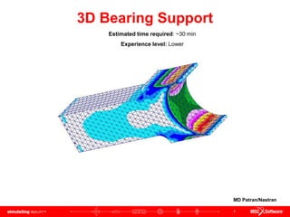
  • 1. 1 3D Bearing Support Estimated time required: ~30 min Experience level: Lower MD Patran/Nastran
  • 2. 2 Topics Covered • Creating 3D geometry using primitive solids in Patran • Using Boolean geometry to merge and subtract geometries from part • Transforming solid geometry by mirroring using 3 points along a plane • Using Tetmesher with Tet10 elements for meshing solid geometry •Applying uniform pressure load to a surface
  • 3. 3 Problem Description The structure shown below is designed to support a bearing on its right (curved) surface. For this example, the left end is cantilevered. This means that both the translational and the rotational are held to zero along this surface. A pressure of 100 psi is applied normal to the surface curvature where the bearing resides. 10 in 0.25 in 6 in 5 in 4 in Radius 1.0 in Radius 2.75 in Modulus of Elasticity = 10e6 psi Poisson’s ratio = 0.3 Thickness = 3 in
  • 4. 4 Goal • Use the 3D geometric modeling kernel of Patran to build the model •Mesh the solid geometry using Tetmesh using Tet10 topology • Determine the von Mises stress of the model of the bearing support • Determine the displacement of the model of the bearing support
  • 5. 5 Expected Results von Mises Stress Displacement Maximum stress = 1.65e3 psi @ Nd 3025 Minimum stress = 2.85e1 psi @ Nd 276 Maximum displacement = 1.83e-3 in. @ Nd 6 Minimum displacement = 0 in. @ Nd 1598
  • 7. 7 Starting MSC.Patran from Windows a. Click on start menu b. Roll mouse over All Programs c. Roll mouse over MSC.Software d. Roll mouse over MSC.Patran 2005 r2 e. Click on MSC.Patran 2005 r2 To start MSC.Patran from a windows computer you will have to:
  • 8. 8 Creating a New Database a a. Click File menu / Select New. b. In the File name text field enter bearing_support c. Click OK button d. Under Tolerance select Default. e. For Analysis Code select MSC.Nastran from the drop down menu f. For Analysis Type select Structural from the drop down menu g. Click OK button Note: MSC.Patran defaults the working folder to C:/windows/temp. Make sure the folder content is deleted or backed up before starting a new database to avoid confusing among files. b c e f g d
  • 9. 9 a Creating Solid Geometry with Block Primitive a. Click on Geometry icon b. Select Create / Solid / Primitive from the drop down menus c. Click on the Block icon d. In the X Length List text field enter 10 e. In the Y Length List text field enter 2 f. In the Z Length List text field enter 3 g. Click on Auto Execute box to turn it Off h. In the Base Origin Point List text field enter [0, 0, 0] i. Click Apply button j. Click on the Iso 1 View icon k. Click on Hidden Line icon b c d e f g h i j k
  • 10. 10 Creating Additional Solid Geometry with Block Primitive a. Select Create / Solid / Primitive from the drop down menu b. Click on Block icon c. In X Length List text field enter 1 d. In Y Length List text field enter 3 e. In Z Length List text field enter 3 f. Click on Auto Execute check box to turn it Off g. In Base Origin Point List text field enter [10, -1, 0]. Note that the y coordinate is negative because it starts off below the origin. h. Click Apply button a b c e f g h d
  • 11. 11 Creating Additional Solid Geometry with Block Primitive a. Select Create / Solid / Primitive from the drop down menu b. Click on Block icon c. In X Length List text field enter 1 d. In Y Length List text field enter 3 e. In Z Length List text field enter 3 f. Click on Auto Execute check box to turn it Off g. In Base Origin Point List text field enter [10, -1, 0]. h. Click Apply button a b c e f g h d
  • 12. 12 Creating Solid Geometry with Cylinder Primitive a. Select Create / Solid / Primitive from the drop down menus b. Click on Cylinder icon c. In the Height List text field enter -3. This is because we are selecting the orange point as illustrated in the viewport. Thus the negative sign identifies that we are going to extrude in the negative z direction d. For Radius List text field enter 1 e. In the Thickness List text field enter 1 f. Click on Auto Execute check box to turn it Off. g. For the Base Center Point List select the orange corner illustrated on the viewport (point 10) h. Click Apply button a b c d e f g h
  • 13. 13 Creating Additional Solid Geometry with Cylinder Primitive a. Select Create / Solid / Primitive from the drop down menus b. Click on Cylinder icon c. In the Height List text field enter -3. This is because we are selecting the orange point as illustrated in the viewport. Thus the negative sign identifies that we are going to extrude in the negative z direction d. For Radius List text field enter 2.75 e. In the Thickness List text field enter 2.75 f. Click on Auto Execute check box to turn it Off. g. For the Base Center Point List select the orange corner illustrated on the viewport (point 19) h. Click Apply button h g e d b a c f
  • 14. 14 Using Boolean Subtraction of Solids a. Select Edit / Solid / Boolean form the drop down menu b. Click on the Subtract Icon c. Click on Auto Execute check box to turn it Off d. For Target Solid click on the small rectangle illustrated on the viewport (Solid 2) e. For the Subtracting Solid List text field click on the small circle illustrated on the viewport (solid 4) f. Click Apply button a b d c e f
  • 15. 15 Using Boolean Subtraction of Solids a. Select Edit / Solid / Boolean form the drop down menu b. Click on the Subtract Icon c. Click on Auto Execute check box to turn it Off d. For Target Solid click on the large rectangle illustrated on the viewport (solid 3) e. For the Subtracting Solid List text field click on the large circle illustrated on the viewport (solid 5) f. Click Apply button a b d c e f
  • 16. 16 Using Boolean Addition of Solids Note from the previous slide that there are three solids parts. With this step we are going to add all three solids to make only one solid geometry a. Select Edit / Solid / Boolean from the drop down menus b. Click on the Add icon c. In the Solid List text field select all three solids by click and dragging a rectangular box over all three solids. d. Click Apply button This step is conducted before mirroring to decrease the total number of steps. If you were to not do this first, you will have to mirror each solid individually and then adding all the solids together. a b c d
  • 17. 17 Mirroring the Solid Geometry a. Select Transforms / Solid / Mirror from the drop down menu b. Click on the Define Mirror Plane Normal text field with out entering anything. c. In the Picking Filter toolbar click on 3 Point for the Plane d. Click on the three corner orange points as illustrated on the viewport. Note nothing will appear in the Desired Mirror Plane Normal text field until all three points are clicked e. Click on Auto Execute check box to turn Off f. In the Solid List text field select the entire solid at the bottom g. Click Apply button h. The resulting view of the viewport. Might need to refresh and redraw the part. a b c d e f g h
  • 18. 18 Using Boolean Addition of Solids a. Select Edit / Solid / Boolean from the drop down menus b. Click on Add icon c. In the Solid List text field select both solids by dragging a square over them. d. Click Apply button a c b d
  • 19. 19 Creating the Mesh using Tet Mesher a. Click on Elements icon b. Select Create / Mesh / Solid from the drop down menu c. Under Element Shape select Tet d. Under Mesher select TetMesh e. Under Topology select Tet10 f. In the Input List text field select the entire geometry (Solid 1) g. For the Global Edge Length Value text field enter 0.5 h. Click Apply button a c b d e f g h Note: Equivalencing the nodes is not required since there was a single solid object and therefore no sharing of nodes between objects
  • 20. 20 Creating Boundary Condition for Left-End (Cantilevered) a a. Click on Load/BCs icon b. Select Create / Displacement / Nodal from the drop down menus c. For the New Set Name text field enter left_end d. Click on Input Data button e. Under Translational text field enter <0, 0, 0> f. Under Rotational text field enter <0, 0, 0> g. Click Ok button h. Click Select Application Region button i. Make sure the radio button for Geometry Filter is on Geometry j. Click on the text field of Select Geometry Entities k. From the Picking Filter toolbar click on Surface or Face l. Click on Iso 2 View and select the left end. m. Click Add button n. Click Ok button o. Click Apply button Note:Recall from the notation that Solid 1.8 means that it is from solid 1 and surface 8 b c d e f g h i j k l m n o
  • 21. 21 Creating Boundary Condition for Pressure Due to Bearing a. Select Create / Pressure / Element Uniform from the drop down menus b. For the New Set Name text field enter bearing_pressure c. In the Target Element Type drop down menu select 3D d. Click on Input Data button e. Under Pressure text field enter 100 f. Click Ok button g. Click Select Application Region button h. Make sure the radio button for Geometry Filter is on Geometry i. Click on the text field of Select Solid Faces j. From the Picking Filter toolbar click on Surface or Face k. Select the right end curved part of the fixture (solid 1.5) l. Click Add button m. Click Ok button n. Click Apply button a b c d e f g h i j k l m n
  • 22. 22 Summery of Boundary Conditions a. The left cantilevered en should be constrained in the 123456 directions as illustrated in the viewport b. The pressure load should be 100 as illustrated in the viewport a b
  • 23. 23 Creating Material Properties a. Click on Materials icon b. Select Create / Isotropic / Manual Input from the drop down menus c. In the Material Name text field enter aluminum d. Click on Input Properties button e. From the Constitutive Model drop down menu select Linear Elastic f. In the Elastic Modulus text field enter 10e6 g. In the Poisson Ratio text field enter 0.3 h. Click on Ok button i. Click on Apply button b c d e f g h a i
  • 24. 24 Applying Properties to the Solid a a. Click on Properties icon b. Select Create / 3D / Solid from the drop down menus c. In the Property Set Name text field enter bearing_clamp d. Click on Input Properties button e. Click on Mat. Prop. Name icon f. Click on aluminum g. Click Ok button h. In the Select Member text field select the part (solid 1) i. Click Add button j. Click Apply button b c d e f h i j
  • 25. 25 Analyzing Bearing Support Model a. Click on Analysis icon b. Select Analysis / Entire Model / Full Run from the drop down menu c. Click on Solution Type button d. Make sure Linear Static radio button is selected e. Click Ok button f. Click Apply button a b c d e f
  • 26. 26 Loading Results a a. Select Access Results / Attach XDB / Result Entities from the drop down menu b. Click on Select Result File… button c. Select bearing_support.xdb d. Click Ok button e. Click Apply button b c d e
  • 27. 27 a Loading Results a. Click on Results icon b. Select Create / Quick Plot from the drop down menu c. Select Default, A1: Static Subcase d. Select Stress Tensor e. In the Quantity drop down menu select von Mises f. Select Constraint Forces, translational g. Click Apply button b c d e f g Note: The fringe plot will have uneven colors like if it was not displaying well. This is to be expected; the next slide will show you how to correct it…
  • 28. 28 Fixing Display of Viewport to Properly Display Fringe Plot a. Click on Display menu and Plot/Erase… from the main program menus b. Under Geometry click on the Erase button c. Click Ok button
  • 29. 29 Summary of Results von Mises Stress Displacement Maximum stress = 1.65e3 psi @ Nd 3025 Minimum stress = 2.85e1 psi @ Nd 276 Maximum displacement = 1.83e-3 in. @ Nd 6 Minimum displacement = 0 in. @ Nd 1598
  • 30. 30 Important Skills Acquired • Creating 3D geometry using primitives in Patran (block and cylinder) • Using Boolean geometry to merge and subtract geometries from part • Transforming solid geometry by mirroring using 3 points on a plane • Using Tetmesher with Tet10 elements for meshing solid geometry •Applying uniform pressure load to a given surface
  • 31. 31 Further Analysis (Optional) • It can be clearly observed from the results that the stress will concentrate in the edges furthest to the right where the bearing comes into contact with the support. What will be a good method to reduce such stresses (use FEA analysis to prove predictions)
  • 32. 32 Best Practices • When modeling a part that has symmetry along a plane, take advantage of such characteristic to save time on having to model unnecessary parts. Translating such geometries will be much faster •Using Boolean relations on primitive solid geometries is easier and faster for simple parts than to drawing the shape of the part and then extruding.