This document describes a model of a floating ship simulation with the following key details:
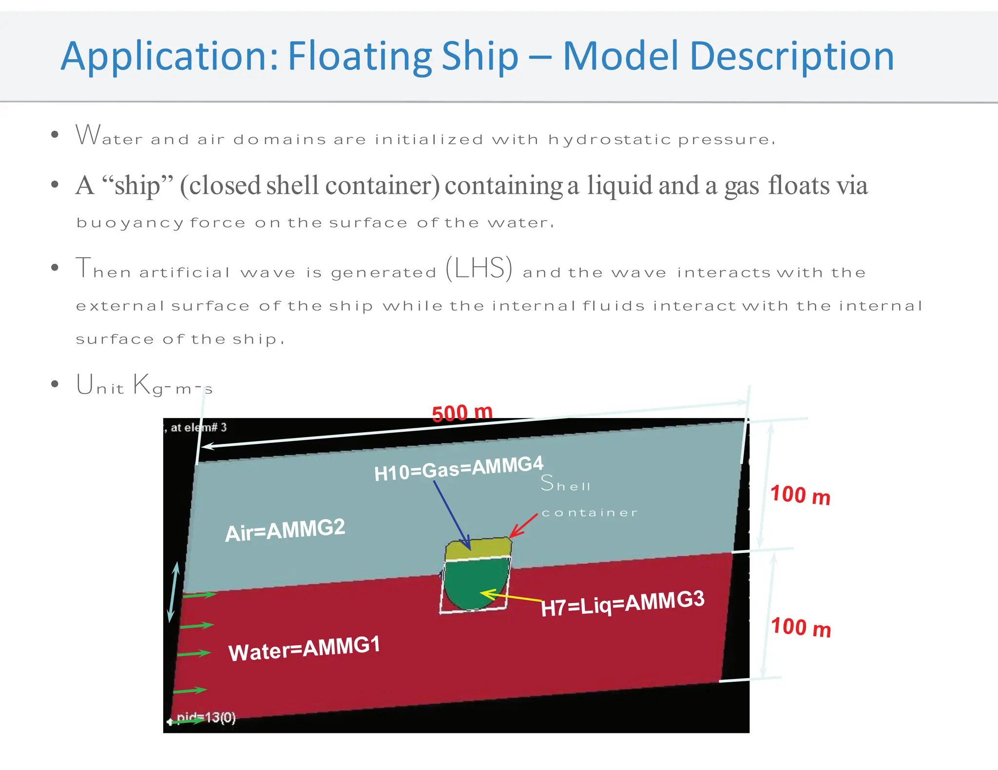
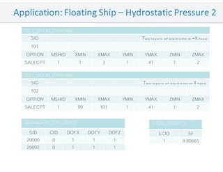
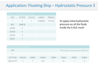
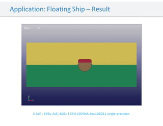
- The model initializes water and air domains with hydrostatic pressure and contains a liquid-filled shell that floats via buoyancy on the water surface.
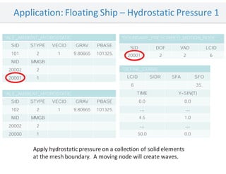
- An artificial wave is generated that interacts with the external surface of the ship while the internal fluids interact with the internal surface.
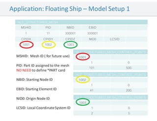
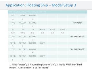
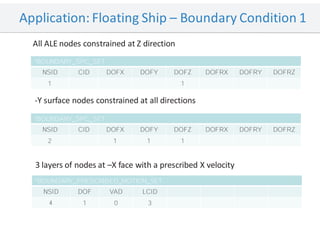
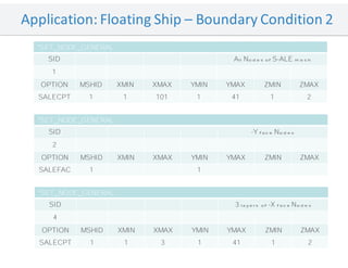
- Boundary conditions are applied including hydrostatic pressure on solid element boundaries, constraints on node movement, and a prescribed motion to generate waves on nodes at the -X face.