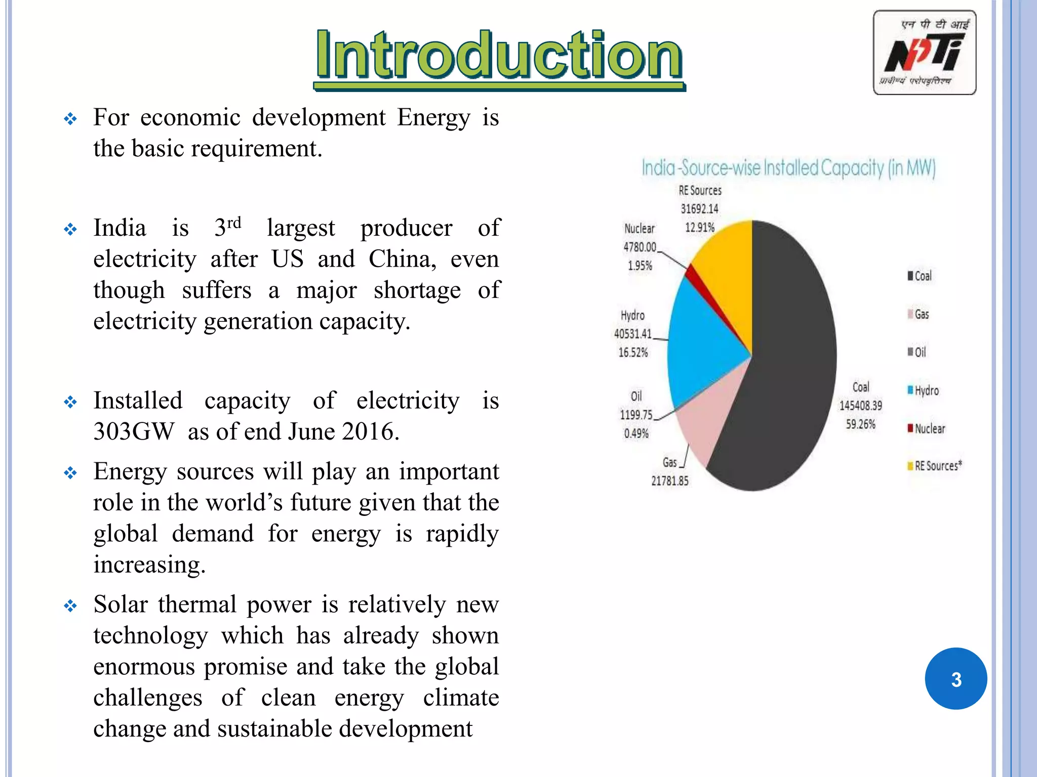
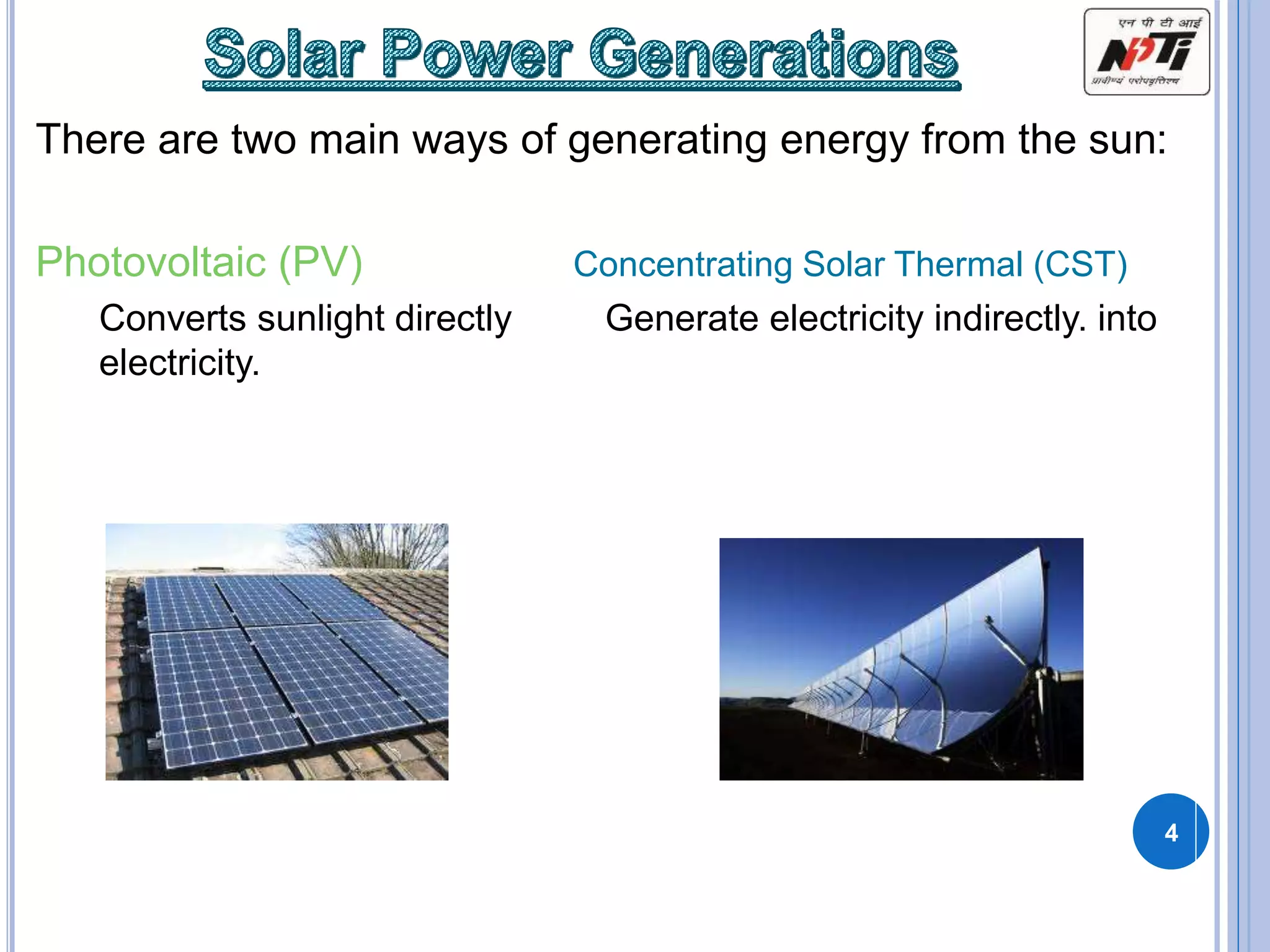
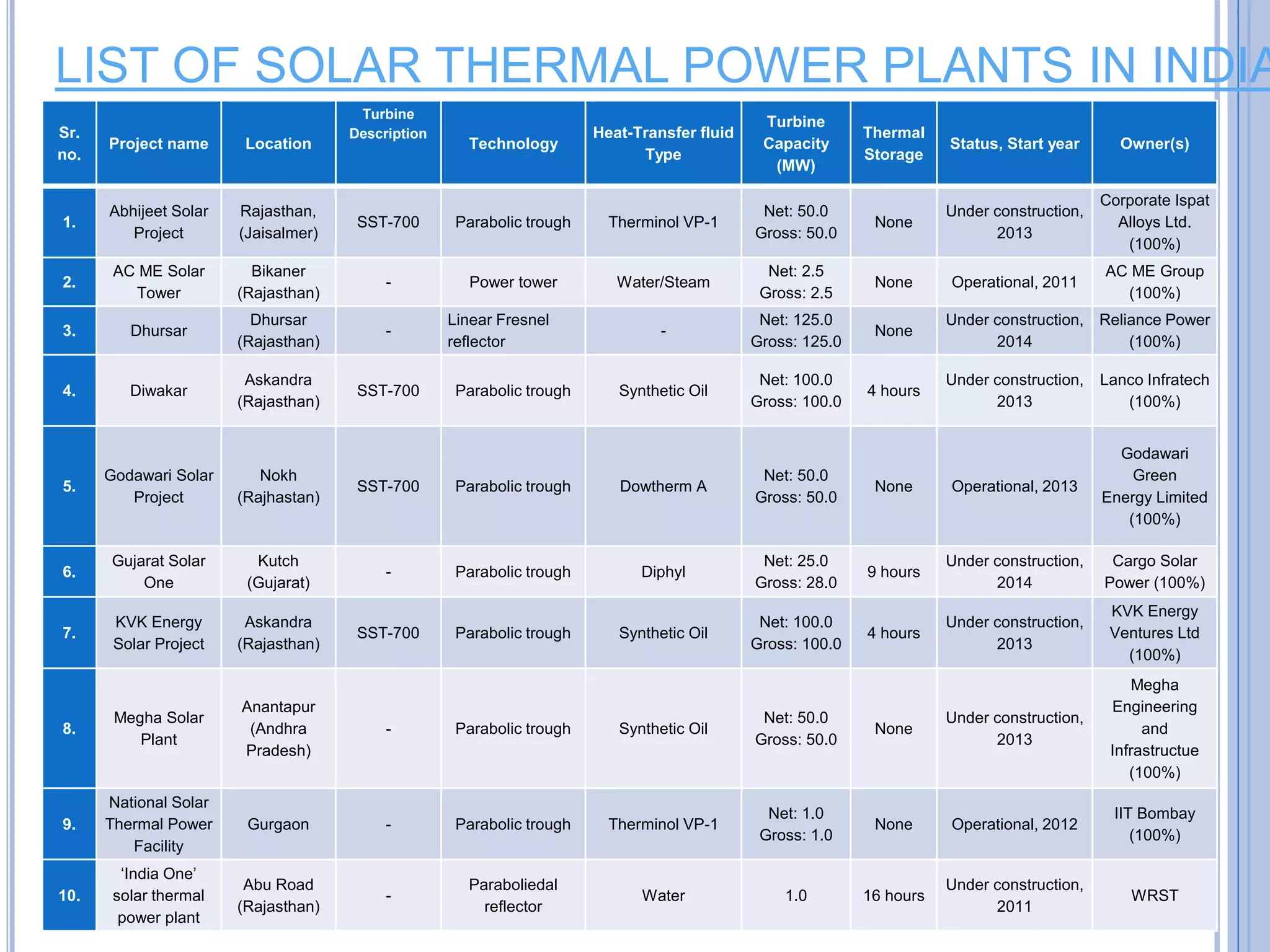
Presented By:
PRITAM PATEL
email:- pritam.patel74@gmail.com
Seminar Presentation
on
SOLAR THERMAL POWER PLANTS IN INDIA
1
OUTLINES
1. Introduction
2. Solar power generation
3. Solar thermal vs. photovoltaic
4. Basic working principle
5. Types of solar thermal power plants
6. Components of a STPP
7. CSP technologies
8. Concept of hybrid system
9. Advantages
10. Striking challenges
11. Future perspective
12. Indian scenario
13. Technological Improvement
14. conclusion 2
 For economic development Energy is
the basic requirement.
 India is 3rd largest producer of
electricity after US and China, even
though suffers a major shortage of
electricity generation capacity.
 Installed capacity of electricity is
303GW as of end June 2016.
 Energy sources will play an important
role in the world’s future given that the
global demand for energy is rapidly
increasing.
 Solar thermal power is relatively new
technology which has already shown
enormous promise and take the global
challenges of clean energy climate
change and sustainable development
3
There are two main ways of generating energy from the sun:
Photovoltaic (PV) Concentrating Solar Thermal (CST)
Converts sunlight directly Generate electricity indirectly. into
electricity.
4
5
 It is important to understand that solar thermal technology is not the same as
solar panel, or photovoltaic, technology. Solar thermal electric energy
generation concentrates the light from the sun to create heat, and that heat is
used to run a heat engine, which turns a generator to make electricity.
 The working fluid that is heated by the concentrated sunlight can be a liquid or
a gas. Different working fluids include water, oil, salts, air, nitrogen, helium,
etc. Different engine types include steam engines, gas turbines, Stirling
engines, etc. All of these engines can be quite efficient, often between 30% and
40%, and are capable of producing 10’s to 100’s of megawatts of power.
 This Stirling engine is driven by a parabolic dish that collects and concentrates
the sun into a heat source to run the engine and produce power.
 Photovoltaic, or PV energy conversion, on the other hand, directly converts the
sun’s light into electricity. This means that solar panels are only effective
during daylight hours because storing electricity is not a particularly efficient
process.
• Solar thermal power generation systems use mirrors to collect
sunlight and produce steam by solar heat to drive turbines for
generating power.
• This system generates power by rotating turbines like thermal and
nuclear power plants, and therefore, is suitable for large-scale
power generation.
6
7
 A parabolic trough consists of a linear parabolic reflector
that concentrates light onto a receiver positioned along the
reflector's focal line.
 The receiver is a tube positioned directly above the middle
of the parabolic mirror and filled with a working fluid.
 The reflector follows the sun during the daylight hours by
tracking along a single axis.
 A working fluid (e.g. molten salt) is heated to 150–350 °C
(423–623 K (302–662 °F)) as it flows through the receiver
and is then used as a heat source for a power generation
system.
8
9
10
SOLAR POWER TOWER SYSTEMS
 Power towers (also known as 'central tower' power plants or 'heliostat'
power plants).
 These designs capture and focus the sun's thermal energy with
thousands of tracking mirrors (called heliostats) in roughly a two square
mile field.
 A tower resides in the center of the heliostat field. The heliostats focus
concentrated sunlight on a receiver which sits on top of the tower.
 Within the receiver the concentrated sunlight heats molten salt to over
1,000 °F (538 °C).
 The heated molten salt then flows into a thermal storage tank where it is
stored, maintaining 98% thermal efficiency, and eventually pumped to a
steam generator.
 The steam drives a standard turbine to generate electricity.
11
12
13
14
The system consists of a stand-alone parabolic
reflector that concentrates light onto a receiver
positioned at the reflector's focal point.
The working fluid in the receiver is heated to 250–700
°C (523–973 K (482–1,292 °F)) and then used by a
Stirling engine to generate power.
Parabolic-dish systems have the highest efficiency of
all solar technologies provide solar-to-electric
efficiency between 31–32%.
Stirling Engine 
15
16
 Linear Fresnel reflectors use long, thin
segments of mirrors to focus sunlight onto a
fixed absorber located at a common focal point
of the reflectors.
 These mirrors are capable of concentrating the
sun’s energy to approximately 30 times its
normal intensity.
 This concentrated energy is transferred through
the absorber into some thermal fluid.
 The fluid then goes through a heat exchanger to
power a steam generator.
17
18
COMPONENTS OF STPP
19
20
Concentrating Solar
Technologies
Low Temperature
(<100°C)
Flat Plate
Collectors
Solar Chimney
Solar Pond
High Temperature-
Point Focusing
(>400°C)
Central Tower
Parabolic Dish
Medium Temperature – Line
Focusing (≈ 400°C)
Parabolic
Trough
Fresnel
Collectors
Commercial CSP
Parabolic
Trough
Central
Tower
Dish Stirling Fresnel
Collector
• Temp~400°C
• Line Focusing
• Linear Receiver tube
• Water consuming
• Conc.: Parabolic Mirrors
• Heat Storage feasible
• Most Commercialized
• Good for Hybrid option
• Requires flat land
• Good receiver η but low turbine η
21
Commercial CSP
Parabolic
Trough
Central
Tower
Dish Stirling Fresnel
Collector
• Temp~600-800°C
• Point Focusing
• Flat Conc. Mirrors
• Commercially proven
• Central Receiver
• Water consuming
• Heat Storage capability
• Feasible on Non Flat sites
• Good performance for large
capacity & temperatures
• Low receiver η but good turbine η
22
Commercial CSP
Parabolic
Trough
Central Tower Dish Stirling Fresnel
Collector
23
• Temp~700-800°C
• Point Focusing
• Uses Dish concentrator
• Stirling Engine
• Generally 25 kW units
• High Efficiency ~ 30%
• Dry cooling
• No water requirement
• Heat storage difficult
• Commercially under development
• Dual Axis Tracking
23
Commercial CSP
Parabolic
Trough
Central
Tower
Dish Stirling Fresnel
Collector
• Temp~400°C
• Line Focusing type
• Linear receiver
• Fixed absorber row
shared among mirrors
• Flat or curved conc.
mirrors
• Commercially under
development
• Less Structures
• 5 MW operational in CA
24
 Gas fired with solar
 Coal fired with
solar
25
26
• It uses less land than coal mining and transport.
• It is quick to implement.
• It is available widely around the planet, not just in a few countries
• A potential advantage of solar thermal systems is the ability to produce
electricity when sunlight is weak or unavailable by storing solar heat in
the form of molten salt.
• Solar thermal power make a substantial contribution towards international
commitments to reduce the steady increase in the level of green house
gases (CO2 emissions) and their contributions to climate changes
STRIKING CHALLENGES
 INEXPENSIVE ALTERNATIVES
 ATTENUATION
 COST
 LAND REQUIREMENT
27
GLOBAL SCENARIO
28
Capacity of Solar Thermal Power in 2020 21,540 MW
Electricity Production in 2020 54,600,000 MWh (54.6
TWh)
Cumulative Investment US$ 41.8 billion
Employment Generated 200,000 jobs
Carbon Emissions Avoided 2002 – 2020 154 million tonnes CO2
Annual Carbon Emissions Avoided in 2020 32.7 million tonnes CO2
Projection 2021 to 2040
Capacity of Solar Thermal Power in 2040 630,000 MW
Electricity Production in 2040 1573 TWh
Percentage of Global Demand 5%
29
30
31
32
Sr.
no.
Project name Location
Turbine
Description
Technology
Heat-Transfer fluid
Type
Turbine
Capacity
(MW)
Thermal
Storage
Status, Start year Owner(s)
1.
Abhijeet Solar
Project
Rajasthan,
(Jaisalmer)
SST-700 Parabolic trough Therminol VP-1
Net: 50.0
Gross: 50.0
None
Under construction,
2013
Corporate Ispat
Alloys Ltd.
(100%)
2.
AC ME Solar
Tower
Bikaner
(Rajasthan)
- Power tower Water/Steam
Net: 2.5
Gross: 2.5
None Operational, 2011
AC ME Group
(100%)
3. Dhursar
Dhursar
(Rajasthan)
-
Linear Fresnel
reflector
-
Net: 125.0
Gross: 125.0
None
Under construction,
2014
Reliance Power
(100%)
4. Diwakar
Askandra
(Rajasthan)
SST-700 Parabolic trough Synthetic Oil
Net: 100.0
Gross: 100.0
4 hours
Under construction,
2013
Lanco Infratech
(100%)
5.
Godawari Solar
Project
Nokh
(Rajhastan)
SST-700 Parabolic trough Dowtherm A
Net: 50.0
Gross: 50.0
None Operational, 2013
Godawari
Green
Energy Limited
(100%)
6.
Gujarat Solar
One
Kutch
(Gujarat)
- Parabolic trough Diphyl
Net: 25.0
Gross: 28.0
9 hours
Under construction,
2014
Cargo Solar
Power (100%)
7.
KVK Energy
Solar Project
Askandra
(Rajasthan)
SST-700 Parabolic trough Synthetic Oil
Net: 100.0
Gross: 100.0
4 hours
Under construction,
2013
KVK Energy
Ventures Ltd
(100%)
8.
Megha Solar
Plant
Anantapur
(Andhra
Pradesh)
- Parabolic trough Synthetic Oil
Net: 50.0
Gross: 50.0
None
Under construction,
2013
Megha
Engineering
and
Infrastructue
(100%)
9.
National Solar
Thermal Power
Facility
Gurgaon - Parabolic trough Therminol VP-1
Net: 1.0
Gross: 1.0
None Operational, 2012
IIT Bombay
(100%)
10.
‘India One’
solar thermal
power plant
Abu Road
(Rajasthan)
-
Paraboliedal
reflector
Water 1.0 16 hours
Under construction,
2011
WRST
LIST OF SOLAR THERMAL POWER PLANTS IN INDIA
 PFR TECHNOLOGY
 PRODUCTION OF ENERGY CARRIERS
 DEVLOPMENT OF CALCIUM BASED FLUID
33
CONCLUSION
 A large amount of Indian STE output is consumed in Delhi, Haryana, and Punjab,
drawing upon supply sites in both Rajasthan and Jammu and Kashmir. Population
centers in Gujarat are also well positioned to extract power from Rajasthan.
 As of early 2010, the global stock of CSP plants neared 1 GW capacity. A number of
projects being developed in countries including USA, Spain, India, Egypt, Morocco, and
Mexico are expected to total 15 GW.
 All solar thermal power plants in India not used thermal storage technologies very
efficiently.
 The launch of The JNNSM by MNRE, Government of India is the first step in the
promotion and establishment of solar energy as a viable alternative to conventional
sources.
 The establishment of feed-in tariffs and other incentives, passing dynamic government
policies, and the cooperation of industry, researchers and other stakeholders will play
crucial role in the development of CSP technology
 solar thermal power generation is totally a new technology in India, thus much more
efforts are required for the upliftment of the energy scenario on large scale.
34
35
Earth receives around 174 Petawatts of energy from sun and
only a small part of it is sufficient to meet the annual world
electricity consumption of 20 Trillion kWh
We Just need to tap this potential
Thank You

Finalpresentation4 14-140907135606-phpapp02

  • 1.
    Presented By: PRITAM PATEL email:-pritam.patel74@gmail.com Seminar Presentation on SOLAR THERMAL POWER PLANTS IN INDIA 1
  • 2.
    OUTLINES 1. Introduction 2. Solarpower generation 3. Solar thermal vs. photovoltaic 4. Basic working principle 5. Types of solar thermal power plants 6. Components of a STPP 7. CSP technologies 8. Concept of hybrid system 9. Advantages 10. Striking challenges 11. Future perspective 12. Indian scenario 13. Technological Improvement 14. conclusion 2
  • 3.
     For economicdevelopment Energy is the basic requirement.  India is 3rd largest producer of electricity after US and China, even though suffers a major shortage of electricity generation capacity.  Installed capacity of electricity is 303GW as of end June 2016.  Energy sources will play an important role in the world’s future given that the global demand for energy is rapidly increasing.  Solar thermal power is relatively new technology which has already shown enormous promise and take the global challenges of clean energy climate change and sustainable development 3
  • 4.
    There are twomain ways of generating energy from the sun: Photovoltaic (PV) Concentrating Solar Thermal (CST) Converts sunlight directly Generate electricity indirectly. into electricity. 4
  • 5.
    5  It isimportant to understand that solar thermal technology is not the same as solar panel, or photovoltaic, technology. Solar thermal electric energy generation concentrates the light from the sun to create heat, and that heat is used to run a heat engine, which turns a generator to make electricity.  The working fluid that is heated by the concentrated sunlight can be a liquid or a gas. Different working fluids include water, oil, salts, air, nitrogen, helium, etc. Different engine types include steam engines, gas turbines, Stirling engines, etc. All of these engines can be quite efficient, often between 30% and 40%, and are capable of producing 10’s to 100’s of megawatts of power.  This Stirling engine is driven by a parabolic dish that collects and concentrates the sun into a heat source to run the engine and produce power.  Photovoltaic, or PV energy conversion, on the other hand, directly converts the sun’s light into electricity. This means that solar panels are only effective during daylight hours because storing electricity is not a particularly efficient process.
  • 6.
    • Solar thermalpower generation systems use mirrors to collect sunlight and produce steam by solar heat to drive turbines for generating power. • This system generates power by rotating turbines like thermal and nuclear power plants, and therefore, is suitable for large-scale power generation. 6
  • 7.
  • 8.
     A parabolictrough consists of a linear parabolic reflector that concentrates light onto a receiver positioned along the reflector's focal line.  The receiver is a tube positioned directly above the middle of the parabolic mirror and filled with a working fluid.  The reflector follows the sun during the daylight hours by tracking along a single axis.  A working fluid (e.g. molten salt) is heated to 150–350 °C (423–623 K (302–662 °F)) as it flows through the receiver and is then used as a heat source for a power generation system. 8
  • 9.
  • 10.
  • 11.
    SOLAR POWER TOWERSYSTEMS  Power towers (also known as 'central tower' power plants or 'heliostat' power plants).  These designs capture and focus the sun's thermal energy with thousands of tracking mirrors (called heliostats) in roughly a two square mile field.  A tower resides in the center of the heliostat field. The heliostats focus concentrated sunlight on a receiver which sits on top of the tower.  Within the receiver the concentrated sunlight heats molten salt to over 1,000 °F (538 °C).  The heated molten salt then flows into a thermal storage tank where it is stored, maintaining 98% thermal efficiency, and eventually pumped to a steam generator.  The steam drives a standard turbine to generate electricity. 11
  • 12.
  • 13.
  • 14.
    14 The system consistsof a stand-alone parabolic reflector that concentrates light onto a receiver positioned at the reflector's focal point. The working fluid in the receiver is heated to 250–700 °C (523–973 K (482–1,292 °F)) and then used by a Stirling engine to generate power. Parabolic-dish systems have the highest efficiency of all solar technologies provide solar-to-electric efficiency between 31–32%. Stirling Engine 
  • 15.
  • 16.
  • 17.
     Linear Fresnelreflectors use long, thin segments of mirrors to focus sunlight onto a fixed absorber located at a common focal point of the reflectors.  These mirrors are capable of concentrating the sun’s energy to approximately 30 times its normal intensity.  This concentrated energy is transferred through the absorber into some thermal fluid.  The fluid then goes through a heat exchanger to power a steam generator. 17
  • 18.
  • 19.
  • 20.
    20 Concentrating Solar Technologies Low Temperature (<100°C) FlatPlate Collectors Solar Chimney Solar Pond High Temperature- Point Focusing (>400°C) Central Tower Parabolic Dish Medium Temperature – Line Focusing (≈ 400°C) Parabolic Trough Fresnel Collectors
  • 21.
    Commercial CSP Parabolic Trough Central Tower Dish StirlingFresnel Collector • Temp~400°C • Line Focusing • Linear Receiver tube • Water consuming • Conc.: Parabolic Mirrors • Heat Storage feasible • Most Commercialized • Good for Hybrid option • Requires flat land • Good receiver η but low turbine η 21
  • 22.
    Commercial CSP Parabolic Trough Central Tower Dish StirlingFresnel Collector • Temp~600-800°C • Point Focusing • Flat Conc. Mirrors • Commercially proven • Central Receiver • Water consuming • Heat Storage capability • Feasible on Non Flat sites • Good performance for large capacity & temperatures • Low receiver η but good turbine η 22
  • 23.
    Commercial CSP Parabolic Trough Central TowerDish Stirling Fresnel Collector 23 • Temp~700-800°C • Point Focusing • Uses Dish concentrator • Stirling Engine • Generally 25 kW units • High Efficiency ~ 30% • Dry cooling • No water requirement • Heat storage difficult • Commercially under development • Dual Axis Tracking 23
  • 24.
    Commercial CSP Parabolic Trough Central Tower Dish StirlingFresnel Collector • Temp~400°C • Line Focusing type • Linear receiver • Fixed absorber row shared among mirrors • Flat or curved conc. mirrors • Commercially under development • Less Structures • 5 MW operational in CA 24
  • 25.
     Gas firedwith solar  Coal fired with solar 25
  • 26.
    26 • It usesless land than coal mining and transport. • It is quick to implement. • It is available widely around the planet, not just in a few countries • A potential advantage of solar thermal systems is the ability to produce electricity when sunlight is weak or unavailable by storing solar heat in the form of molten salt. • Solar thermal power make a substantial contribution towards international commitments to reduce the steady increase in the level of green house gases (CO2 emissions) and their contributions to climate changes
  • 27.
    STRIKING CHALLENGES  INEXPENSIVEALTERNATIVES  ATTENUATION  COST  LAND REQUIREMENT 27
  • 28.
    GLOBAL SCENARIO 28 Capacity ofSolar Thermal Power in 2020 21,540 MW Electricity Production in 2020 54,600,000 MWh (54.6 TWh) Cumulative Investment US$ 41.8 billion Employment Generated 200,000 jobs Carbon Emissions Avoided 2002 – 2020 154 million tonnes CO2 Annual Carbon Emissions Avoided in 2020 32.7 million tonnes CO2 Projection 2021 to 2040 Capacity of Solar Thermal Power in 2040 630,000 MW Electricity Production in 2040 1573 TWh Percentage of Global Demand 5%
  • 29.
  • 30.
  • 31.
  • 32.
    32 Sr. no. Project name Location Turbine Description Technology Heat-Transferfluid Type Turbine Capacity (MW) Thermal Storage Status, Start year Owner(s) 1. Abhijeet Solar Project Rajasthan, (Jaisalmer) SST-700 Parabolic trough Therminol VP-1 Net: 50.0 Gross: 50.0 None Under construction, 2013 Corporate Ispat Alloys Ltd. (100%) 2. AC ME Solar Tower Bikaner (Rajasthan) - Power tower Water/Steam Net: 2.5 Gross: 2.5 None Operational, 2011 AC ME Group (100%) 3. Dhursar Dhursar (Rajasthan) - Linear Fresnel reflector - Net: 125.0 Gross: 125.0 None Under construction, 2014 Reliance Power (100%) 4. Diwakar Askandra (Rajasthan) SST-700 Parabolic trough Synthetic Oil Net: 100.0 Gross: 100.0 4 hours Under construction, 2013 Lanco Infratech (100%) 5. Godawari Solar Project Nokh (Rajhastan) SST-700 Parabolic trough Dowtherm A Net: 50.0 Gross: 50.0 None Operational, 2013 Godawari Green Energy Limited (100%) 6. Gujarat Solar One Kutch (Gujarat) - Parabolic trough Diphyl Net: 25.0 Gross: 28.0 9 hours Under construction, 2014 Cargo Solar Power (100%) 7. KVK Energy Solar Project Askandra (Rajasthan) SST-700 Parabolic trough Synthetic Oil Net: 100.0 Gross: 100.0 4 hours Under construction, 2013 KVK Energy Ventures Ltd (100%) 8. Megha Solar Plant Anantapur (Andhra Pradesh) - Parabolic trough Synthetic Oil Net: 50.0 Gross: 50.0 None Under construction, 2013 Megha Engineering and Infrastructue (100%) 9. National Solar Thermal Power Facility Gurgaon - Parabolic trough Therminol VP-1 Net: 1.0 Gross: 1.0 None Operational, 2012 IIT Bombay (100%) 10. ‘India One’ solar thermal power plant Abu Road (Rajasthan) - Paraboliedal reflector Water 1.0 16 hours Under construction, 2011 WRST LIST OF SOLAR THERMAL POWER PLANTS IN INDIA
  • 33.
     PFR TECHNOLOGY PRODUCTION OF ENERGY CARRIERS  DEVLOPMENT OF CALCIUM BASED FLUID 33
  • 34.
    CONCLUSION  A largeamount of Indian STE output is consumed in Delhi, Haryana, and Punjab, drawing upon supply sites in both Rajasthan and Jammu and Kashmir. Population centers in Gujarat are also well positioned to extract power from Rajasthan.  As of early 2010, the global stock of CSP plants neared 1 GW capacity. A number of projects being developed in countries including USA, Spain, India, Egypt, Morocco, and Mexico are expected to total 15 GW.  All solar thermal power plants in India not used thermal storage technologies very efficiently.  The launch of The JNNSM by MNRE, Government of India is the first step in the promotion and establishment of solar energy as a viable alternative to conventional sources.  The establishment of feed-in tariffs and other incentives, passing dynamic government policies, and the cooperation of industry, researchers and other stakeholders will play crucial role in the development of CSP technology  solar thermal power generation is totally a new technology in India, thus much more efforts are required for the upliftment of the energy scenario on large scale. 34
  • 35.
    35 Earth receives around174 Petawatts of energy from sun and only a small part of it is sufficient to meet the annual world electricity consumption of 20 Trillion kWh We Just need to tap this potential Thank You