Download to read offline
![International Research Journal of Engineering and Technology (IRJET) e-ISSN: 2395 -0056
Volume: 04 Issue: 03 | Mar -2017 www.irjet.net p-ISSN: 2395-0072
© 2017, IRJET | Impact Factor value: 5.181 | ISO 9001:2008 Certified Journal | Page 2350
1.2 CSP v/s P.V.
When discussing CSP one should consider more
than just the power towers, as there areonlya few
that are in operation. More common are parabolic
trough solar thermal power plants, which are less
harmful to birds. Parabolic trough systems are
often applied in hybrid systems paired with
conventional power plants. The conventionalpart
of the plant provides power throughout the night,
and the solar energy is added to the total capacity
during the day.
But when it comes to producing electricity from
the sun, solar PV panels are also contributingin PV
power plants. The debate of whether CSP or PV
power plants will prevail has been argued for
several years. When looking at current and future
price levels CSP has—and will have—the highest
levelized cost of electricity (LCOE;€/kWh). Due to
large price reductions in PVoverthe last fewyears
the LCOE of PV is about half the cost of CSP, and
will remain so until 2030.
Unlike PV—besides pricing—CSP faces many
other challenges focused around waterforcooling
CSP; the speed at which a PV plant can be built
compared to CSP; and PV’s proven technology.
When it comes to financing, these factors may
push investors more towards PV than to CSP.
However, one of the key benefits of choosing CSP
over PV is be that CSP plants can more easily
provide ancillary services and provide dispatch
able power on-demand using long-term storage.
Combining these features in a hybrid power plant
could make CSP competitive with PV in the future.
2. Technologies of CSP
Power generated by using different methods in CSP
plant.
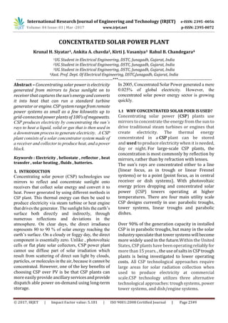
2.1 Parabolic trough collector
A parabolic trough is a type of solar thermal
collector that is straight in one dimension and
curved as a parabola in the other two, lined with a
polished metal mirror.
[Fig. 1 Parabolic trough concentrating solarcollector]
The energy of sunlight which enters the mirror
parallel to its plane of symmetry is focused along
the focal line, where objects are positioned that
are intended to be heated. For example, food may
be placed at the focal line ofa trough, whichcauses
the food to be cooked when the trough is aimed so
the Sun is in its plane of symmetry. Further
information on the use of parabolic troughs for
cooking can be found in the article about solar
cookers.
For other purposes, there is often a tube,
frequently a Dewar tube, which runs the length of
the trough at its focal line. The mirror is oriented
so that sunlight which it reflects is concentrated
on the tube, which contains a fluid whichisheated
to a high temperature by the energy of the
sunlight. The hot fluid can be used for many
purposes. Often, it is piped to a heat engine, which
uses the heat energy to drive machinery or to
generate electricity. This solar energy collector is
the most common and best known type of
parabolic trough. The paragraphsbelowtherefore
concentrate on this type.
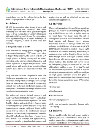
2.2 Linear Fresnel collector technologies
Linear concentrating collector fields consist of a
large number of collectorsin parallelrowsthat are
typically aligned in a north-south orientation to
maximize annual and summer energy collection.
With a single-axis sun-tracking system, this
configuration enables the mirrors to track the sun
from east to west during the day, which ensures](https://image.slidesharecdn.com/irjet-v4i3616-180106061656/85/Concentrated-Solar-Power-Plant-2-320.jpg)
![International Research Journal of Engineering and Technology (IRJET) e-ISSN: 2395 -0056
Volume: 04 Issue: 03 | Mar -2017 www.irjet.net p-ISSN: 2395-0072
© 2017, IRJET | Impact Factor value: 5.181 | ISO 9001:2008 Certified Journal | Page 2351
that the sun reflects continuously onto the
receiver tubes.
[Fig. 2 Linear Fresnel collector technologies]
Linearsystemsmayincorporate thermal storage.
In these systems, the collector field is oversized to
heat a storage system during the day so the
additional steam it generates can be used to
produce electricity in the eveningorduringcloudy
weather. These plants can also be designed as
hybrids, meaning that they use fossil fuel to
supplement the solar output duringperiodsoflow
solar radiation. In such a design, a natural gas-
fired heater or gas-steam boiler/reheater is used.
In the future, linear systems may be integrated
with existing or new combined-cycle natural-gas-
and coal-fired plants.
2.3 Solar tower technology
Power tower systems alsocalledcentralreceivers,
use many large, flat heliostats (mirrors) to track
the sun and focus its rays onto a receiver. As
shown in Figure 3, the receiver sits on top of a tall
tower in which concentratedsunlight heatsa fluid,
such as molten salt, as hot as 1,050°F. The hot fluid
can be used immediately to make steam for
electricity generation or stored for later use.
Molten salt retains heat efficiently, so it can be
stored for days before being converted into
electricity. That means electricitycan be produced
during periods of peak need on cloudy days or
even several hours after sunset.
[Fig.3 Solar tower technology]
2.4 Strilling dish technology
[Fig.4 Strilling dish technology]
Dish/engine systems use mirroreddishes(about
10 times larger than a backyard satellite dish) to
focus and concentrate sunlight onto a receiver. As
shown in Figure 5, the receiver is mounted at the
focal point of the dish. To capture the maximum
amount of solar energy, the dish assembly tracks
the sun across the sky. The receiver is integrated
into a high-efficiency "external" combustion
engine. The engine has thin tubes containing
hydrogen or helium gas that run along the outside
of the engine's four piston cylinders and open into
the cylinders. As concentrated sunlight fallson the
receiver, it heats the gas in the tubes to very high
temperatures, which causes hot gas to expand
inside the cylinders. The expanding gas drives the](https://image.slidesharecdn.com/irjet-v4i3616-180106061656/85/Concentrated-Solar-Power-Plant-3-320.jpg)
![International Research Journal of Engineering and Technology (IRJET) e-ISSN: 2395 -0056
Volume: 04 Issue: 03 | Mar -2017 www.irjet.net p-ISSN: 2395-0072
© 2017, IRJET | Impact Factor value: 5.181 | ISO 9001:2008 Certified Journal | Page 2352
pistons. The pistons turn a crankshaft, which
drives an electric generator. The receiver, engine,
and generator comprise a single, integrated
assembly mounted at the focus of the mirrored
dish.
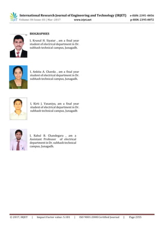
3. Working
The system uses proprietary software to control
thousands of tracking mirrors, known as
heliostats, to directly concentrate sunlight onto a
boiler filled with water that sits atop a tower.
When the sunlight hits the boiler, the water inside
is heated and creates high temperature steam.
Once produced, the steam is used either in a
conventional turbine to produce electricity or in
industrial process applications, such as thermal
enhanced oil recovery (EOR).
By integrating conventional power block
components, such as turbines, with our
proprietary technology and next-generation solar
field design, projects using our systems are able to
deliver cost-competitive, reliable andclean power
when needed most. In addition, by integrating our
technology with natural gas or other fossil fuels
through a process referred to as hybridization,
projects using our systems are able to further
increase output and reliability.
[ F i g . 5 S c h e m a t i c d i a g r a m
o f a s t e a m c y c l e p o w e r
p l a n t w i t h a p a r a b o l i c
t r o u g h c o l l e c t o r a n d a
t h e r m a l e n e r g y s t o r a g e
( S o u r c e : D L R ) ]
4. CSP
4.1 Absorber
Each type of CSP technology has its own absorber
design. Parabolic troughs andFresnelsystemsuse
linear receiver tubes composed of an external
glass tube (coated to ensure high solar
transmittance) and an internal metallic pipe
(coated to ensure high solar absorption). Towers
use central receivers. The towers currently in
operation in Spain (PS10 and PS20) have a cavity
receiver, formed of four vertical metallic panes in
which saturated steam circulates. The panes are
coated to increase solar absorption and arranged
in a semi-cylindrical shape to minimize radiation
and convection losses.
4.2 Heat transfer
All CSP technologies use heat transfer fluids
(HTFs) to transfer the heat generated in the
receivers to the power conversion unit(s).
Parabolic troughs use synthetic oil with a
maximum operating temperature of about 400°C.
Future developments are around improved
synthetic oil, molten salts or steam which allow
higher temperatures.
Fresnel systems also use synthetic oils or
water/steam. Tower systems use superheated
steam or molten salt. Future developments are
around gases (air, hydrogen, helium and carbon
dioxide) and liquid metals.
Dish systems can also reach high temperatures,
and use Stirling engines with gas (hydrogen or
helium) as the working fluid.
4.3 Thermal storage
An important attribute of CSP is the ability to
integrate thermalstorage. Todate, thishasmainly
been for operational purposes, providing 3060
minutes of full-load storage. Plants are now being
designed for 67.5 hours of full-load storage, which
is enough to allow operation wellintothe evening.
The solar field needs to be oversized so that heat](https://image.slidesharecdn.com/irjet-v4i3616-180106061656/85/Concentrated-Solar-Power-Plant-4-320.jpg)
![International Research Journal of Engineering and Technology (IRJET) e-ISSN: 2395 -0056
Volume: 04 Issue: 03 | Mar -2017 www.irjet.net p-ISSN: 2395-0072
© 2017, IRJET | Impact Factor value: 5.181 | ISO 9001:2008 Certified Journal | Page 2354
harmfulemissionsandwithout anyfuelcostsSolar
thermal power plants with integrated molten salt
energy storage can operate 24/7, proving
baseload power for both on-grid and off-grid
applications Integrated energy storage provides
the ability to shift electricity generation to meet
different profile needs and deliver firm, reliable
power at high capacity value Molten salt thermal
energy storage is the lowest capital cost energy
storage system Solar thermal power plants with
integrated energy storage are cost-competitive
with any new build coal, natural gas, or nuclear
technology Storage allows the facility to produce
more than twice as much net annual output
(megawatt hours) than any othersolartechnology
Firm output ensures a more stable and secure
transmission system.
6. Advantages of CSP
One major competitive advantage of concentrated
solar power systems is that they closely resemble
most of the current power plants. For example,
much of the equipment nowusedforconventional,
centralized power plants running on fossil
fuels can also be used for concentrated solar
power plants. CSP simply substitutes the use of
concentrated solar power instead of combustible
fossil fuels to produce electricity. This means that
concentrated solar power can be integrated fairly
easily into today’s electric utility grid. This also
makes concentrated solar power technology the
most cost-effective solar option for large-scale
electricity generation.
Environmental benefits of concentrated solar
power
A huge environmental benefit that should not be
overlooked is that simple and non-polluting
concentrated solar power technology can be
deployed relatively quickly and can contribute
substantially to reducing carbon dioxide
emissions. Each concentrated solar power plant
provides emissions reductions compared to its
natural gas counterpart; the 4,000MWscenarioin
this study offsets at least 300 tons per year of NOx
emissions, 180 tons of CO emissions per year, and
7,600,000 tons per year of CO2.
However, the costofthese technologiesisstillhigh
to enter the global market on a larger scale, and
needs to decrease before such an entry can be
possible. Today, concentrated solar power
technology has a cost somewhere between those
of Photovoltaics and wind (1W=4EUR).
Consequently, additional large-scale research
efforts are necessary to further advance
concentrated solar power technology to make it
profitable and compatible as an alternative source
of clean energy.
REFERENCES
[1] Hans Müller-steinhagen freng and franz trieb
(2004), concentrating solar power, institute of
technical thermodynamics, german aerospace
centre (dlr), stuttgart, germany
[2] Lovegrove, K.; Pye, J. Fundamental principles of
concentrating solar power {(CSP)} systems. In
ConcentratingSolarPowerTechnology:Principles,
Developments and Applications; Lovegrove, K.,
Stein, W., Eds.; Woodhead Publishing:
Philadelphia, PA, USA, 2012; Chapter 2,pp. 16–67.
[3] Morin, G. Optimisation of concentrating solar
power (CSP) plant designs through integrated
techno-economic modelling. In Concentrating
Solar Power Technology: Principles,
Developments and Applications; Lovegrove, K.,
Stein, W., Eds.; Woodhead Publishing:
Philadelphia, PA, USA, 2012; Chapter 16, pp. 495–
535.
[4] Buck, R., Bräuning, T., Denk, T., Pfänder, M.,
Schwarzbözl, P., Tellez, F.(2002)‘Solar-hybridgas
turbinebased power tower systems (REFOS)’, J.
Solar Energy Engineering, 124, 2–9
[5] Bockamp, S., Griestop, T., Fruth, M., Ewert, M.,
Lerchenmüller, H., Mertins, M., Morin, G., Häberle,
A.,Dersch, J. (2003) Solar Thermal Power
Generation (Fresnel),PowerGen.](https://image.slidesharecdn.com/irjet-v4i3616-180106061656/85/Concentrated-Solar-Power-Plant-6-320.jpg)

The document summarizes concentrated solar power (CSP) technology. It discusses four main CSP designs - parabolic troughs, tower systems, linear troughs, and parabolic dishes. Parabolic troughs are the most common currently, making up over 90% of installed CSP generation capacity. Tower systems are expected to become more widely used. Molten salt is highlighted as an important development, allowing CSP plants to operate at higher temperatures and efficiencies while enabling thermal energy storage for electricity generation after sunset or when solar irradiance is low.


