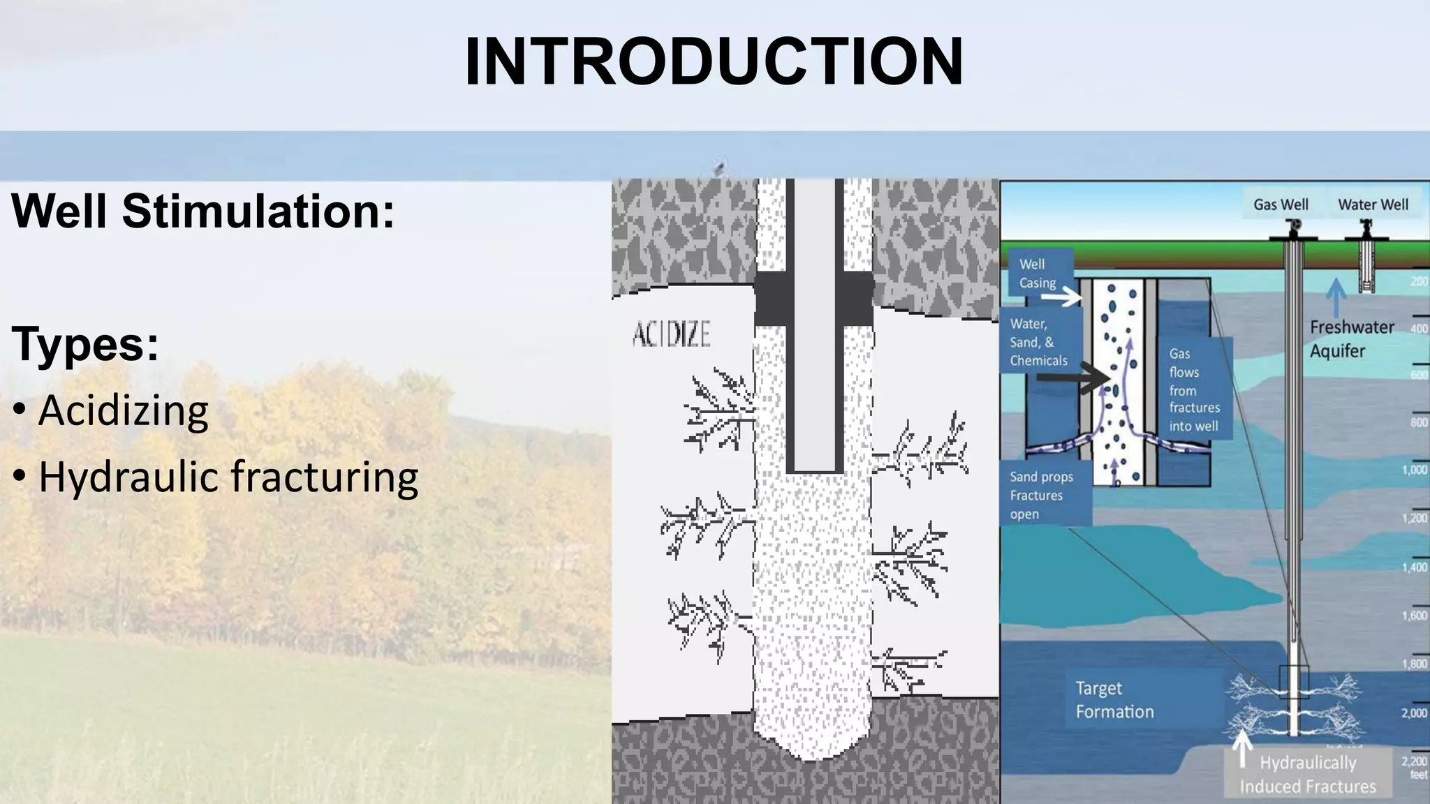
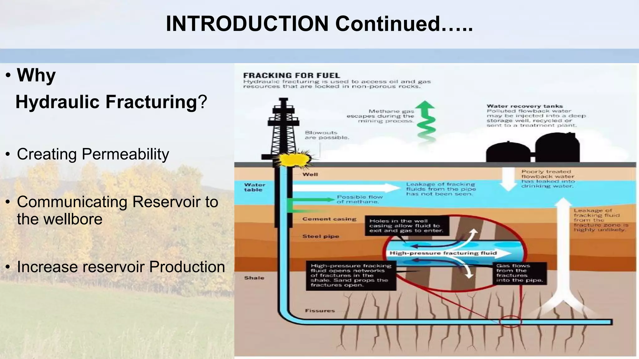
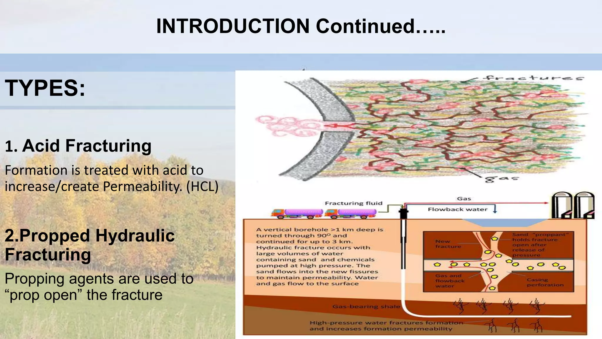
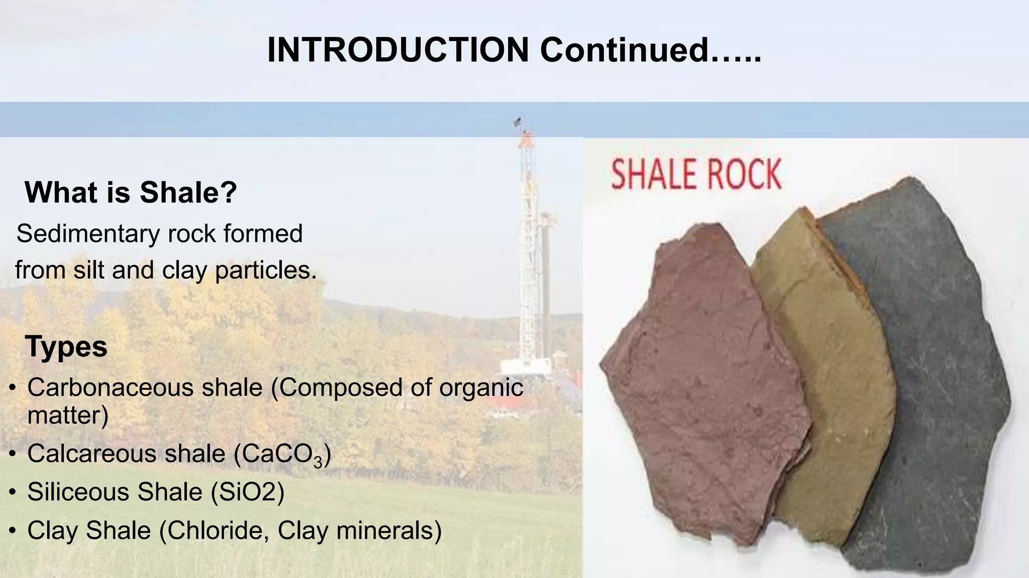
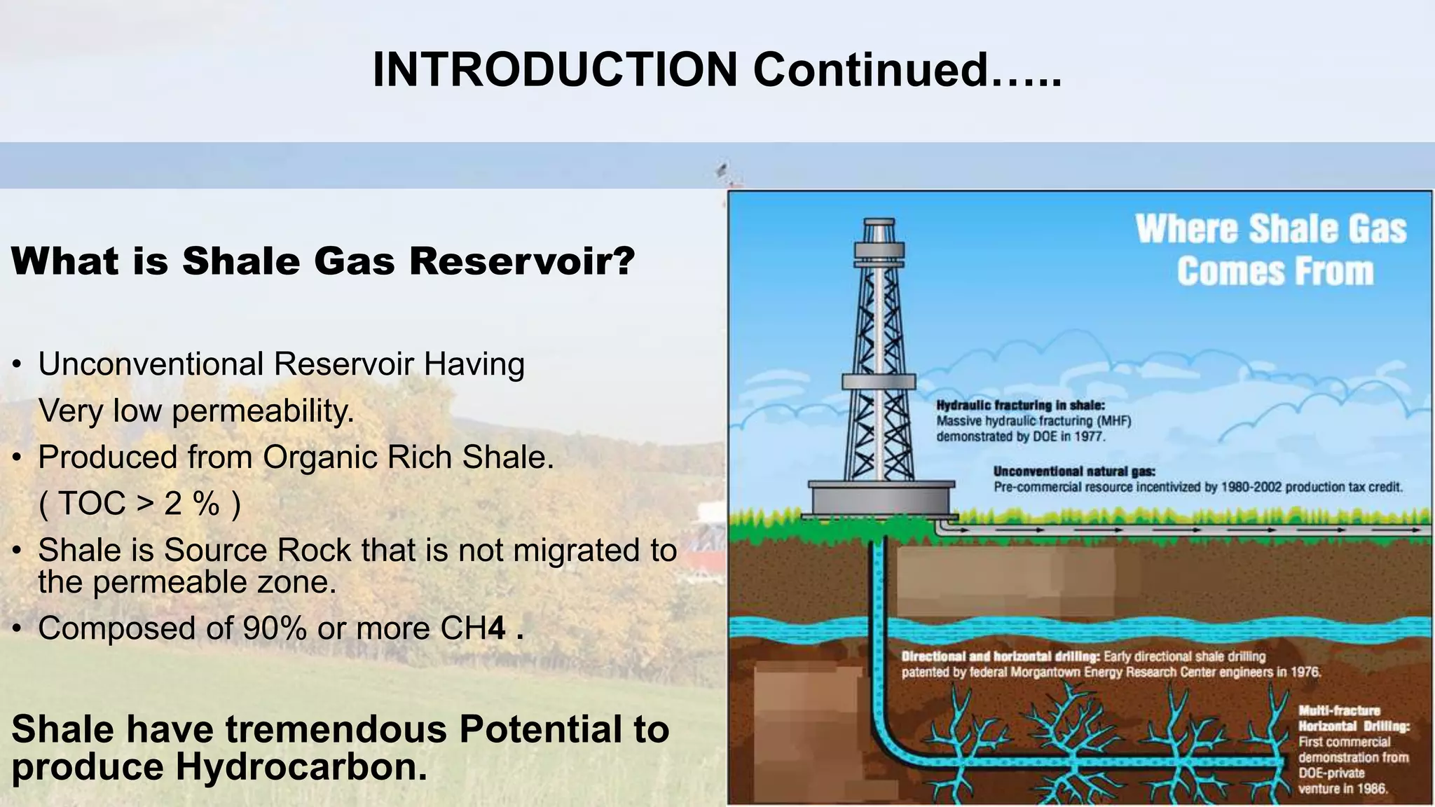
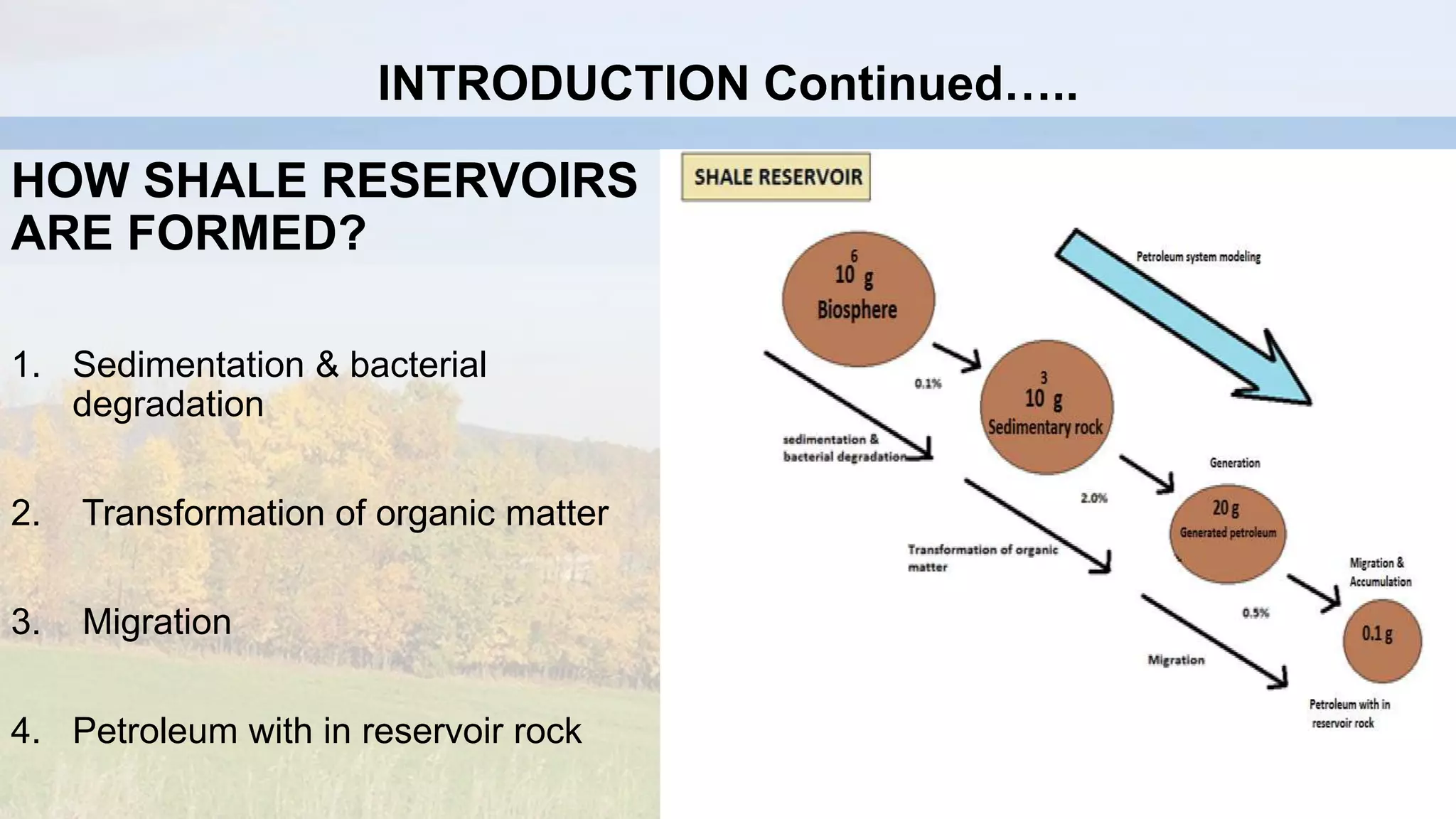
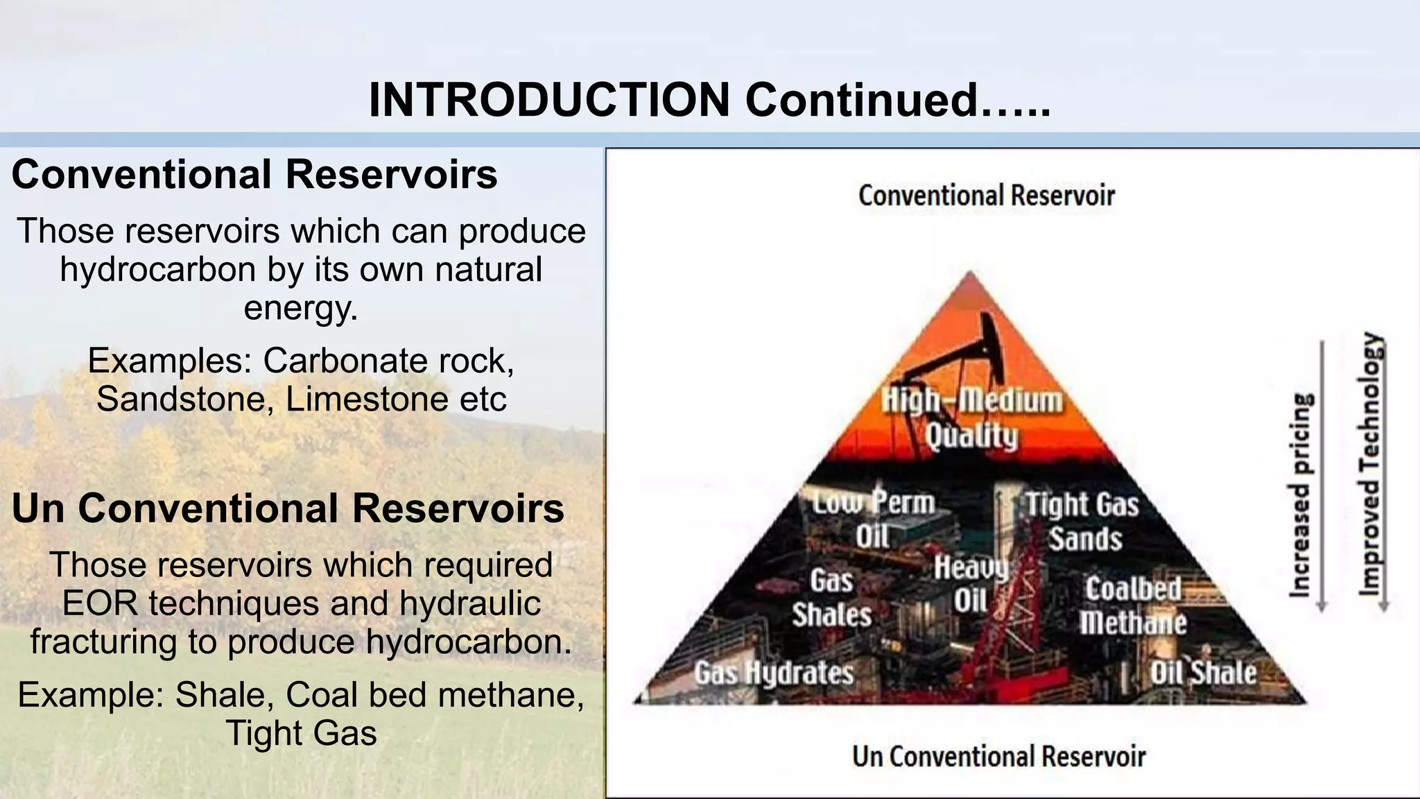
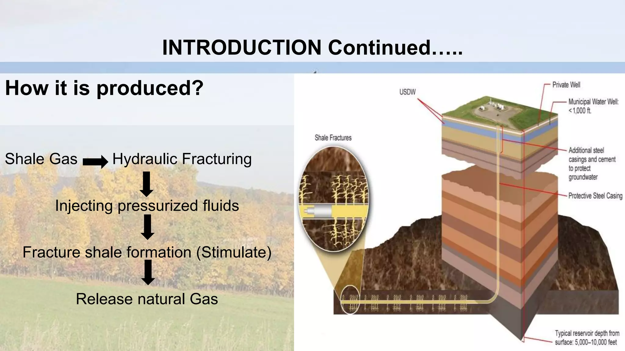
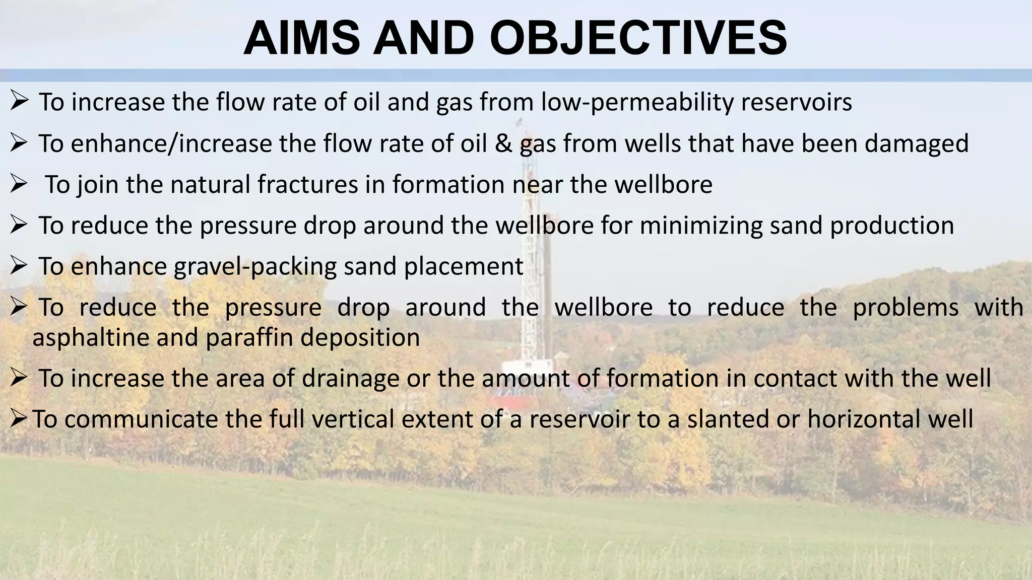
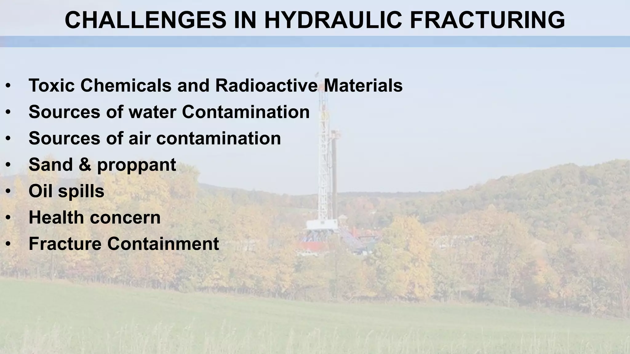
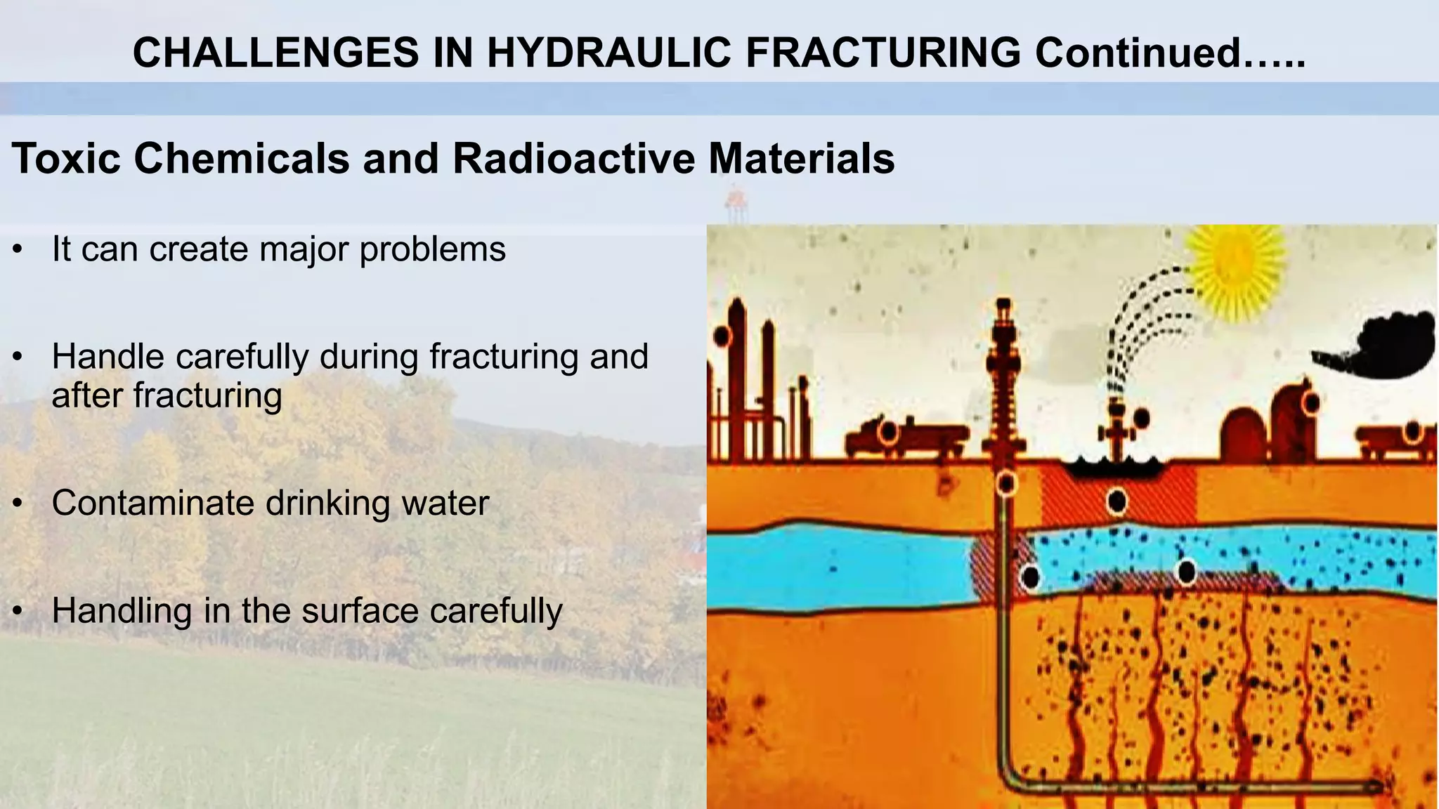
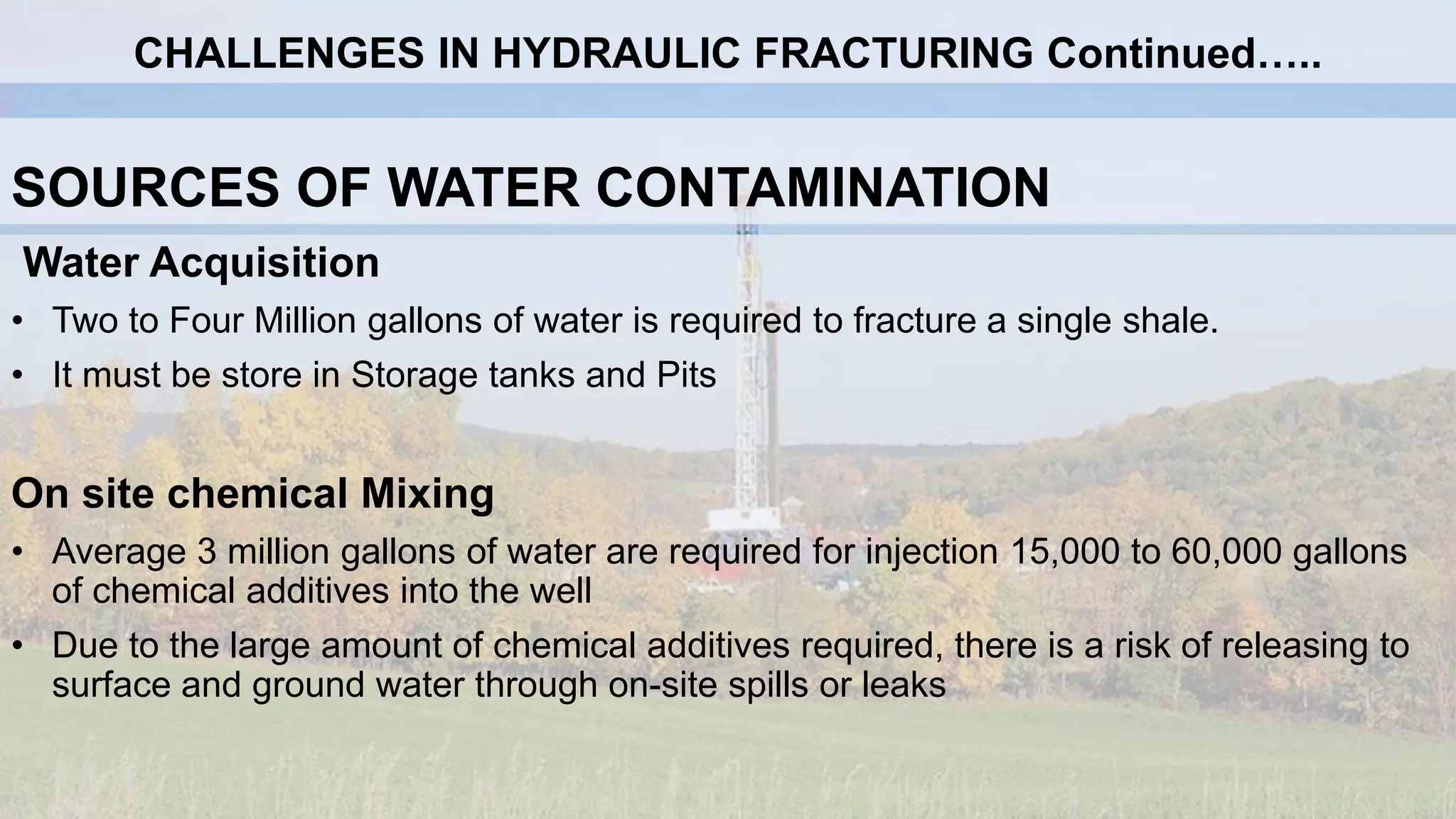
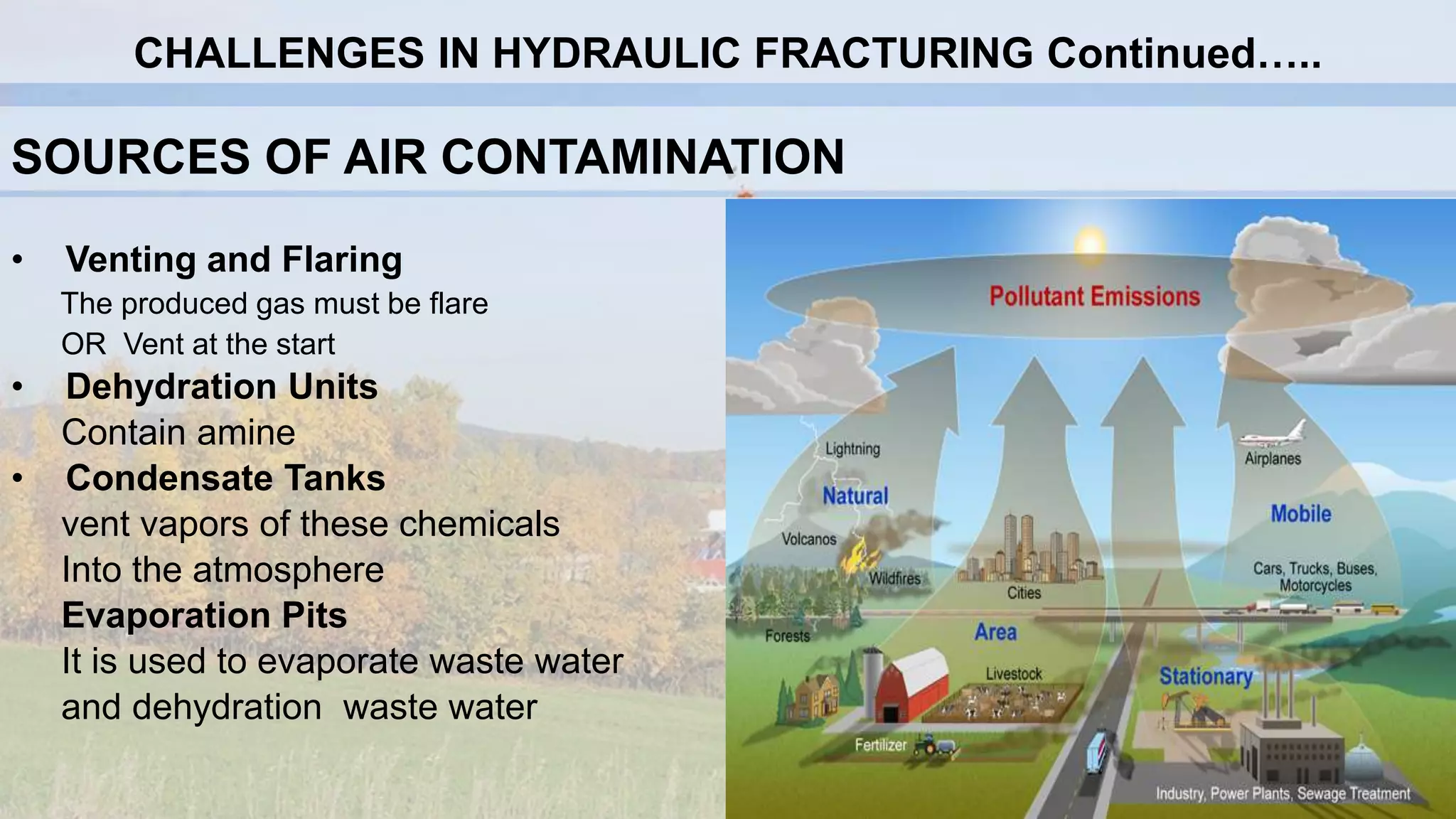
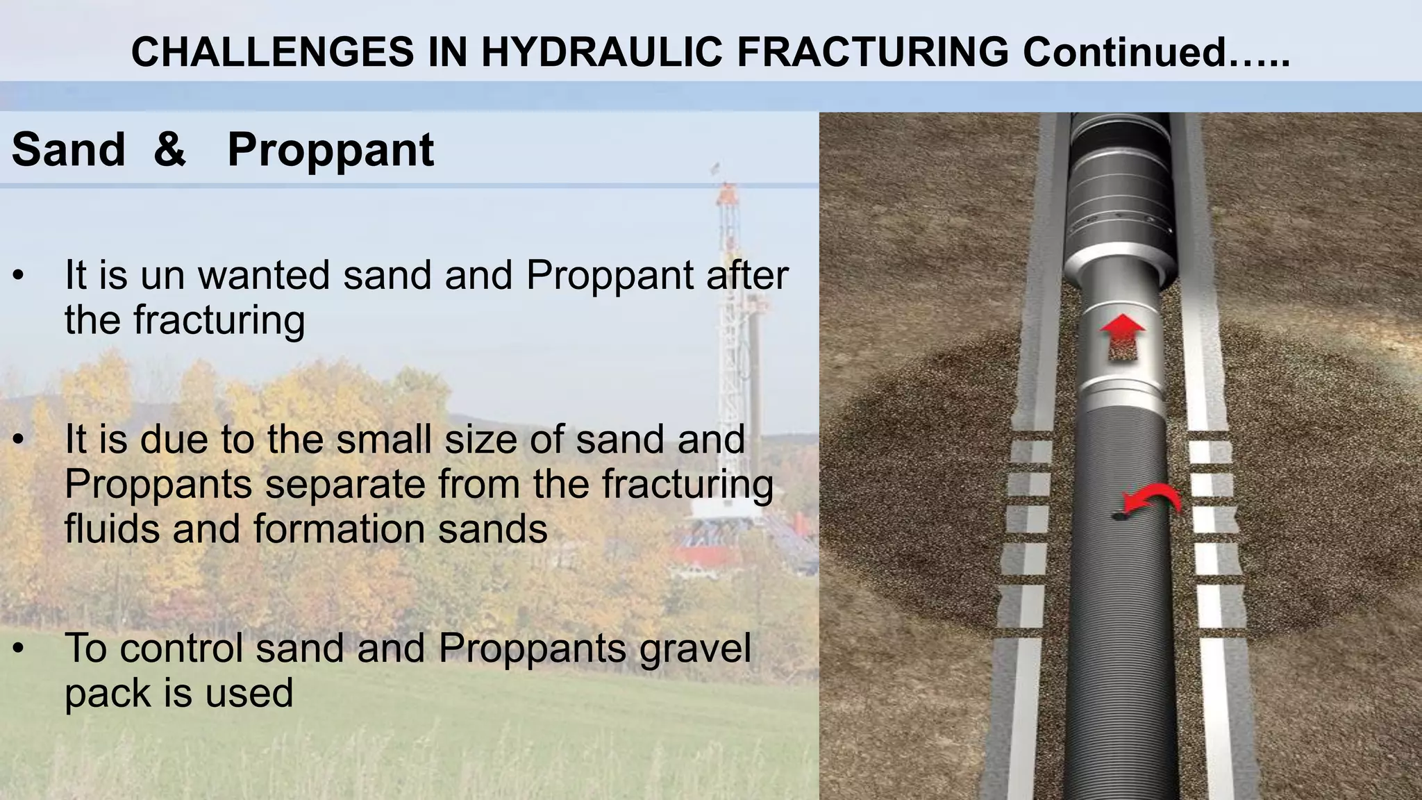
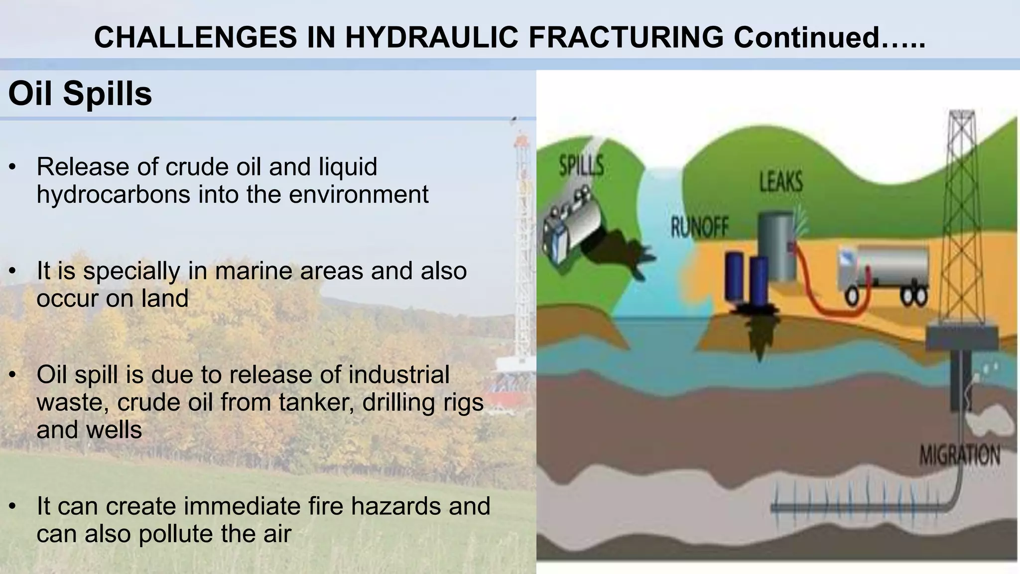
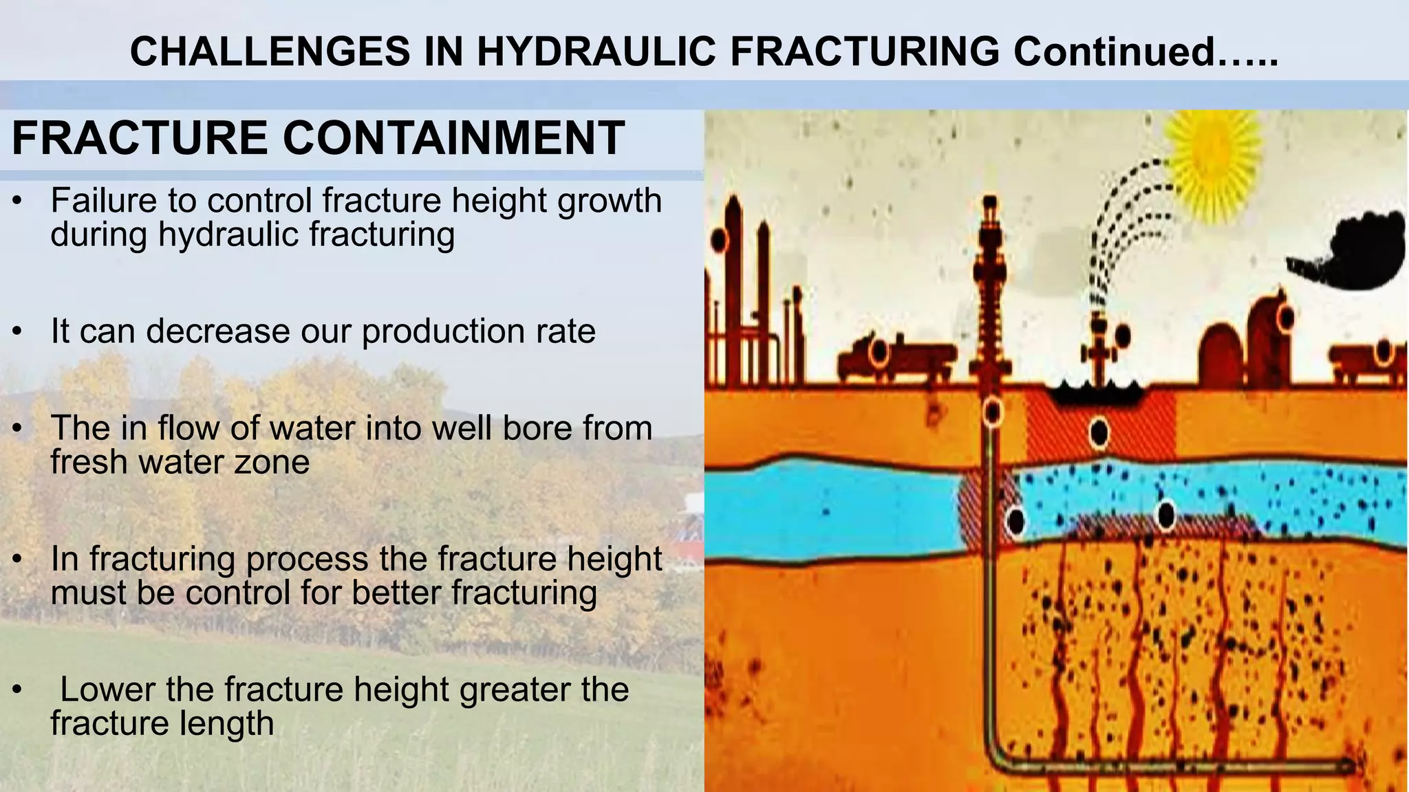
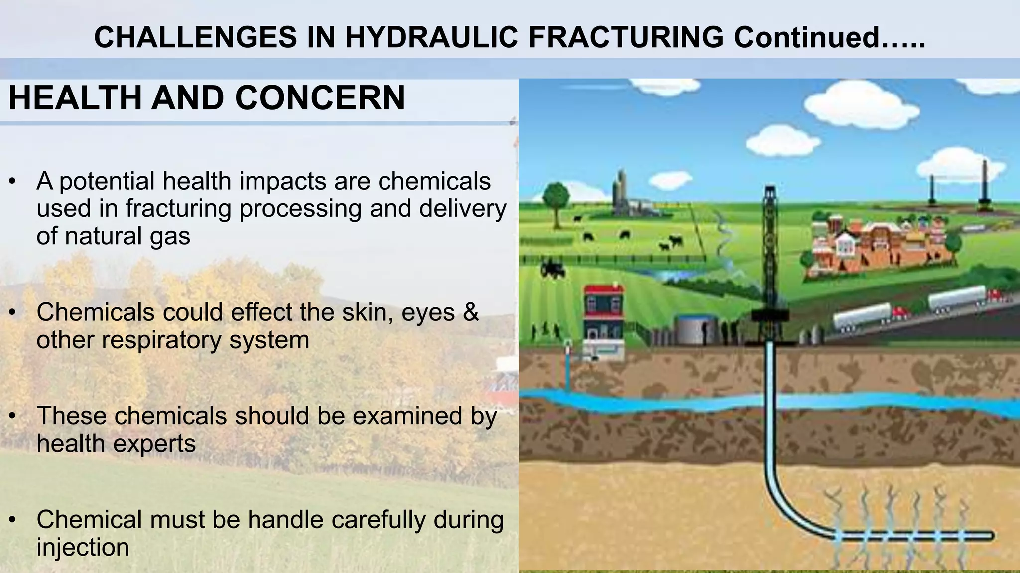
FINAL SEMINAR
“PRODUCTION OPTIMIZATION BY HYDRAULIC
FRACTURING IN SHALE GAS RESERVOIR”
Department of Petroleum & Gas Engineering
Faculty of Engineering
Balochistan University of Information Technology, Engineering & Management Sciences, Quetta
28th August, 2015
GROUP SUPERVISIOR
Engr. Azizullah Shaikh
GROUP MEMBERS
Kamran Khan Kakar (19633)
Syed Siraj Ahmed (16849)
Syed Israrullah (18649)
Bilal Ahmed (17757)
Ahmel Khan (16201)
Muhammad Tariq (18109)
OUTLINES
• Introduction
• Aims and Objectives
• Scope of Project
• Literature Review
• Methodology
• Results and Analysis
• Conclusion and Recommendation
• References
INTRODUCTION
Well Stimulation:
Types:
• Acidizing
• Hydraulic fracturing
INTRODUCTION Continued…..
• Why
Hydraulic Fracturing?
• Creating Permeability
• Communicating Reservoir to
the wellbore
• Increase reservoir Production
TYPES:
1. Acid Fracturing
Formation is treated with acid to
increase/create Permeability. (HCL)
2.Propped Hydraulic
Fracturing
Propping agents are used to
“prop open” the fracture
INTRODUCTION Continued…..
What is Shale?
Sedimentary rock formed
from silt and clay particles.
Types
• Carbonaceous shale (Composed of organic
matter)
• Calcareous shale (CaCO3)
• Siliceous Shale (SiO2)
• Clay Shale (Chloride, Clay minerals)
INTRODUCTION Continued…..
What is Shale Gas Reservoir?
• Unconventional Reservoir Having
Very low permeability.
• Produced from Organic Rich Shale.
( TOC > 2 % )
• Shale is Source Rock that is not migrated to
the permeable zone.
• Composed of 90% or more CH4 .
Shale have tremendous Potential to
produce Hydrocarbon.
INTRODUCTION Continued…..
HOW SHALE RESERVOIRS
ARE FORMED?
1. Sedimentation & bacterial
degradation
2. Transformation of organic matter
3. Migration
4. Petroleum with in reservoir rock
INTRODUCTION Continued…..
Conventional Reservoirs
Those reservoirs which can produce
hydrocarbon by its own natural
energy.
Examples: Carbonate rock,
Sandstone, Limestone etc
Un Conventional Reservoirs
Those reservoirs which required
EOR techniques and hydraulic
fracturing to produce hydrocarbon.
Example: Shale, Coal bed methane,
Tight Gas
INTRODUCTION Continued…..
How it is produced?
Shale Gas Hydraulic Fracturing
Injecting pressurized fluids
Fracture shale formation (Stimulate)
Release natural Gas
INTRODUCTION Continued…..
AIMS AND OBJECTIVES
 To increase the flow rate of oil and gas from low-permeability reservoirs
 To enhance/increase the flow rate of oil & gas from wells that have been damaged
 To join the natural fractures in formation near the wellbore
 To reduce the pressure drop around the wellbore for minimizing sand production
 To enhance gravel-packing sand placement
 To reduce the pressure drop around the wellbore to reduce the problems with
asphaltine and paraffin deposition
 To increase the area of drainage or the amount of formation in contact with the well
To communicate the full vertical extent of a reservoir to a slanted or horizontal well
SCOPE OF PROJECT
To improve groundwater wells
As a means of enhancing waste remediation, usually hydrocarbon waste
or spills
 To dispose waste product by injection deep into rock
To measure stress/force in the Earth
For electricity generation in increasing geothermal systems
To enhance injection rates for geologic sequestration of CO2
LITERATURE REVIEW
• Stanolind Oil and Gas Co. in (1948)
• J.B Clark (1949)
• 100,000 hydraulic fracturing treatments (1955)
• Kansas (1947) performed while Veach reported (1989) for approximately 10,000
gallons on NAPALM
LITERATURE REVIEW Continued…
History of Hydraulic Frac: Through Shale Formation In Pakistan
• In 2009 Survey, Pakistan stands 19th through out the world in shale reserves
(51 Trillion Cubic Feet)
• EIA in 2011 established that estimates of 52 Trillion Cubic Feet of shale reserves in
Pakistan
• Pakistan is left with 23 TCF of Natural gas reserves and they are expected to deplete
in 2025 so then only possibility to hit Shale Reservoirs
Location of Shale Reserves in Pakistan
• Under the Punjab and majority mainly upper Sindh province of Pakistan
• khyber Pakhtunkhwa, under the Indus basin region, predominantly Ranikot and
Sembar
• The future of the basin is an important Baluchistan basin and northern Indus basin
along with south Indus basin and the central Indus River basin
GLOBAL PRESPECTIVE OF SHALE OIL & GAS
DEVELOPMENT
Shale oil and gas reserve in major countries Shale Oil and Gas Reserves in major Countries of Asia
Countries Recoverable Shale
Oil Reserves,
(Billion Barrels)
Recoverable
Shale Gas
Reserves,
(Trillion cu-ft)
USA 58 862
Argentina 27 802
Australia 18 437
Venezuela 13 11
Mexico 13 681
Canada 8.8 388
Algeria n/a 707
South Africa n/a 485
UK 0.7 26
Countries
Technically
Recoverable Shale
Oil Reserves
(Billion Barrels)
Technically
Recoverable Shale
Gas Reserves
(Trillion cu-ft)
China 32 1275
Indonesia 7.9 574
Pakistan 9.1 51
Libya 26 290
India n/a 63
HYDRAULIC FRACTURING ADDITIVES
S.no Additives type Description of purpose Examples of chemical
1. Prop pant Props open the fracture and allows fluid to flow of
more freely to the wellbore
1. Centered bauxite.
2. zirconium oxide.
3. Ceramic beads.
2. Acids Cleans up perforation HCl (3 to 28 %)
3. Braker Reduces the viscosity of fluid Per oxi desulphates
4. Corrosion Inhibitors Reduces rust formation on steel tubing Bi-shulphate for oxygen scavengers
5. Cross linkers Used to increase fluid viscosity Potassium hydroxide,Borate salt
6. Friction reducer Allow fracture fluid to be injected at optimum rates
and pressure by minimizing friction
Petroleum distillates
7. jellying agents Increases fracturing fluid viscosity Petroleum distillates
8. Iron control Prevents carbonates and sulphates from plugging
off the formation
Ammonium chloride, Ethylene glycol
9. Solvent Used to control wettability of contact surfaces Various aromatic hydrocarbon
10. Surfactants Used to reduce surface tension b/w two fluid methanol
FRACTURING FLUIDS AND CONDITIONS FOR THEIR USE
Base Fluid Fluid Type Main Composition Used For
Water
Linear
Cross-linked
Micellar
Guar,
Cross-linker+Guar,HPG, CMHPG or CMHEC
Electrolyte and Surfactant
Short Fractures, low temperature
Long Fractures, High temperature
Moderate length fractures, moderate
temperature.
Foam
Water Based
Acid Based
Alcohol Based
Foamer+N2 Or CO2
Foamer + N2
Methanol + Foamer+ N2
Low Pressure Formations
Low Pressure, Carbonate formations
Low Pressure, water-sensitive formations
Oil
Linear
Cross-linked
Water Emulsion
Gelling Agent
Gelling Agent + Cross-linker
Water+ Oil + Emulsifier
Short fractures, water sensitive formations
Long fractures, water sensitive formations
Moderate length fractures, good fluid loss control.
Acid
Linear
Cross-linked
Oil Emulsion
Guar or HPG
Cross-linker + Guar + HPG
Acid + Oil + Emulsifier
Short fractures, Carbonate formations
Longer, wider fractures, Carbonate formations
Moderate length fractures, Carbonate formations
Slick Water
Slick water is a fresh or saline water containing high molecular weight polymers that inhibit turbulence and reduce pressure loss due to
turbulent fluid as they are pumped into the formation. Slick water is most effective in hard, brittle shale.
VARIOUS FLUID REQUIRED FOR HYDRAULIC FRACTURING
TREATMENT
• Oil based Frac Fluids: To avoid the freezing of injected fluid in cold weather (Gasoline, Kerosene and Diesel oil)
• Water based Frac Fluids: The additive are easily soluble, it is cheaper & easily available than other fluids
• Alcohol based frac Fluids: They are used to open the plugged channels to release the gas from shale
• Acid Frac Fluids: Limestone and dolomite are dissolved by acid fracturing treatment
• Surfactants: Used to reduce surface tension b/w two fluids.(Methanol)
• Clay Stabilizers: To protect formation from swelling
• Polymers: It is used to viscosified the fracture fluid
• Viscosity breaker: It is used to reduce the viscosity
• Biocides: It is used to stop the growth of algae, fungi and bacteria
• Slick water Additives: That stop the turbulence and reduce pressure loss
• Toxic Chemicals and Radioactive Materials
• Sources of water Contamination
• Sources of air contamination
• Sand & proppant
• Oil spills
• Health concern
• Fracture Containment
CHALLENGES IN HYDRAULIC FRACTURING
Toxic Chemicals and Radioactive Materials
• It can create major problems
• Handle carefully during fracturing and
after fracturing
• Contaminate drinking water
• Handling in the surface carefully
CHALLENGES IN HYDRAULIC FRACTURING Continued…..
SOURCES OF WATER CONTAMINATION
Water Acquisition
• Two to Four Million gallons of water is required to fracture a single shale.
• It must be store in Storage tanks and Pits
On site chemical Mixing
• Average 3 million gallons of water are required for injection 15,000 to 60,000 gallons
of chemical additives into the well
• Due to the large amount of chemical additives required, there is a risk of releasing to
surface and ground water through on-site spills or leaks
CHALLENGES IN HYDRAULIC FRACTURING Continued…..
SOURCES OF WATER CONTAMINATION Cont…..
• Well Injection
Proper casing and cementing job must be done in well
• Flow back and Produced
Flow back containing the initial fracking fluids as well as naturally occurring toxic and
radioactive substances return to the surface
• Waste water Treatment and Waste Disposal
The flow back waste water is either reused or discharged to surface water
CHALLENGES IN HYDRAULIC FRACTURING Continued…..
SOURCES OF AIR CONTAMINATION
• Venting and Flaring
The produced gas must be flare
OR Vent at the start
• Dehydration Units
Contain amine
• Condensate Tanks
vent vapors of these chemicals
Into the atmosphere
Evaporation Pits
It is used to evaporate waste water
and dehydration waste water
CHALLENGES IN HYDRAULIC FRACTURING Continued…..
Sand & Proppant
• It is un wanted sand and Proppant after
the fracturing
• It is due to the small size of sand and
Proppants separate from the fracturing
fluids and formation sands
• To control sand and Proppants gravel
pack is used
CHALLENGES IN HYDRAULIC FRACTURING Continued…..
Oil Spills
• Release of crude oil and liquid
hydrocarbons into the environment
• It is specially in marine areas and also
occur on land
• Oil spill is due to release of industrial
waste, crude oil from tanker, drilling rigs
and wells
• It can create immediate fire hazards and
can also pollute the air
CHALLENGES IN HYDRAULIC FRACTURING Continued…..
FRACTURE CONTAINMENT
• Failure to control fracture height growth
during hydraulic fracturing
• It can decrease our production rate
• The in flow of water into well bore from
fresh water zone
• In fracturing process the fracture height
must be control for better fracturing
• Lower the fracture height greater the
fracture length
CHALLENGES IN HYDRAULIC FRACTURING Continued…..
HEALTH AND CONCERN
• A potential health impacts are chemicals
used in fracturing processing and delivery
of natural gas
• Chemicals could effect the skin, eyes &
other respiratory system
• These chemicals should be examined by
health experts
• Chemical must be handle carefully during
injection
CHALLENGES IN HYDRAULIC FRACTURING Continued…..
METHODOLOGY
FRACTURING EQUIPMENTS:
Fracturing-fluid tanks
• Hold/store Fluids
• Fluid tanks are available in several
shapes and sizes
• Tanks are lined to prevent iron from
hydraulic fracturing
BULK HANDLING EQUIPMENTS FOR HANDLING
• It is used to transport proppant to the
blender
• Capacity is between 2000-4000 cubic feet
• On the basis of gravity the proppant feed
into the blender
FRACTURING EQUIPMENTS Continued
Fluid/Proppant Proportioners
• Liquid /proppant proportioners are also
called blenders
• They are used to transmit all the pre-
mixed fluid, different liquids, dehydrated
additives and proppant
• Inject high pressure into down hole
FRACTURING EQUIPMENTS Continued
PUMPING UNITS
• Conventional Pumps are used to supply the
essential horsepower to produce and to extend
the required fracture
• Conventional pumps are used for a pressure
from( 0 - 10,000 psi)
• Conventional pumps if used for long pump
times (more than 2 hours)
FRACTURING EQUIPMENTS Continued
INJECTION MANIFOLD/HEADERS
• Connecting each unit to the mixer
• The high-pressure treatment line to the well
head
• Top suction manifolds are used to close the
mixer to the pump units
• Attach the pump to properly treat line
FRACTURING EQUIPMENTS Continued
WELLHEAD ISOLATION
• High pressure, corrosive fluids and
Proppant damage wellhead
• Specialized instrument insulation is
used to protect Christmas tree
wellhead from damage
• A rubber cup assembly of mandrel
seals to the tubing walls and protect
the tree from fluid and pressure
• Wellhead isolation tools are available
to manage pressure up to 20,000 psi
FRACTURING EQUIPMENTS Continued
HORIZONTAL DRILLING & HYDRAULIC FRACTURING
• Used to maximize well contact with
target hydrocarbon reservoirs
• Used to increase hydraulic connectivity
within the formation
• To produce economic quantities of oil
and gas from low-permeability
formations
CASE STUDIES
Case Study No: 1
Hydraulic fracturing in the Dutch
Posedonia Shale
• Vertical well and horizontal well
drilling
• Posedonia shale has porosity up to
10 % and Permeability 10 nD
• Comparative study between Dutch
Posedonia shale and three shale
gases in USA
RESULTS AND ANALYSIS
Effect of fracture spacing in
complete partially propped
fracture
• Increasing the number of stages will
decrease the distance between these
clusters
• Many American shales are brittle and
hard, but if a shale is very soft there will
be no blocks to rotate and thus no self-
propping
CASE STUDIES Continued….
Case Study No: 1 Continued…
Results from Case Study No:1
• Dutch Posedonia having high TOC and porosity is good candidate for shale
gas production
• Result suggested that it is having high young modulus, low poison ratio and
low stress anisotropy
• Posedonia shale is very soft and require high viscous fracturing fluid
• Large Stimulated reservoir volume by increase in fracture density to enhance
fracture conductivity
• More testing on samples are performed to reduce uncertainty
CASE STUDIES Continued….
Case Study No: 2
Hydraulic Fracturing design
and the use of qualitative data
(Eagle Ford Gas-Shale)
• Stimulation to the flow of hydrocarbon in
all shale formation is not in the same
manner.
• Major qualitative components of fracture
design are:
1. Reservoir Characterization
2. Design Consideration
Pretreatment Flow Data
Choke size inches WHP
psi
BHP psi Q(mmscfd
)
PI scfd/psi
0.5 inches 1513 2075 09 7435
0.625 inches 1145 1761 11 6910
0.75 inches 868 1545 12 6373
Post-treatment Flow Data
Chock size inches WHP
psi
BHP psi Q(mm
scfd)
PI scfd/psi Increase
PI
0.5 inches 2092 2764 13 1917 158%
0.625 inches 1739 2534 17 1657 140%
0.75 inches 1419 2375 20 15052 136%
CASE STUDIES Continued….
• Reservoir properties of Eagle ford shale from core
data
• Larger mesh size proppant were used to maintain
conductivity of fracture channel
Parameters Unit Range
Total organic
Carbon
% 2 – 9
Porosity % 8 -18
Water saturation % 7 – 31
Permeability Nano dacrcies 20 – 1, 200
Static young’s
modulus
Pounds / square
inch
1.00 E+ 06 –
2.50 E 06
Poisson ratio 0.25 – 0.27
CASE STUDIES Continued….
Case Study No: 2 Continued…
Hydraulic Fracturing design and the
use of qualitative data (Eagle Ford
Gas-Shale)
• At the beginning of fracture treatment, both fluid injection rate (Qinj) and specific design
fluid viscosity µ of the frac fluid are essential to create required system of fracture
• Ductile shale, such that most of eagle fork requires highly viscous fracturing fluid
• Shallow reservoir depths allow placement of high concentration (4lbs/gallon) of large
mesh proppant (20/40 mesh) with slick water; but deeper depths require more viscous
fluids
• Large proppant size having higher conductivity is used for liquid gas production.
• Proppant embedment, crushed proppants, formation fines and proppant digenesis may
have major impact on conductivity with time
• Surface modifying agents such as surfactants, cross linker, inhibiters can help to
minimize the effect of slow proppant-pack conductivity with time
Results from Case Study No:2
CASE STUDIES Continued….
Case Study No: 3
Optimizing Hydraulic Fracturing
Performance in Northeastern
United States Fractured Shale
Formations
• Comparison studies of micro emulsion system
with conventional surfactants (CS) when
injected into shale
• Identifying effectiveness of micro emulsion vs
conventional surfactants (CS) in regaining
permeability
• Presenting and production data where
multiphase fluid treatments have improved
fluid recoveries
CASE STUDIES Continued….
Case Study No: 3 Continued…
Optimizing Hydraulic Fracturing
Performance in Northeastern
United States Fractured Shale
Formations
• Reservoir and production information from
24 wells
• All 24 wells were treated
 23,000 bbl of water
 110,000 lb of 40/70 sand
 250,000 lb of 20/40 sand tail in at 65 BPM
CS
wells
Top
Pert
Bottom
Pert
h (ft) k
(mD)
kh
(mD-ft)
ISIP-
15m
Calc k Calc kh
1 6896 7196 300 0.002 0.6 104 0.0021 0.63
2 6823 7130 307 0.002 0.614 100 0.0017 0.79
3 6776 7104 328 0.002 0.656 80 0.0026 1.07
4 6944 7296 352 0.002 0.704 253 0.0014 0.73
5 6870 7220 350 0.002 0.7 111 0.0006 0.30
6 6743 7038 295 0.002 0.56 297 0.0010 0.30
7 7285 7642 357 0.002 0.714 106 0.0031 1.10
8 6822 7116 294 0.002 0.588 33 0.0059 1.71
9 6862 7170 308 0.002 0.616 70 0.0059 1.71
10 6854 7175 321 0.002 0.642 200 0.0012 0.36
11 7144 7500 356 0.002 0.712 73 0.0034 1.11
12 6940 7244 333 0.002 0.608 290 0.0019 0.54
MA
Wells
1 7400 7756 331 0.002 0.712 42 0.0046 1.64
2 6823 7156 314 0.002 0.666 123 0.0070 1.74
3 6812 7134 319 0.002 0.644 40 0.0041 1.50
4 6879 7210 289 0.002 0.662 140 0.0059 1.89
5 6788 7102 327 0.002 0.628 140 0.0009 0.29
6 6845 7164 333 0.002 0.638 100 0.0060 1.79
7 6811 7100 336 0.002 0.578 285 0.0041 1.18
8 7073 7400 319 0.002 0.654 250 0.0021 0.54
9 6781 7114 312 0.002 0.666 220 0.0030 1.00
10 6960 7296 322 0.002 0.672 220 0.0029 1.00
11 6981 7300 295 0.002 0.638 41 0.0052 1.69
CASE STUDIES Continued….
• Study compiling data on Devonian shale formation and Rhine Street shale formation
showing there on attributes and characteristics.
• Core data displace that water saturation is decrease, Relative permeability to gas is
increased and capillary pressure is cut in half when micro emulsion is introduced.
• Low permeability core clean up test show that pressure to start cleanup is reduced by
50% and regained permeability to gas is doubled.
• The addition of micro emulsion to fracturing treatment as resulted in 50 % increase in
recoveries of gas production.
Results from Case Study No:3
CASE STUDIES Continued….
CONCLUSION AND RECOMMENDATIONS
Conclusion:
• To measure and approach to reduce land disturbance and land-take
• To measure and to reduce noise during drilling, fracturing and completion
• To measure to address water resource depletion
• To measure to reduce the negative effects caused by increased traffic movements
• To improve well integrity and to reduce the risk of ground and surface water
contamination
• To reduce the pressure on biodiversity
CONCLUSION AND RECOMMENDATIONS
Recommendations:
• To use of micro-seismic monitoring in relation to hydraulic fracturing
• To determine chemical interactions between fracturing fluids and different shale rocks,
and displacement of formation fluids
• To induce seismicity triggered by hydraulic fracturing
• to improve well integrity through development of better casing and cementing methods
and practices
• To research into the risks and causes of methane migration to groundwater from shale
gas extraction
• To develop a system of voluntary ecological initiatives within sensitive habitats
• Proper guidance, effective equipment and installations are operated that will assist
and prevent different hazards from the human as well as environment and atmosphere
REFERENCES
Erle C .Donaldson Waqai Alam and Nasreen Begum Tetrahedron, Inc; hydraulic
fracturing explained
 Economides J. Michael , Hill A. Daniel, Petroleum Production Systems, 1993
 Economides, M. J., Nolte, K. G., 2000: “Reservoir Stimulation (3rd ed.)”. John Wiley &
sons, Ltd., Chichester, England, UK
M . JANSZEN, delft university of technology ; T bakker well engineering partners; P.L.J
zitha, Delft University of technology, binga Energy
Production Technology II Module, Heriot Watt University, UK, 2007, by Dr. David
Davies.
Shale oil and gas life line for Pakistan by Engr Arshad H.Abbasi
Talbot D.M, Hemke K.A. and Leshchshyn T.H: “Stimulation Fracture Height Control
above Water or Depleted Zones,” SPE 60318, presented in Rocky Mountain
Regional/Low Permeability Reservoirs Symposium, Denver, Colorado, 12 – 15 March
2000.
REFERENCES
Wine J.D, DeBonis M.P. and Thomas R.L: “The Effect of Guar and HPG Cross linked
Fracturing Fluids on Well Performance: A Case Study,” SPE 18969, presented in
Rocky Mountain Regional/Low Permeability Reservoirs Symposium, Denver,
Colorado, 6 – 8 March 1989.
 Vidic, R.D., Brantley, S.L., Vandenbosshe, J.M., Yoxtheimer, D., and Abad, J.D., 2013.
Impact of Shale Gas Development on Regional Water Quality. Science Vol. 340, 17
May 2103.
 Westgaard, G., 2002. Securing a License to Operate: The Role of Corporate Social
Responsibility. 17th World Petroleum Congress, September 1-5, 2002, Rio de Janeiro,
Brazil. Conference Paper 32406.
Zimmerman, M, Patterson, K., Hedgcoxe, H.R, and Houghton, J., 2013. Groundwater
Monitoring in the Eagle Ford: Evaluating Baseline Conditions in a Risk Management
Context. SPE Americas E&P Health, Safety, Security and Environmental Conference,
Galveston, Texas, USA, 18-20 March 2013. SPE 163763.
Develop Success From Failures. Discouragement and
Failures are two of the Surest stepping stones to Success

Final Presentation (2)

  • 2.
    FINAL SEMINAR “PRODUCTION OPTIMIZATIONBY HYDRAULIC FRACTURING IN SHALE GAS RESERVOIR” Department of Petroleum & Gas Engineering Faculty of Engineering Balochistan University of Information Technology, Engineering & Management Sciences, Quetta 28th August, 2015
  • 3.
    GROUP SUPERVISIOR Engr. AzizullahShaikh GROUP MEMBERS Kamran Khan Kakar (19633) Syed Siraj Ahmed (16849) Syed Israrullah (18649) Bilal Ahmed (17757) Ahmel Khan (16201) Muhammad Tariq (18109)
  • 4.
    OUTLINES • Introduction • Aimsand Objectives • Scope of Project • Literature Review • Methodology • Results and Analysis • Conclusion and Recommendation • References
  • 5.
  • 6.
    INTRODUCTION Continued….. • Why HydraulicFracturing? • Creating Permeability • Communicating Reservoir to the wellbore • Increase reservoir Production
  • 7.
    TYPES: 1. Acid Fracturing Formationis treated with acid to increase/create Permeability. (HCL) 2.Propped Hydraulic Fracturing Propping agents are used to “prop open” the fracture INTRODUCTION Continued…..
  • 8.
    What is Shale? Sedimentaryrock formed from silt and clay particles. Types • Carbonaceous shale (Composed of organic matter) • Calcareous shale (CaCO3) • Siliceous Shale (SiO2) • Clay Shale (Chloride, Clay minerals) INTRODUCTION Continued…..
  • 9.
    What is ShaleGas Reservoir? • Unconventional Reservoir Having Very low permeability. • Produced from Organic Rich Shale. ( TOC > 2 % ) • Shale is Source Rock that is not migrated to the permeable zone. • Composed of 90% or more CH4 . Shale have tremendous Potential to produce Hydrocarbon. INTRODUCTION Continued…..
  • 10.
    HOW SHALE RESERVOIRS AREFORMED? 1. Sedimentation & bacterial degradation 2. Transformation of organic matter 3. Migration 4. Petroleum with in reservoir rock INTRODUCTION Continued…..
  • 11.
    Conventional Reservoirs Those reservoirswhich can produce hydrocarbon by its own natural energy. Examples: Carbonate rock, Sandstone, Limestone etc Un Conventional Reservoirs Those reservoirs which required EOR techniques and hydraulic fracturing to produce hydrocarbon. Example: Shale, Coal bed methane, Tight Gas INTRODUCTION Continued…..
  • 12.
    How it isproduced? Shale Gas Hydraulic Fracturing Injecting pressurized fluids Fracture shale formation (Stimulate) Release natural Gas INTRODUCTION Continued…..
  • 13.
    AIMS AND OBJECTIVES To increase the flow rate of oil and gas from low-permeability reservoirs  To enhance/increase the flow rate of oil & gas from wells that have been damaged  To join the natural fractures in formation near the wellbore  To reduce the pressure drop around the wellbore for minimizing sand production  To enhance gravel-packing sand placement  To reduce the pressure drop around the wellbore to reduce the problems with asphaltine and paraffin deposition  To increase the area of drainage or the amount of formation in contact with the well To communicate the full vertical extent of a reservoir to a slanted or horizontal well
  • 14.
    SCOPE OF PROJECT Toimprove groundwater wells As a means of enhancing waste remediation, usually hydrocarbon waste or spills  To dispose waste product by injection deep into rock To measure stress/force in the Earth For electricity generation in increasing geothermal systems To enhance injection rates for geologic sequestration of CO2
  • 15.
    LITERATURE REVIEW • StanolindOil and Gas Co. in (1948) • J.B Clark (1949) • 100,000 hydraulic fracturing treatments (1955) • Kansas (1947) performed while Veach reported (1989) for approximately 10,000 gallons on NAPALM
  • 16.
    LITERATURE REVIEW Continued… Historyof Hydraulic Frac: Through Shale Formation In Pakistan • In 2009 Survey, Pakistan stands 19th through out the world in shale reserves (51 Trillion Cubic Feet) • EIA in 2011 established that estimates of 52 Trillion Cubic Feet of shale reserves in Pakistan • Pakistan is left with 23 TCF of Natural gas reserves and they are expected to deplete in 2025 so then only possibility to hit Shale Reservoirs Location of Shale Reserves in Pakistan • Under the Punjab and majority mainly upper Sindh province of Pakistan • khyber Pakhtunkhwa, under the Indus basin region, predominantly Ranikot and Sembar • The future of the basin is an important Baluchistan basin and northern Indus basin along with south Indus basin and the central Indus River basin
  • 17.
    GLOBAL PRESPECTIVE OFSHALE OIL & GAS DEVELOPMENT Shale oil and gas reserve in major countries Shale Oil and Gas Reserves in major Countries of Asia Countries Recoverable Shale Oil Reserves, (Billion Barrels) Recoverable Shale Gas Reserves, (Trillion cu-ft) USA 58 862 Argentina 27 802 Australia 18 437 Venezuela 13 11 Mexico 13 681 Canada 8.8 388 Algeria n/a 707 South Africa n/a 485 UK 0.7 26 Countries Technically Recoverable Shale Oil Reserves (Billion Barrels) Technically Recoverable Shale Gas Reserves (Trillion cu-ft) China 32 1275 Indonesia 7.9 574 Pakistan 9.1 51 Libya 26 290 India n/a 63
  • 18.
    HYDRAULIC FRACTURING ADDITIVES S.noAdditives type Description of purpose Examples of chemical 1. Prop pant Props open the fracture and allows fluid to flow of more freely to the wellbore 1. Centered bauxite. 2. zirconium oxide. 3. Ceramic beads. 2. Acids Cleans up perforation HCl (3 to 28 %) 3. Braker Reduces the viscosity of fluid Per oxi desulphates 4. Corrosion Inhibitors Reduces rust formation on steel tubing Bi-shulphate for oxygen scavengers 5. Cross linkers Used to increase fluid viscosity Potassium hydroxide,Borate salt 6. Friction reducer Allow fracture fluid to be injected at optimum rates and pressure by minimizing friction Petroleum distillates 7. jellying agents Increases fracturing fluid viscosity Petroleum distillates 8. Iron control Prevents carbonates and sulphates from plugging off the formation Ammonium chloride, Ethylene glycol 9. Solvent Used to control wettability of contact surfaces Various aromatic hydrocarbon 10. Surfactants Used to reduce surface tension b/w two fluid methanol
  • 19.
    FRACTURING FLUIDS ANDCONDITIONS FOR THEIR USE Base Fluid Fluid Type Main Composition Used For Water Linear Cross-linked Micellar Guar, Cross-linker+Guar,HPG, CMHPG or CMHEC Electrolyte and Surfactant Short Fractures, low temperature Long Fractures, High temperature Moderate length fractures, moderate temperature. Foam Water Based Acid Based Alcohol Based Foamer+N2 Or CO2 Foamer + N2 Methanol + Foamer+ N2 Low Pressure Formations Low Pressure, Carbonate formations Low Pressure, water-sensitive formations Oil Linear Cross-linked Water Emulsion Gelling Agent Gelling Agent + Cross-linker Water+ Oil + Emulsifier Short fractures, water sensitive formations Long fractures, water sensitive formations Moderate length fractures, good fluid loss control. Acid Linear Cross-linked Oil Emulsion Guar or HPG Cross-linker + Guar + HPG Acid + Oil + Emulsifier Short fractures, Carbonate formations Longer, wider fractures, Carbonate formations Moderate length fractures, Carbonate formations Slick Water Slick water is a fresh or saline water containing high molecular weight polymers that inhibit turbulence and reduce pressure loss due to turbulent fluid as they are pumped into the formation. Slick water is most effective in hard, brittle shale.
  • 20.
    VARIOUS FLUID REQUIREDFOR HYDRAULIC FRACTURING TREATMENT • Oil based Frac Fluids: To avoid the freezing of injected fluid in cold weather (Gasoline, Kerosene and Diesel oil) • Water based Frac Fluids: The additive are easily soluble, it is cheaper & easily available than other fluids • Alcohol based frac Fluids: They are used to open the plugged channels to release the gas from shale • Acid Frac Fluids: Limestone and dolomite are dissolved by acid fracturing treatment • Surfactants: Used to reduce surface tension b/w two fluids.(Methanol) • Clay Stabilizers: To protect formation from swelling • Polymers: It is used to viscosified the fracture fluid • Viscosity breaker: It is used to reduce the viscosity • Biocides: It is used to stop the growth of algae, fungi and bacteria • Slick water Additives: That stop the turbulence and reduce pressure loss
  • 21.
    • Toxic Chemicalsand Radioactive Materials • Sources of water Contamination • Sources of air contamination • Sand & proppant • Oil spills • Health concern • Fracture Containment CHALLENGES IN HYDRAULIC FRACTURING
  • 22.
    Toxic Chemicals andRadioactive Materials • It can create major problems • Handle carefully during fracturing and after fracturing • Contaminate drinking water • Handling in the surface carefully CHALLENGES IN HYDRAULIC FRACTURING Continued…..
  • 23.
    SOURCES OF WATERCONTAMINATION Water Acquisition • Two to Four Million gallons of water is required to fracture a single shale. • It must be store in Storage tanks and Pits On site chemical Mixing • Average 3 million gallons of water are required for injection 15,000 to 60,000 gallons of chemical additives into the well • Due to the large amount of chemical additives required, there is a risk of releasing to surface and ground water through on-site spills or leaks CHALLENGES IN HYDRAULIC FRACTURING Continued…..
  • 24.
    SOURCES OF WATERCONTAMINATION Cont….. • Well Injection Proper casing and cementing job must be done in well • Flow back and Produced Flow back containing the initial fracking fluids as well as naturally occurring toxic and radioactive substances return to the surface • Waste water Treatment and Waste Disposal The flow back waste water is either reused or discharged to surface water CHALLENGES IN HYDRAULIC FRACTURING Continued…..
  • 25.
    SOURCES OF AIRCONTAMINATION • Venting and Flaring The produced gas must be flare OR Vent at the start • Dehydration Units Contain amine • Condensate Tanks vent vapors of these chemicals Into the atmosphere Evaporation Pits It is used to evaporate waste water and dehydration waste water CHALLENGES IN HYDRAULIC FRACTURING Continued…..
  • 26.
    Sand & Proppant •It is un wanted sand and Proppant after the fracturing • It is due to the small size of sand and Proppants separate from the fracturing fluids and formation sands • To control sand and Proppants gravel pack is used CHALLENGES IN HYDRAULIC FRACTURING Continued…..
  • 27.
    Oil Spills • Releaseof crude oil and liquid hydrocarbons into the environment • It is specially in marine areas and also occur on land • Oil spill is due to release of industrial waste, crude oil from tanker, drilling rigs and wells • It can create immediate fire hazards and can also pollute the air CHALLENGES IN HYDRAULIC FRACTURING Continued…..
  • 28.
    FRACTURE CONTAINMENT • Failureto control fracture height growth during hydraulic fracturing • It can decrease our production rate • The in flow of water into well bore from fresh water zone • In fracturing process the fracture height must be control for better fracturing • Lower the fracture height greater the fracture length CHALLENGES IN HYDRAULIC FRACTURING Continued…..
  • 29.
    HEALTH AND CONCERN •A potential health impacts are chemicals used in fracturing processing and delivery of natural gas • Chemicals could effect the skin, eyes & other respiratory system • These chemicals should be examined by health experts • Chemical must be handle carefully during injection CHALLENGES IN HYDRAULIC FRACTURING Continued…..
  • 30.
    METHODOLOGY FRACTURING EQUIPMENTS: Fracturing-fluid tanks •Hold/store Fluids • Fluid tanks are available in several shapes and sizes • Tanks are lined to prevent iron from hydraulic fracturing
  • 31.
    BULK HANDLING EQUIPMENTSFOR HANDLING • It is used to transport proppant to the blender • Capacity is between 2000-4000 cubic feet • On the basis of gravity the proppant feed into the blender FRACTURING EQUIPMENTS Continued
  • 32.
    Fluid/Proppant Proportioners • Liquid/proppant proportioners are also called blenders • They are used to transmit all the pre- mixed fluid, different liquids, dehydrated additives and proppant • Inject high pressure into down hole FRACTURING EQUIPMENTS Continued
  • 33.
    PUMPING UNITS • ConventionalPumps are used to supply the essential horsepower to produce and to extend the required fracture • Conventional pumps are used for a pressure from( 0 - 10,000 psi) • Conventional pumps if used for long pump times (more than 2 hours) FRACTURING EQUIPMENTS Continued
  • 34.
    INJECTION MANIFOLD/HEADERS • Connectingeach unit to the mixer • The high-pressure treatment line to the well head • Top suction manifolds are used to close the mixer to the pump units • Attach the pump to properly treat line FRACTURING EQUIPMENTS Continued
  • 35.
    WELLHEAD ISOLATION • Highpressure, corrosive fluids and Proppant damage wellhead • Specialized instrument insulation is used to protect Christmas tree wellhead from damage • A rubber cup assembly of mandrel seals to the tubing walls and protect the tree from fluid and pressure • Wellhead isolation tools are available to manage pressure up to 20,000 psi FRACTURING EQUIPMENTS Continued
  • 36.
    HORIZONTAL DRILLING &HYDRAULIC FRACTURING • Used to maximize well contact with target hydrocarbon reservoirs • Used to increase hydraulic connectivity within the formation • To produce economic quantities of oil and gas from low-permeability formations
  • 37.
    CASE STUDIES Case StudyNo: 1 Hydraulic fracturing in the Dutch Posedonia Shale • Vertical well and horizontal well drilling • Posedonia shale has porosity up to 10 % and Permeability 10 nD • Comparative study between Dutch Posedonia shale and three shale gases in USA RESULTS AND ANALYSIS
  • 38.
    Effect of fracturespacing in complete partially propped fracture • Increasing the number of stages will decrease the distance between these clusters • Many American shales are brittle and hard, but if a shale is very soft there will be no blocks to rotate and thus no self- propping CASE STUDIES Continued…. Case Study No: 1 Continued…
  • 39.
    Results from CaseStudy No:1 • Dutch Posedonia having high TOC and porosity is good candidate for shale gas production • Result suggested that it is having high young modulus, low poison ratio and low stress anisotropy • Posedonia shale is very soft and require high viscous fracturing fluid • Large Stimulated reservoir volume by increase in fracture density to enhance fracture conductivity • More testing on samples are performed to reduce uncertainty CASE STUDIES Continued….
  • 40.
    Case Study No:2 Hydraulic Fracturing design and the use of qualitative data (Eagle Ford Gas-Shale) • Stimulation to the flow of hydrocarbon in all shale formation is not in the same manner. • Major qualitative components of fracture design are: 1. Reservoir Characterization 2. Design Consideration Pretreatment Flow Data Choke size inches WHP psi BHP psi Q(mmscfd ) PI scfd/psi 0.5 inches 1513 2075 09 7435 0.625 inches 1145 1761 11 6910 0.75 inches 868 1545 12 6373 Post-treatment Flow Data Chock size inches WHP psi BHP psi Q(mm scfd) PI scfd/psi Increase PI 0.5 inches 2092 2764 13 1917 158% 0.625 inches 1739 2534 17 1657 140% 0.75 inches 1419 2375 20 15052 136% CASE STUDIES Continued….
  • 41.
    • Reservoir propertiesof Eagle ford shale from core data • Larger mesh size proppant were used to maintain conductivity of fracture channel Parameters Unit Range Total organic Carbon % 2 – 9 Porosity % 8 -18 Water saturation % 7 – 31 Permeability Nano dacrcies 20 – 1, 200 Static young’s modulus Pounds / square inch 1.00 E+ 06 – 2.50 E 06 Poisson ratio 0.25 – 0.27 CASE STUDIES Continued…. Case Study No: 2 Continued… Hydraulic Fracturing design and the use of qualitative data (Eagle Ford Gas-Shale)
  • 42.
    • At thebeginning of fracture treatment, both fluid injection rate (Qinj) and specific design fluid viscosity µ of the frac fluid are essential to create required system of fracture • Ductile shale, such that most of eagle fork requires highly viscous fracturing fluid • Shallow reservoir depths allow placement of high concentration (4lbs/gallon) of large mesh proppant (20/40 mesh) with slick water; but deeper depths require more viscous fluids • Large proppant size having higher conductivity is used for liquid gas production. • Proppant embedment, crushed proppants, formation fines and proppant digenesis may have major impact on conductivity with time • Surface modifying agents such as surfactants, cross linker, inhibiters can help to minimize the effect of slow proppant-pack conductivity with time Results from Case Study No:2 CASE STUDIES Continued….
  • 43.
    Case Study No:3 Optimizing Hydraulic Fracturing Performance in Northeastern United States Fractured Shale Formations • Comparison studies of micro emulsion system with conventional surfactants (CS) when injected into shale • Identifying effectiveness of micro emulsion vs conventional surfactants (CS) in regaining permeability • Presenting and production data where multiphase fluid treatments have improved fluid recoveries CASE STUDIES Continued….
  • 44.
    Case Study No:3 Continued… Optimizing Hydraulic Fracturing Performance in Northeastern United States Fractured Shale Formations • Reservoir and production information from 24 wells • All 24 wells were treated  23,000 bbl of water  110,000 lb of 40/70 sand  250,000 lb of 20/40 sand tail in at 65 BPM CS wells Top Pert Bottom Pert h (ft) k (mD) kh (mD-ft) ISIP- 15m Calc k Calc kh 1 6896 7196 300 0.002 0.6 104 0.0021 0.63 2 6823 7130 307 0.002 0.614 100 0.0017 0.79 3 6776 7104 328 0.002 0.656 80 0.0026 1.07 4 6944 7296 352 0.002 0.704 253 0.0014 0.73 5 6870 7220 350 0.002 0.7 111 0.0006 0.30 6 6743 7038 295 0.002 0.56 297 0.0010 0.30 7 7285 7642 357 0.002 0.714 106 0.0031 1.10 8 6822 7116 294 0.002 0.588 33 0.0059 1.71 9 6862 7170 308 0.002 0.616 70 0.0059 1.71 10 6854 7175 321 0.002 0.642 200 0.0012 0.36 11 7144 7500 356 0.002 0.712 73 0.0034 1.11 12 6940 7244 333 0.002 0.608 290 0.0019 0.54 MA Wells 1 7400 7756 331 0.002 0.712 42 0.0046 1.64 2 6823 7156 314 0.002 0.666 123 0.0070 1.74 3 6812 7134 319 0.002 0.644 40 0.0041 1.50 4 6879 7210 289 0.002 0.662 140 0.0059 1.89 5 6788 7102 327 0.002 0.628 140 0.0009 0.29 6 6845 7164 333 0.002 0.638 100 0.0060 1.79 7 6811 7100 336 0.002 0.578 285 0.0041 1.18 8 7073 7400 319 0.002 0.654 250 0.0021 0.54 9 6781 7114 312 0.002 0.666 220 0.0030 1.00 10 6960 7296 322 0.002 0.672 220 0.0029 1.00 11 6981 7300 295 0.002 0.638 41 0.0052 1.69 CASE STUDIES Continued….
  • 45.
    • Study compilingdata on Devonian shale formation and Rhine Street shale formation showing there on attributes and characteristics. • Core data displace that water saturation is decrease, Relative permeability to gas is increased and capillary pressure is cut in half when micro emulsion is introduced. • Low permeability core clean up test show that pressure to start cleanup is reduced by 50% and regained permeability to gas is doubled. • The addition of micro emulsion to fracturing treatment as resulted in 50 % increase in recoveries of gas production. Results from Case Study No:3 CASE STUDIES Continued….
  • 46.
    CONCLUSION AND RECOMMENDATIONS Conclusion: •To measure and approach to reduce land disturbance and land-take • To measure and to reduce noise during drilling, fracturing and completion • To measure to address water resource depletion • To measure to reduce the negative effects caused by increased traffic movements • To improve well integrity and to reduce the risk of ground and surface water contamination • To reduce the pressure on biodiversity
  • 47.
    CONCLUSION AND RECOMMENDATIONS Recommendations: •To use of micro-seismic monitoring in relation to hydraulic fracturing • To determine chemical interactions between fracturing fluids and different shale rocks, and displacement of formation fluids • To induce seismicity triggered by hydraulic fracturing • to improve well integrity through development of better casing and cementing methods and practices • To research into the risks and causes of methane migration to groundwater from shale gas extraction • To develop a system of voluntary ecological initiatives within sensitive habitats • Proper guidance, effective equipment and installations are operated that will assist and prevent different hazards from the human as well as environment and atmosphere
  • 48.
    REFERENCES Erle C .DonaldsonWaqai Alam and Nasreen Begum Tetrahedron, Inc; hydraulic fracturing explained  Economides J. Michael , Hill A. Daniel, Petroleum Production Systems, 1993  Economides, M. J., Nolte, K. G., 2000: “Reservoir Stimulation (3rd ed.)”. John Wiley & sons, Ltd., Chichester, England, UK M . JANSZEN, delft university of technology ; T bakker well engineering partners; P.L.J zitha, Delft University of technology, binga Energy Production Technology II Module, Heriot Watt University, UK, 2007, by Dr. David Davies. Shale oil and gas life line for Pakistan by Engr Arshad H.Abbasi Talbot D.M, Hemke K.A. and Leshchshyn T.H: “Stimulation Fracture Height Control above Water or Depleted Zones,” SPE 60318, presented in Rocky Mountain Regional/Low Permeability Reservoirs Symposium, Denver, Colorado, 12 – 15 March 2000.
  • 49.
    REFERENCES Wine J.D, DeBonisM.P. and Thomas R.L: “The Effect of Guar and HPG Cross linked Fracturing Fluids on Well Performance: A Case Study,” SPE 18969, presented in Rocky Mountain Regional/Low Permeability Reservoirs Symposium, Denver, Colorado, 6 – 8 March 1989.  Vidic, R.D., Brantley, S.L., Vandenbosshe, J.M., Yoxtheimer, D., and Abad, J.D., 2013. Impact of Shale Gas Development on Regional Water Quality. Science Vol. 340, 17 May 2103.  Westgaard, G., 2002. Securing a License to Operate: The Role of Corporate Social Responsibility. 17th World Petroleum Congress, September 1-5, 2002, Rio de Janeiro, Brazil. Conference Paper 32406. Zimmerman, M, Patterson, K., Hedgcoxe, H.R, and Houghton, J., 2013. Groundwater Monitoring in the Eagle Ford: Evaluating Baseline Conditions in a Risk Management Context. SPE Americas E&P Health, Safety, Security and Environmental Conference, Galveston, Texas, USA, 18-20 March 2013. SPE 163763.
  • 50.
    Develop Success FromFailures. Discouragement and Failures are two of the Surest stepping stones to Success