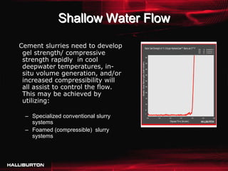
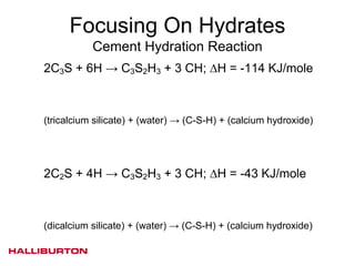
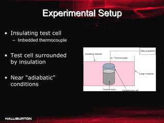
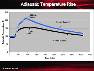
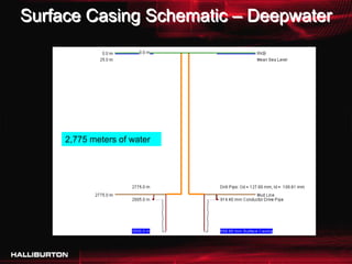
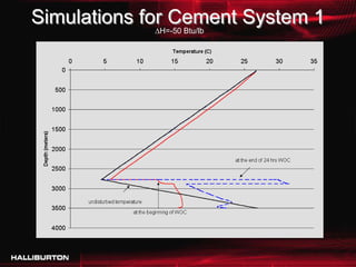
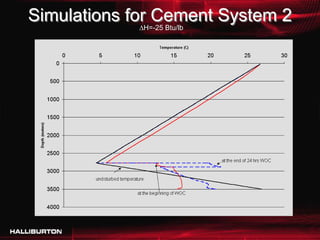
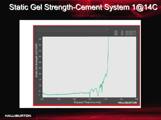
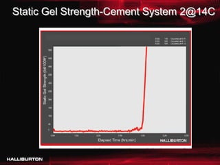
AADE Chapter Meeting
Deepwater Cementing Consideration
to Prevent Hydrates Destabilization

       F. Tahmourpour, Halliburton
   On behalf of Dr. Kris Ravi, Halliburton
                November 18, 2009
                    Houston
Overview

•   Background
•   Challenges
•   Solution
•   Results
•   Summary
Background

• Shallow Water Flow
  – Unconsolidated and relatively young geological formations that
    are shallow and have the potential for abnormally pressured
    saltwater sands, also known as SWF zones. Weak formations
    and pressured sands present very narrow margins between the
    frac pressure and pore pressure
• Gas Hydrates
  – Clathrate compounds, cage-type host structures in which single
    or multiple visitor molecules are trapped in the available space.
    The host molecule’s crystalline structure determines the
    structural design of the cage. This allows a molecule of methane
    get trapped inside a water molecule network. (3-D lattice 60 to
    180 times expansion)
Surface Casing Schematic – Deepwater


     2,775 meters of water
Shallow Water Flow

Cement slurries need to develop
 gel strength/ compressive
 strength rapidly in cool
 deepwater temperatures, in-
 situ volume generation, and/or
 increased compressibility will
 all assist to control the flow.
 This may be achieved by
 utilizing:

 – Specialized conventional slurry
   systems
 – Foamed (compressible) slurry
   systems
Hydrates
• Extremely large deposits of methane hydrates have
  been found under sediments on the ocean floors.

• About 6.4 trillion tons of methane gas is trapped in
  deposits of methane hydrates.

• Methane hydrate is a solid form of water containing
  large amounts of methane within its crystal
  structure.

• Methane hydrates are formed by migration of gas
  from great depths along geological faults, followed
  by precipitation, or crystallization, on contact of the
  rising gas stream with cold seawater.
Hydrate Stability
• Pressure, volume, and temperature (PVT)
  – When do hydrates become unstable?
  – Will cement hydration cause this outcome?
• 1 L methane hydrate downhole ~ 168 L
 Destabilizationgas at STP
  methane Zone
  – Gas release is a challenge for safety and
    economics
Known Gas Hydrates Around the World1


1
 Kvenvolden, K. 2001. Gas Hydrate Inventory on New Web Site. USGS Science for a Changing World,
February. http://soundwaves.usgs.gov/2001/02/research2.html.
Methane Hydrate Stability2


                      Methane Hydrate
                      Stability Curve


                      Geothermal Gradient


                  2
                   Hardage, B., Roberts, H. 2006. Gas Hydrate in
                  the Gulf of Mexico. What and Where is the
                  Seismic Target? The Leading Edge. May.
Challenges

• Shallow water flow may occur during or after cement job

• Under water blow out has happened

• Gas flow may occur after a cement job in deepwater
  environments that contain major hydrate zones.

• Destabilization of hydrates after the cement job is
  confirmed by downhole cameras.

• The gas flow could slow down in hours to days if the de-
  stabilization is not severe.

• However, the consequences could be more severe in worse
  cases.
Purpose
• Understand the factors contributing to the
  hydrates destabilization

• Analyze the effect of cement slurry heat of
  hydration on the annulus temperature (SWF
  and Hydrate destabilization)

• Design cement slurry to reduce the heat
  liberated during hydration while meeting the
  other objectives of deepwater cementing.

• Implement the optimized slurry in the field and
  monitor the results.
Deepwater Parameters

• Low fracture gradient

• Shallow water and gas-flow potential

• Low temperatures

• Narrow window between pore pressure and
  fracture gradient

• High rig cost
Deepwater Well Objectives
• Cement slurry should be placed in the entire
  annulus with no losses

• Temperature increase during slurry hydration
  should not destabilize hydrates

• There should be no influx of shallow water or gas
  into the annulus

• The cement slurry should develop strength in the
  shortest time after placement
               Conditions in deepwater wells are not
               conducive to achieving all of these
               objectives simultaneously
Focusing On Hydrates
           Cement Hydration Reaction
2C3S + 6H → C3S2H3 + 3 CH; ΔH = -114 KJ/mole


(tricalcium silicate) + (water) → (C-S-H) + (calcium hydroxide)


2C2S + 4H → C3S2H3 + 3 CH; ΔH = -43 KJ/mole


(dicalcium silicate) + (water) → (C-S-H) + (calcium hydroxide)
Experimental Setup

• Insulating test cell
   – Imbedded thermocouple


• Test cell surrounded
  by insulation

• Near “adiabatic”
  conditions
Adiabatic Temperature Rise
Surface Casing Schematic – Deepwater


     2,775 meters of water
Simulations for Cement System 1
              ΔH=-50 Btu/lb
Simulations for Cement System 2
              ΔH=-25 Btu/lb
Static Gel Strength-Cement System 1@14C
Static Gel Strength-Cement System 2@14C
Compressive Strength
• The cement slurry should develop compressive
  strength rapidly

• This is particularly important in the deepwater
  environment given the associated rig cost.

• At 14°C, Cement System 2 develops compressive
  strength (CS) of 350 psi in 10 hours and 800 psi
  in 24 hours.

• Cement System 1 develops 368 psi in 10 hours
  and 1,014 psi in 24 hours.
• Large size casings can be self supported very
  early on during CS development.
Summary 1 of 2
• SWF is a challenge that need to be planned for
  when designing slurry systems

• Both energized (foamed) slurries and
  conventional specialized slurries have been
  utilized successfully

• Destabilization of hydrates during cementing and
  production in deepwater environments is a
  challenge to the safety and economics
Summary 2 of 2
• Procedures to analyze and design cement slurries to lower
  the heat of hydration and help prevent the destabilization
  of the hydrates are presented.


• Data shows that optimizing slurry design reduces the
  adiabatic temperature rise – an indicator of the heat of
  hydration.


• The Cement System 2 with lower heat of hydration has
  been successfully implemented in the field and has helped
  to prevent destabilization of the hydrates.
Thanks
               ments
        ns/C om
Que stio

Halliburton Deepwater Cementing Presentation

  • 1.
    AADE Chapter Meeting DeepwaterCementing Consideration to Prevent Hydrates Destabilization F. Tahmourpour, Halliburton On behalf of Dr. Kris Ravi, Halliburton November 18, 2009 Houston
  • 2.
    Overview • Background • Challenges • Solution • Results • Summary
  • 3.
    Background • Shallow WaterFlow – Unconsolidated and relatively young geological formations that are shallow and have the potential for abnormally pressured saltwater sands, also known as SWF zones. Weak formations and pressured sands present very narrow margins between the frac pressure and pore pressure • Gas Hydrates – Clathrate compounds, cage-type host structures in which single or multiple visitor molecules are trapped in the available space. The host molecule’s crystalline structure determines the structural design of the cage. This allows a molecule of methane get trapped inside a water molecule network. (3-D lattice 60 to 180 times expansion)
  • 4.
    Surface Casing Schematic– Deepwater 2,775 meters of water
  • 5.
    Shallow Water Flow Cementslurries need to develop gel strength/ compressive strength rapidly in cool deepwater temperatures, in- situ volume generation, and/or increased compressibility will all assist to control the flow. This may be achieved by utilizing: – Specialized conventional slurry systems – Foamed (compressible) slurry systems
  • 6.
    Hydrates • Extremely largedeposits of methane hydrates have been found under sediments on the ocean floors. • About 6.4 trillion tons of methane gas is trapped in deposits of methane hydrates. • Methane hydrate is a solid form of water containing large amounts of methane within its crystal structure. • Methane hydrates are formed by migration of gas from great depths along geological faults, followed by precipitation, or crystallization, on contact of the rising gas stream with cold seawater.
  • 7.
    Hydrate Stability • Pressure,volume, and temperature (PVT) – When do hydrates become unstable? – Will cement hydration cause this outcome? • 1 L methane hydrate downhole ~ 168 L Destabilizationgas at STP methane Zone – Gas release is a challenge for safety and economics
  • 8.
    Known Gas HydratesAround the World1 1 Kvenvolden, K. 2001. Gas Hydrate Inventory on New Web Site. USGS Science for a Changing World, February. http://soundwaves.usgs.gov/2001/02/research2.html.
  • 9.
    Methane Hydrate Stability2 Methane Hydrate Stability Curve Geothermal Gradient 2 Hardage, B., Roberts, H. 2006. Gas Hydrate in the Gulf of Mexico. What and Where is the Seismic Target? The Leading Edge. May.
  • 10.
    Challenges • Shallow waterflow may occur during or after cement job • Under water blow out has happened • Gas flow may occur after a cement job in deepwater environments that contain major hydrate zones. • Destabilization of hydrates after the cement job is confirmed by downhole cameras. • The gas flow could slow down in hours to days if the de- stabilization is not severe. • However, the consequences could be more severe in worse cases.
  • 11.
    Purpose • Understand thefactors contributing to the hydrates destabilization • Analyze the effect of cement slurry heat of hydration on the annulus temperature (SWF and Hydrate destabilization) • Design cement slurry to reduce the heat liberated during hydration while meeting the other objectives of deepwater cementing. • Implement the optimized slurry in the field and monitor the results.
  • 12.
    Deepwater Parameters • Lowfracture gradient • Shallow water and gas-flow potential • Low temperatures • Narrow window between pore pressure and fracture gradient • High rig cost
  • 13.
    Deepwater Well Objectives •Cement slurry should be placed in the entire annulus with no losses • Temperature increase during slurry hydration should not destabilize hydrates • There should be no influx of shallow water or gas into the annulus • The cement slurry should develop strength in the shortest time after placement Conditions in deepwater wells are not conducive to achieving all of these objectives simultaneously
  • 14.
    Focusing On Hydrates Cement Hydration Reaction 2C3S + 6H → C3S2H3 + 3 CH; ΔH = -114 KJ/mole (tricalcium silicate) + (water) → (C-S-H) + (calcium hydroxide) 2C2S + 4H → C3S2H3 + 3 CH; ΔH = -43 KJ/mole (dicalcium silicate) + (water) → (C-S-H) + (calcium hydroxide)
  • 15.
    Experimental Setup • Insulatingtest cell – Imbedded thermocouple • Test cell surrounded by insulation • Near “adiabatic” conditions
  • 16.
  • 17.
    Surface Casing Schematic– Deepwater 2,775 meters of water
  • 18.
    Simulations for CementSystem 1 ΔH=-50 Btu/lb
  • 19.
    Simulations for CementSystem 2 ΔH=-25 Btu/lb
  • 20.
  • 21.
  • 22.
    Compressive Strength • Thecement slurry should develop compressive strength rapidly • This is particularly important in the deepwater environment given the associated rig cost. • At 14°C, Cement System 2 develops compressive strength (CS) of 350 psi in 10 hours and 800 psi in 24 hours. • Cement System 1 develops 368 psi in 10 hours and 1,014 psi in 24 hours. • Large size casings can be self supported very early on during CS development.
  • 23.
    Summary 1 of2 • SWF is a challenge that need to be planned for when designing slurry systems • Both energized (foamed) slurries and conventional specialized slurries have been utilized successfully • Destabilization of hydrates during cementing and production in deepwater environments is a challenge to the safety and economics
  • 24.
    Summary 2 of2 • Procedures to analyze and design cement slurries to lower the heat of hydration and help prevent the destabilization of the hydrates are presented. • Data shows that optimizing slurry design reduces the adiabatic temperature rise – an indicator of the heat of hydration. • The Cement System 2 with lower heat of hydration has been successfully implemented in the field and has helped to prevent destabilization of the hydrates.
  • 25.
    Thanks ments ns/C om Que stio