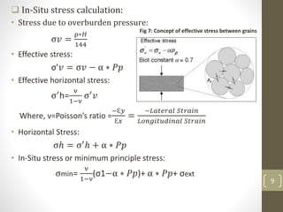
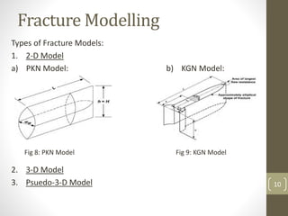
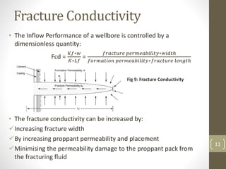
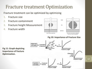
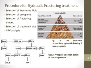
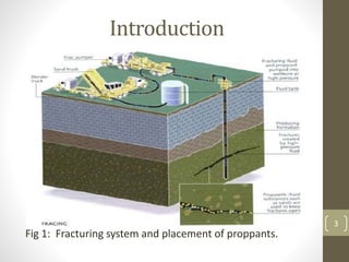
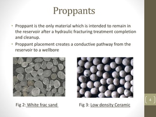
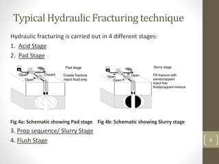
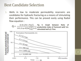
Hydraulic Fracturing
By
Shreyansh Shukla (67086)
[Guided By Prof S.J. NAIK] 1
Contents
1. Introduction to Hydraulic Fracturing
2. Typical Hydraulic Fracturing Technique
3. Best candidate selection
4. Fracture mechanics
5. Fracture Modelling
6. Fracture conductivity
7. Fracture treatment Optimization
8. Procedure for Hydraulic fracturing Treatment
9. Post Fracture well behavior
10. Case Study
11. Conclusions
12. References 2
Introduction
• The hydraulic fracturing process was developed in the
late 1940’s and has been successfully employed to
increase production in many wells which could not
otherwise have been produced economically.
• Basically it is a Well Stimulation technique in which Fluids
are injected in the wellbore to create fracture so that
near well bore permeability of a reservoir can be
increased.
• We pump this fluids at a rate higher than the rate at
which it can escape into the formation which increases
pressure in the wellbore thus causes breakage of the
rock inside formation.
Fig 1: Fracturing system and placement of proppants.
3
Proppants
• Proppant is the only material which is intended to remain in
the reservoir after a hydraulic fracturing treatment completion
and cleanup.
• Proppant placement creates a conductive pathway from the
reservoir to a wellbore
Fig 2: White frac sand Fig 3: Low density Ceramic
4
Need Of fracture
• As the life of well increases, the lower than expected gas or
oil can be seen which is mainly due to:
Factors affecting Reservoir deliverability:
Overestimate of reservoir pressure
Overestimate of reservoir permeability
Completion ineffectiveness
Formation damage.
Factors affecting Wellbore deliverability:
Restrictions in Wellbore due to paraffin, wax, scale, sand
production, etc.
• As a engineer it is important to identify and solve such
problems that may cause low production rates of wells,
decline of the desirable production fluid, etc.
5
Typical Hydraulic Fracturing technique
Hydraulic fracturing is carried out in 4 different stages:
1. Acid Stage
2. Pad Stage
Fig 4a: Schematic showing Pad stage Fig 4b: Schematic showing Slurry stage
3. Prop sequence/ Slurry Stage
4. Flush Stage 6
Best Candidate Selection
1. Wells in low to moderate permeability reservoirs are
candidates for hydraulic fracturing as a means of stimulating
their performance. This can be proved easily using Radial
flow equation :
Q =
𝑘∗ℎ∗(𝑃𝑒−𝑃𝑤𝑓)
141.2∗µ∗𝐵{ln
𝑟𝑒
𝑟𝑤
+𝑆}
Other factors that should be considered prior to conducting
hydraulic fracturing treatment are:
• The wellbore damage
• The formation flow capacity
• The existing reserves and/or depletion
• The economics
Fig 5: Graph between Ratio of
productivity Index of fractured well/ Un-
stimulated well v/s Time
7
Fracture Mechanics
• The mechanics of fracture initiation and extension, and the
resulting fracture geometry are related to the stress condition
near the borehole and in the surrounding rock, the properties
of the rock, the characteristics of the fracturing fluid, and the
manner in which the fluid is injected.
• It is well known that in the subsurface there are 3 principle
stresses oriented at right angles to each other [Fig 6].
• The magnitude and direction of the principle stresses are
important because they control the pressure required to
create and propagate a fracture, the shape and vertical extent
of the fracture, the direction of the fracture, and the stresses
trying to crush and/or embed the propping agent during
production.
• Fracture propagates in the perpendicular direction of
minimum stress (due to least resistance).
Fig 6: In-Situ stresses
8
 In-Situ stress calculation:
• Stress due to overburden pressure:
σ𝑣 =
ρ∗𝐻
144
• Effective stress:
σ'𝑣 = σ𝑣 − α ∗ 𝑃𝑝
• Effective horizontal stress:
σ′h=
ν
1−ν
σ′ 𝑣
Where, ν=Poisson’s ratio =
−Ɛ𝑦
Ɛ𝑥
=
−𝐿𝑎𝑡𝑒𝑟𝑎𝑙 𝑆𝑡𝑟𝑎𝑖𝑛
𝐿𝑜𝑛𝑔𝑖𝑡𝑢𝑑𝑖𝑛𝑎𝑙 𝑆𝑡𝑟𝑎𝑖𝑛
• Horizontal Stress:
σℎ = σ′ℎ + α ∗ 𝑃𝑝
• In-Situ stress or minimum principle stress:
σmin=
ν
1−ν
(σ1−α ∗ 𝑃𝑝)+ α ∗ 𝑃𝑝+ σext
Fig 7: Concept of effective stress between grains
9
Fracture Modelling
Types of Fracture Models:
1. 2-D Model
a) PKN Model: b) KGN Model:
2. 3-D Model
3. Psuedo-3-D Model
Fig 8: PKN Model Fig 9: KGN Model
10
Fracture Conductivity
• The Inflow Performance of a wellbore is controlled by a
dimensionless quantity:
Fcd =
𝐾𝑓∗𝑤
𝐾∗𝐿𝑓
=
𝑓𝑟𝑎𝑐𝑡𝑢𝑟𝑒 𝑝𝑒𝑟𝑚𝑒𝑎𝑏𝑖𝑙𝑖𝑡𝑦∗𝑤𝑖𝑑𝑡ℎ
𝑓𝑜𝑟𝑚𝑎𝑡𝑖𝑜𝑛 𝑝𝑒𝑟𝑚𝑒𝑎𝑏𝑖𝑙𝑖𝑡𝑦∗𝑓𝑟𝑎𝑐𝑡𝑢𝑟𝑒 𝑙𝑒𝑛𝑔𝑡ℎ
• The fracture conductivity can be increased by:
Increasing fracture width
By increasing proppant permeability and placement
Minimising the permeability damage to the proppant pack from
the fracturing fluid
Fig 9: Fracture Conductivity
11
Fracture treatment Optimization
Fracture treatment can be optimized by optimizing
1. Fracture size
2. Fracture containment
3. Fracture height Measurement
4. Fracture width
Fig 10: Importance of Fracture Size
Fig 11: Graph depicting
Importance of fracture
Optimization.
12
Procedurefor Hydraulic Fracturingtreatment
• Selection of Fracturing Fluid
• Selection of proppants
• Selection of fracturing
model.
• Selection of treatment size
• NPV analysis
Fig 12: The economic
conductivity pyramid showing 3
tiers proppant.
Fig 13: Proppant selection based
on closure pressure 13
Post Fracture well behavior
• Increase in Productivity Index
• Ultimate Recovery of fractured well
• Post fracture well test analyses.
Fig 14: Mcguire and Sikora graph
Fig 15a: production behavior in high
permeability well
Fig 15b: Production behavior in low
permeability well
14
Case Study
• Challenge:
Increase production and eliminate screenouts during the treatment of
mature oil fields in Egypt’s Western Desert. These complex fields produced
only marginal results with traditional hydraulic fracturing. Previous
fracturing designs and pumping techniques increased the risk of premature
screenouts.
• Solution:
Stimulated targeted wells with the HiWAY flow channel hydraulic fracturing
technique combined with RodPROP high aspect-ratio proppant.
• Results:
More than 20 wells have been successfully been treated in five different
fields for the operator, resulting in higher production, zero screenouts and
no proppant flowback. A comparison study of seven wells using the HiWAY
fracturing technique and conventionally treated wells showed an 89% initial
production increase and 199% long term production increase. 15
Conclusions
• Hydraulic Fracturing is a well stimulation technique used to
increase the Productivity Index of the un-stimulated well.
• Hydraulic fracturing designing and Best candidate selection plays
important role in making a fracturing job successful. Reservoir
characteristics, Rock characteristics, In-Situ stresses calculation are
calculated for Job designing.
• Optimization of Fracture Treatment is an important parameter for
making job economical and future prediction can be optimized
easily.
• Fracture width and fluid pressure drop acts as a important factor
in conductivity of fluid, maximum fluid pressure variation are due
to occurrence or removal of obstacles which affects the fluid
movement inside the fracture. These obstacles can prevent
forward movement of proppant inside fracture. 16
References
1. Ghalambor, A and Boyun Guo, “Petroleum Production Engineering”, Hydraulic
Fracturing, Elsevier Science & Technology Book, ISBN: 0750682701 (2007) (252-
265)
2. Joe Dunn Clegg, ”Production Operations Engineering- SPE Petroleum
Engineering Handbook”, Hydraulic Fracturing, Volume IV, (323-366).
3. M.J.Economides, A.D. Hill and C.Ehlig-Economides, ”Petroleum Production
System”, Parentice Hall, ISBN: 0-13-628683.
4. Heriot-Watt university, “Production Technology”,Hydraulic Fracturing, (47- 60).
5. Hilmar Von Schonfeldt, C.Fairhurst, Members AIME, ”Experiments on Hydraulic
Fracturing”, SPE 3033.
6. T. Allan and A. Roberts,”Production Operations” Volume 2 (4th edition), ISBN: 0-
93097218-X, Oil and Gas consultants Inc.
7. Gerald.H.Coulter, ”Hydraulic Fracturing-New Developments” JCPT 76-04-03,
OCT-DEC, 1976, Montreal (33-40)
8. J.Shlyapobersky,”Energy Analysis of Hydraulic Fracturing”, Shell Development
Company, 26th US Symposium on Rock Mechanics, Rapid City, 26-28 June1985.
9. Tingxue Jiang, XUgang Wang, Wenwen Shan, Yongli Wang, ”A New
Comprehensive Hydraulic Fracturing Technolgy To minimize Formation Damage
in Low Permeability Reservoirs”, SPE 82222, SPE European Formation Damage
Conference to be held in the Hague, The Netherlands, 13-14 May 2003.
10. http://www.slb.com/~/media/Files/stimulation/case_studies/hiway_egyptian_d
esert_cs.pdf
17
THANK YOU !!
18

Hydraulic fracturing

  • 1.
    Hydraulic Fracturing By Shreyansh Shukla(67086) [Guided By Prof S.J. NAIK] 1
  • 2.
    Contents 1. Introduction toHydraulic Fracturing 2. Typical Hydraulic Fracturing Technique 3. Best candidate selection 4. Fracture mechanics 5. Fracture Modelling 6. Fracture conductivity 7. Fracture treatment Optimization 8. Procedure for Hydraulic fracturing Treatment 9. Post Fracture well behavior 10. Case Study 11. Conclusions 12. References 2
  • 3.
    Introduction • The hydraulicfracturing process was developed in the late 1940’s and has been successfully employed to increase production in many wells which could not otherwise have been produced economically. • Basically it is a Well Stimulation technique in which Fluids are injected in the wellbore to create fracture so that near well bore permeability of a reservoir can be increased. • We pump this fluids at a rate higher than the rate at which it can escape into the formation which increases pressure in the wellbore thus causes breakage of the rock inside formation. Fig 1: Fracturing system and placement of proppants. 3
  • 4.
    Proppants • Proppant isthe only material which is intended to remain in the reservoir after a hydraulic fracturing treatment completion and cleanup. • Proppant placement creates a conductive pathway from the reservoir to a wellbore Fig 2: White frac sand Fig 3: Low density Ceramic 4
  • 5.
    Need Of fracture •As the life of well increases, the lower than expected gas or oil can be seen which is mainly due to: Factors affecting Reservoir deliverability: Overestimate of reservoir pressure Overestimate of reservoir permeability Completion ineffectiveness Formation damage. Factors affecting Wellbore deliverability: Restrictions in Wellbore due to paraffin, wax, scale, sand production, etc. • As a engineer it is important to identify and solve such problems that may cause low production rates of wells, decline of the desirable production fluid, etc. 5
  • 6.
    Typical Hydraulic Fracturingtechnique Hydraulic fracturing is carried out in 4 different stages: 1. Acid Stage 2. Pad Stage Fig 4a: Schematic showing Pad stage Fig 4b: Schematic showing Slurry stage 3. Prop sequence/ Slurry Stage 4. Flush Stage 6
  • 7.
    Best Candidate Selection 1.Wells in low to moderate permeability reservoirs are candidates for hydraulic fracturing as a means of stimulating their performance. This can be proved easily using Radial flow equation : Q = 𝑘∗ℎ∗(𝑃𝑒−𝑃𝑤𝑓) 141.2∗µ∗𝐵{ln 𝑟𝑒 𝑟𝑤 +𝑆} Other factors that should be considered prior to conducting hydraulic fracturing treatment are: • The wellbore damage • The formation flow capacity • The existing reserves and/or depletion • The economics Fig 5: Graph between Ratio of productivity Index of fractured well/ Un- stimulated well v/s Time 7
  • 8.
    Fracture Mechanics • Themechanics of fracture initiation and extension, and the resulting fracture geometry are related to the stress condition near the borehole and in the surrounding rock, the properties of the rock, the characteristics of the fracturing fluid, and the manner in which the fluid is injected. • It is well known that in the subsurface there are 3 principle stresses oriented at right angles to each other [Fig 6]. • The magnitude and direction of the principle stresses are important because they control the pressure required to create and propagate a fracture, the shape and vertical extent of the fracture, the direction of the fracture, and the stresses trying to crush and/or embed the propping agent during production. • Fracture propagates in the perpendicular direction of minimum stress (due to least resistance). Fig 6: In-Situ stresses 8
  • 9.
     In-Situ stresscalculation: • Stress due to overburden pressure: σ𝑣 = ρ∗𝐻 144 • Effective stress: σ'𝑣 = σ𝑣 − α ∗ 𝑃𝑝 • Effective horizontal stress: σ′h= ν 1−ν σ′ 𝑣 Where, ν=Poisson’s ratio = −Ɛ𝑦 Ɛ𝑥 = −𝐿𝑎𝑡𝑒𝑟𝑎𝑙 𝑆𝑡𝑟𝑎𝑖𝑛 𝐿𝑜𝑛𝑔𝑖𝑡𝑢𝑑𝑖𝑛𝑎𝑙 𝑆𝑡𝑟𝑎𝑖𝑛 • Horizontal Stress: σℎ = σ′ℎ + α ∗ 𝑃𝑝 • In-Situ stress or minimum principle stress: σmin= ν 1−ν (σ1−α ∗ 𝑃𝑝)+ α ∗ 𝑃𝑝+ σext Fig 7: Concept of effective stress between grains 9
  • 10.
    Fracture Modelling Types ofFracture Models: 1. 2-D Model a) PKN Model: b) KGN Model: 2. 3-D Model 3. Psuedo-3-D Model Fig 8: PKN Model Fig 9: KGN Model 10
  • 11.
    Fracture Conductivity • TheInflow Performance of a wellbore is controlled by a dimensionless quantity: Fcd = 𝐾𝑓∗𝑤 𝐾∗𝐿𝑓 = 𝑓𝑟𝑎𝑐𝑡𝑢𝑟𝑒 𝑝𝑒𝑟𝑚𝑒𝑎𝑏𝑖𝑙𝑖𝑡𝑦∗𝑤𝑖𝑑𝑡ℎ 𝑓𝑜𝑟𝑚𝑎𝑡𝑖𝑜𝑛 𝑝𝑒𝑟𝑚𝑒𝑎𝑏𝑖𝑙𝑖𝑡𝑦∗𝑓𝑟𝑎𝑐𝑡𝑢𝑟𝑒 𝑙𝑒𝑛𝑔𝑡ℎ • The fracture conductivity can be increased by: Increasing fracture width By increasing proppant permeability and placement Minimising the permeability damage to the proppant pack from the fracturing fluid Fig 9: Fracture Conductivity 11
  • 12.
    Fracture treatment Optimization Fracturetreatment can be optimized by optimizing 1. Fracture size 2. Fracture containment 3. Fracture height Measurement 4. Fracture width Fig 10: Importance of Fracture Size Fig 11: Graph depicting Importance of fracture Optimization. 12
  • 13.
    Procedurefor Hydraulic Fracturingtreatment •Selection of Fracturing Fluid • Selection of proppants • Selection of fracturing model. • Selection of treatment size • NPV analysis Fig 12: The economic conductivity pyramid showing 3 tiers proppant. Fig 13: Proppant selection based on closure pressure 13
  • 14.
    Post Fracture wellbehavior • Increase in Productivity Index • Ultimate Recovery of fractured well • Post fracture well test analyses. Fig 14: Mcguire and Sikora graph Fig 15a: production behavior in high permeability well Fig 15b: Production behavior in low permeability well 14
  • 15.
    Case Study • Challenge: Increaseproduction and eliminate screenouts during the treatment of mature oil fields in Egypt’s Western Desert. These complex fields produced only marginal results with traditional hydraulic fracturing. Previous fracturing designs and pumping techniques increased the risk of premature screenouts. • Solution: Stimulated targeted wells with the HiWAY flow channel hydraulic fracturing technique combined with RodPROP high aspect-ratio proppant. • Results: More than 20 wells have been successfully been treated in five different fields for the operator, resulting in higher production, zero screenouts and no proppant flowback. A comparison study of seven wells using the HiWAY fracturing technique and conventionally treated wells showed an 89% initial production increase and 199% long term production increase. 15
  • 16.
    Conclusions • Hydraulic Fracturingis a well stimulation technique used to increase the Productivity Index of the un-stimulated well. • Hydraulic fracturing designing and Best candidate selection plays important role in making a fracturing job successful. Reservoir characteristics, Rock characteristics, In-Situ stresses calculation are calculated for Job designing. • Optimization of Fracture Treatment is an important parameter for making job economical and future prediction can be optimized easily. • Fracture width and fluid pressure drop acts as a important factor in conductivity of fluid, maximum fluid pressure variation are due to occurrence or removal of obstacles which affects the fluid movement inside the fracture. These obstacles can prevent forward movement of proppant inside fracture. 16
  • 17.
    References 1. Ghalambor, Aand Boyun Guo, “Petroleum Production Engineering”, Hydraulic Fracturing, Elsevier Science & Technology Book, ISBN: 0750682701 (2007) (252- 265) 2. Joe Dunn Clegg, ”Production Operations Engineering- SPE Petroleum Engineering Handbook”, Hydraulic Fracturing, Volume IV, (323-366). 3. M.J.Economides, A.D. Hill and C.Ehlig-Economides, ”Petroleum Production System”, Parentice Hall, ISBN: 0-13-628683. 4. Heriot-Watt university, “Production Technology”,Hydraulic Fracturing, (47- 60). 5. Hilmar Von Schonfeldt, C.Fairhurst, Members AIME, ”Experiments on Hydraulic Fracturing”, SPE 3033. 6. T. Allan and A. Roberts,”Production Operations” Volume 2 (4th edition), ISBN: 0- 93097218-X, Oil and Gas consultants Inc. 7. Gerald.H.Coulter, ”Hydraulic Fracturing-New Developments” JCPT 76-04-03, OCT-DEC, 1976, Montreal (33-40) 8. J.Shlyapobersky,”Energy Analysis of Hydraulic Fracturing”, Shell Development Company, 26th US Symposium on Rock Mechanics, Rapid City, 26-28 June1985. 9. Tingxue Jiang, XUgang Wang, Wenwen Shan, Yongli Wang, ”A New Comprehensive Hydraulic Fracturing Technolgy To minimize Formation Damage in Low Permeability Reservoirs”, SPE 82222, SPE European Formation Damage Conference to be held in the Hague, The Netherlands, 13-14 May 2003. 10. http://www.slb.com/~/media/Files/stimulation/case_studies/hiway_egyptian_d esert_cs.pdf 17
  • 18.