Download to read offline
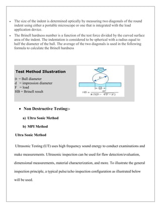

The document summarizes the manufacturing process of forged railway wheels at Durgapur Steel Plant in India. It describes the steel making process, wheel manufacturing, which involves casting ingots, heating billets, forging, rolling, machining and heat treatment. It also discusses testing methods like Brinell hardness testing and non-destructive testing to check for defects. Common wheel defects like wear, cracks and shelling are described along with factors that influence wheel life such as load, speed, track conditions and design.


