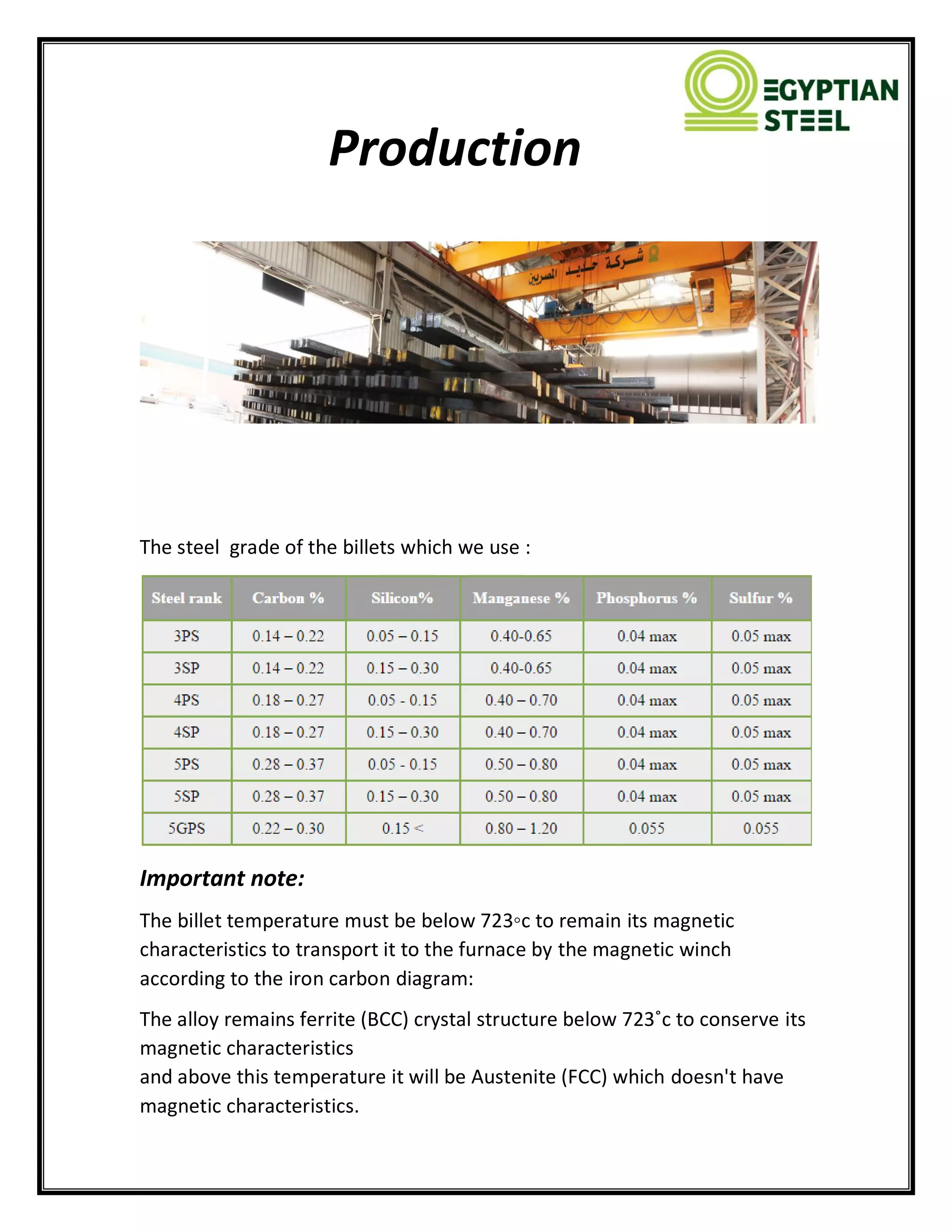
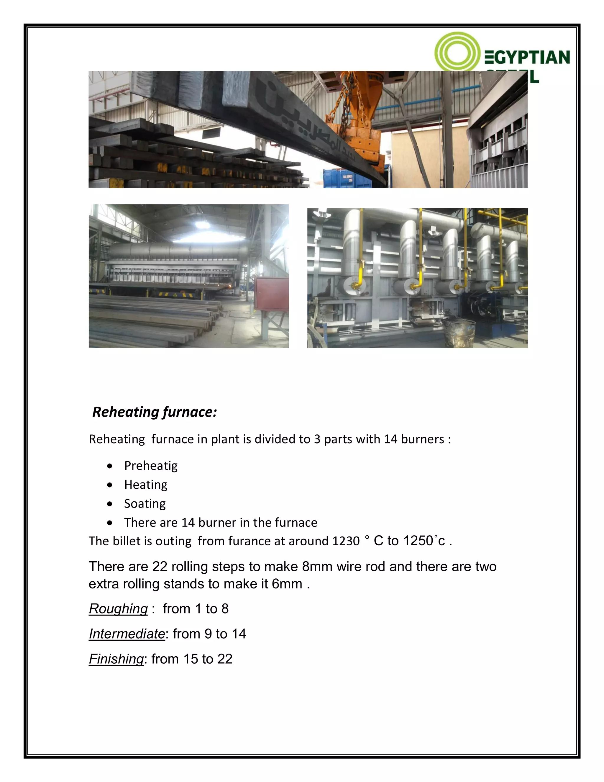
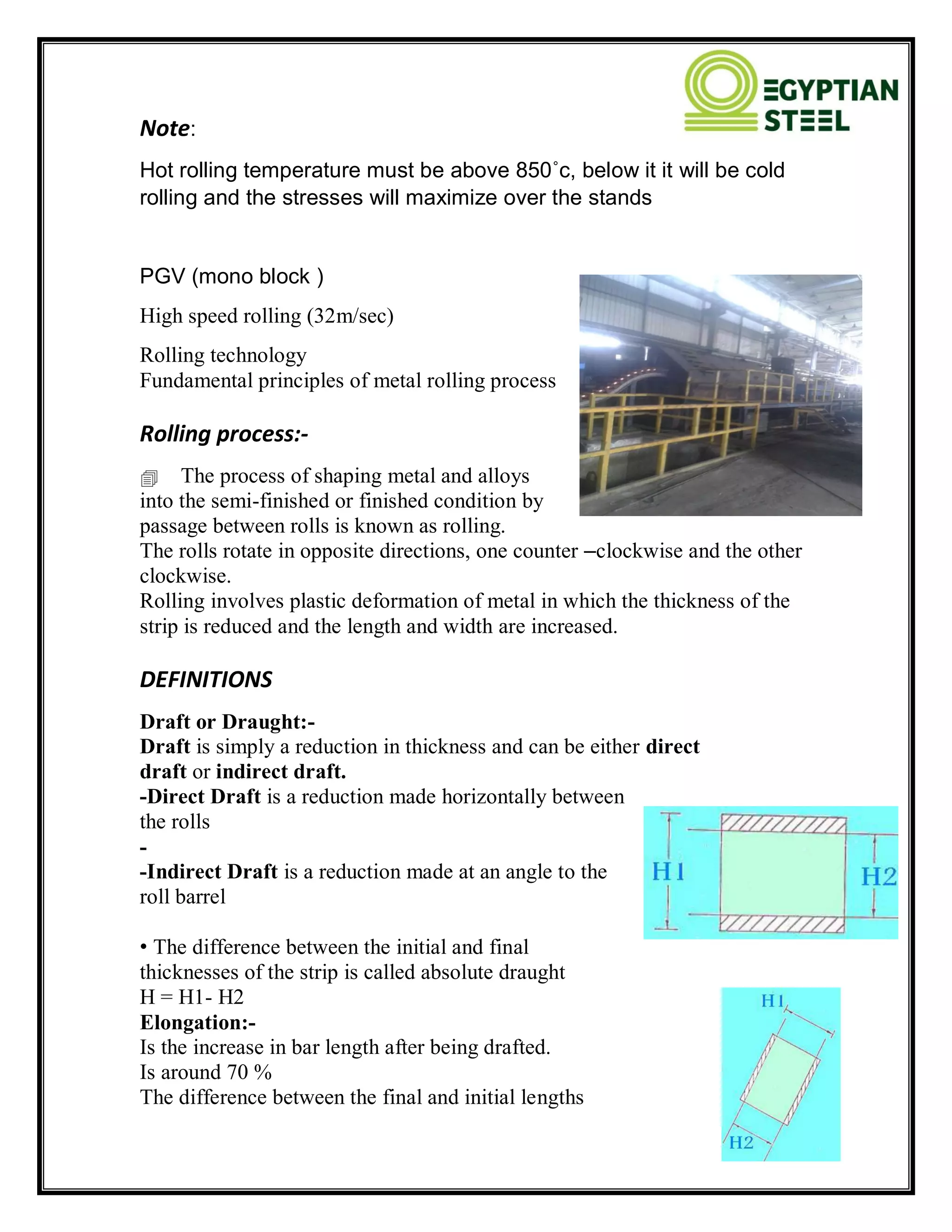
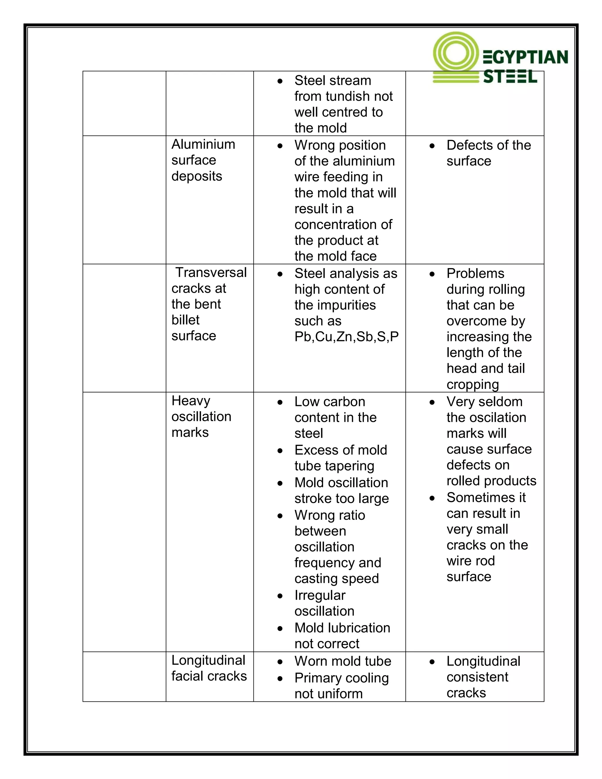
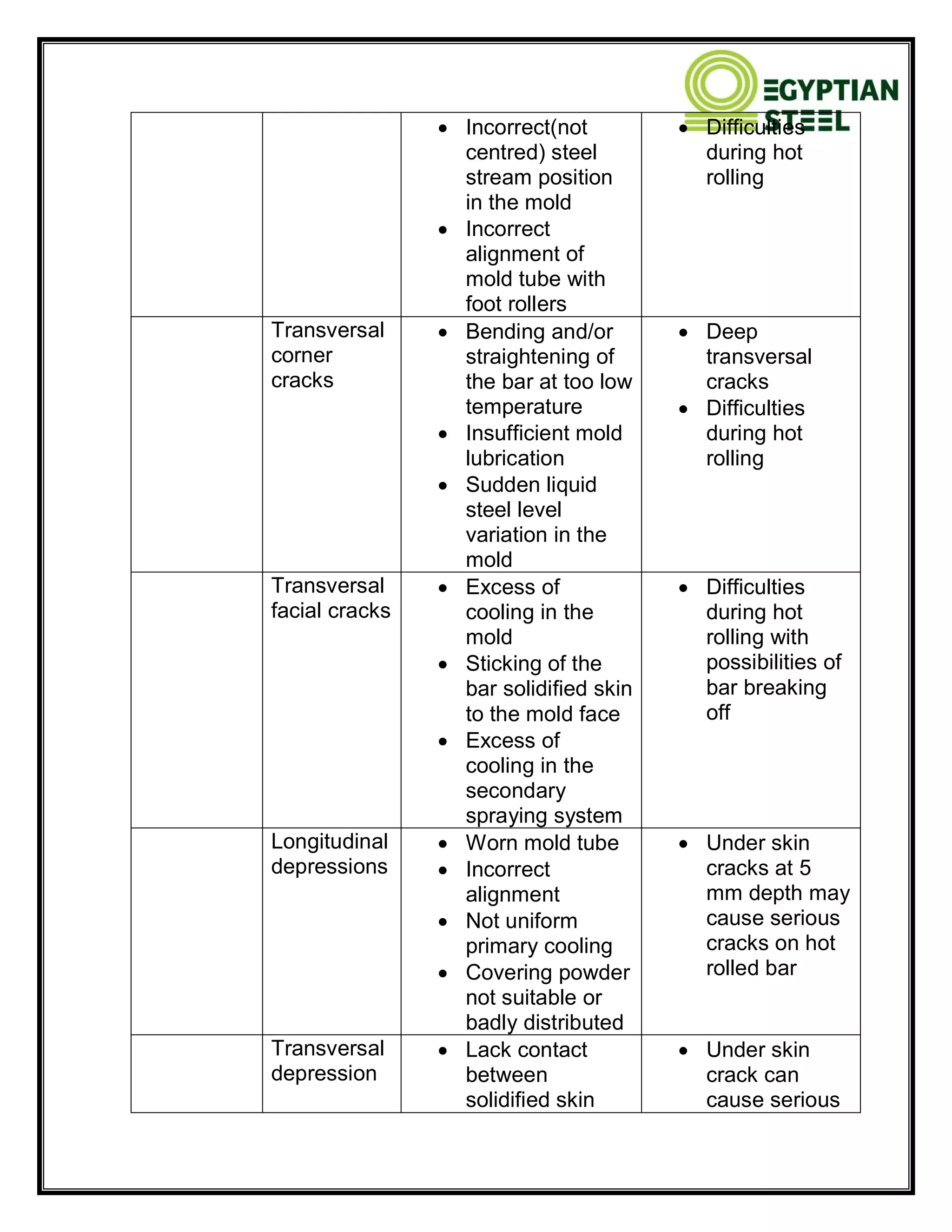
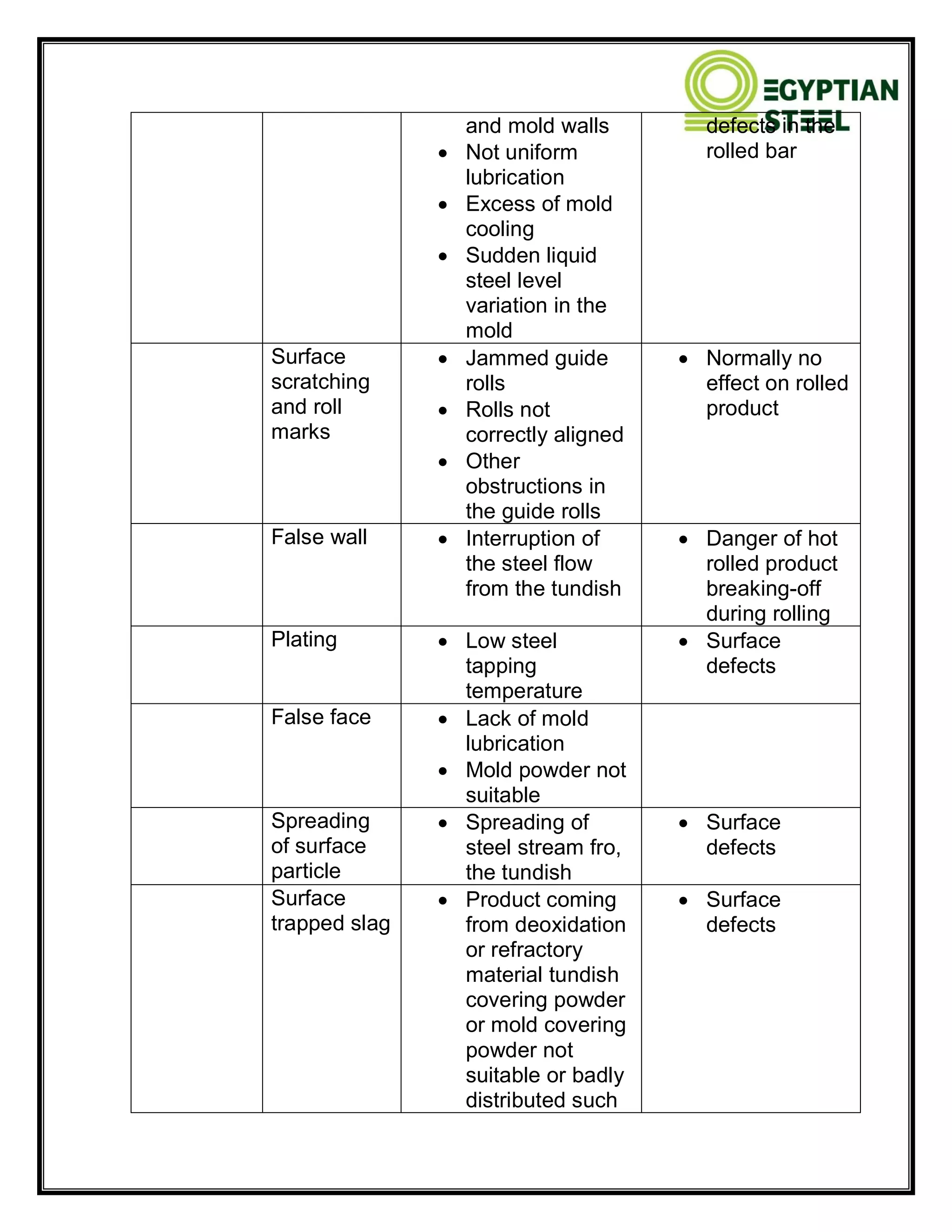
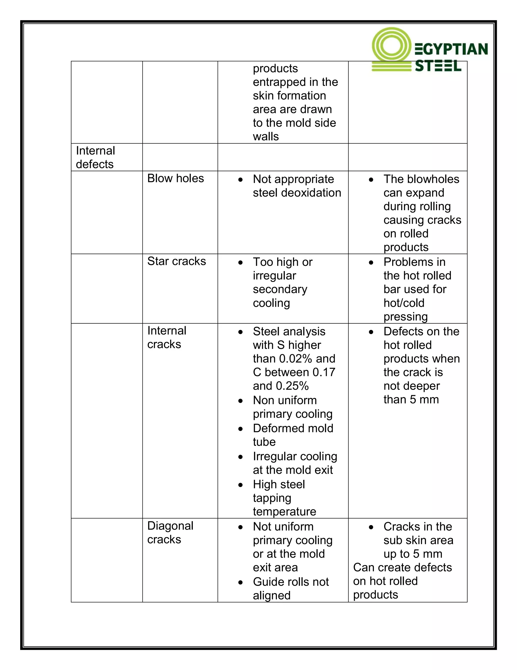
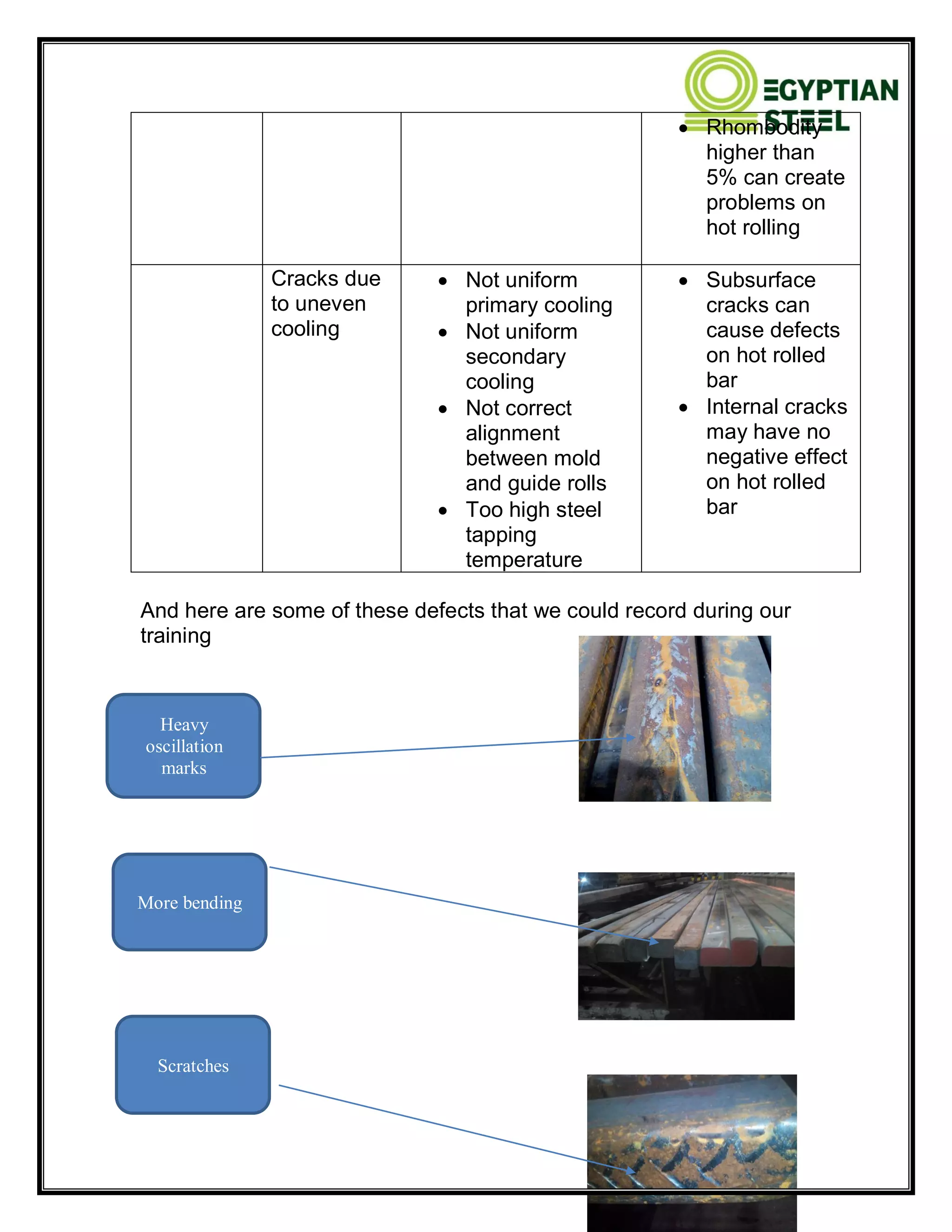
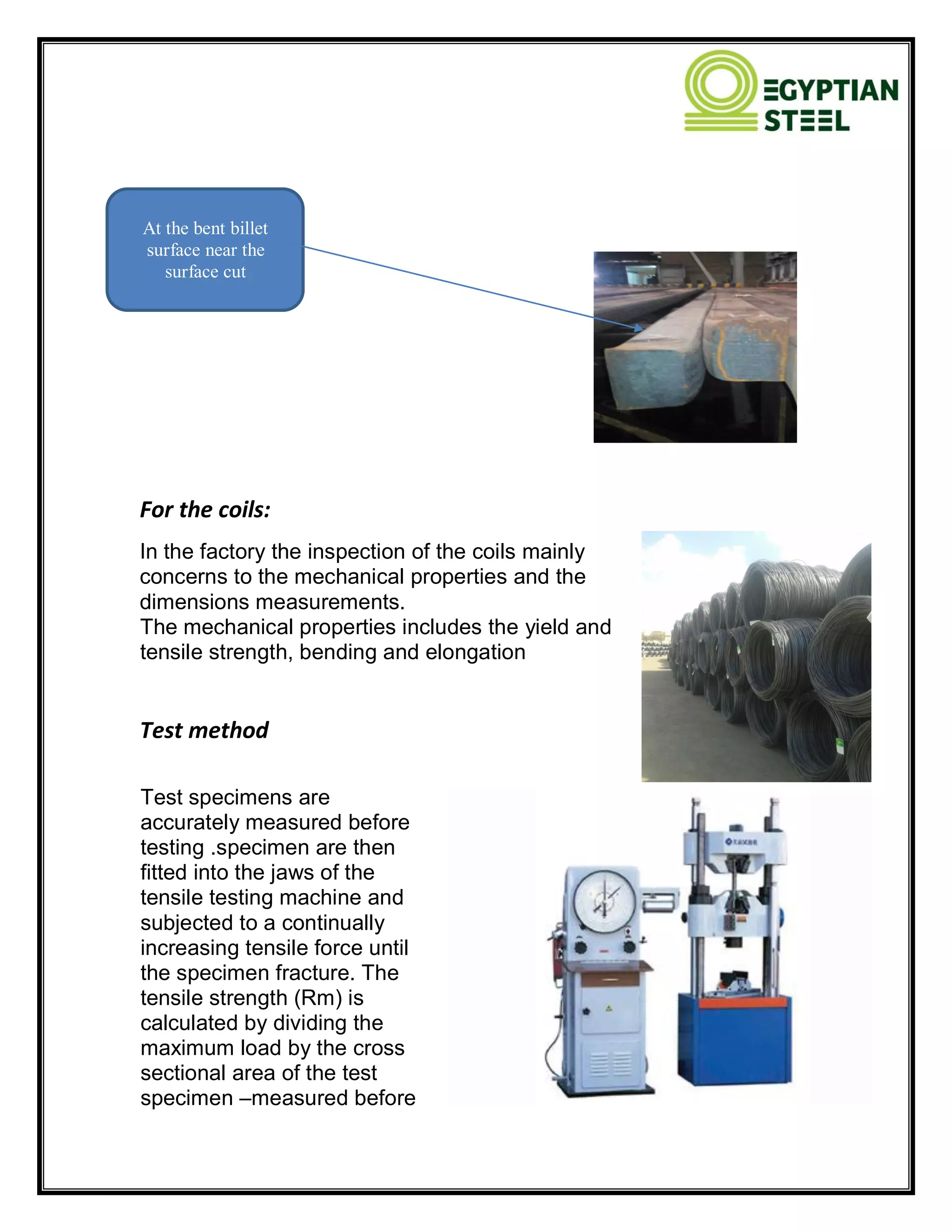
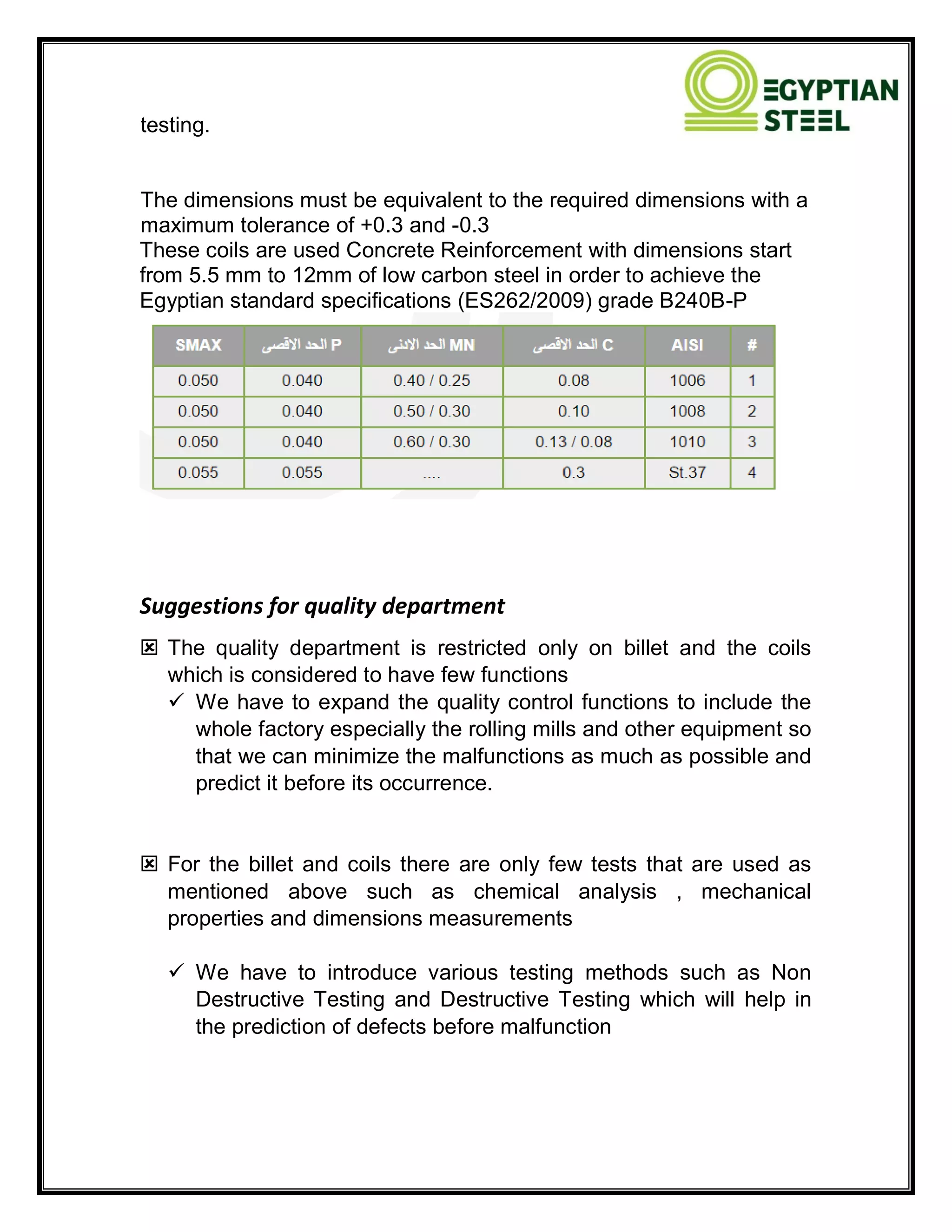
SlideShare a Scribd company logo
1 of 28
Download to read offline
Training Report
Production, Workshop & Quality control
By:
Amr Mansour
Hassan Ibrahim
Mohamed Sayed
Mahmoud Zakariya
Mahmoud AbdelRahman
2015
Alexandria
Egyptian steel
8/27/2015
Production
The steel grade of the billets which we use :
Important note:
The billet temperature must be below 723◦c to remain its magnetic
characteristics to transport it to the furnace by the magnetic winch
according to the iron carbon diagram:
The alloy remains ferrite (BCC) crystal structure below 723˚c to conserve its
magnetic characteristics
and above this temperature it will be Austenite (FCC) which doesn't have
magnetic characteristics.
Reheating furnace:
Reheating furnace in plant is divided to 3 parts with 14 burners :
 Preheatig
 Heating
 Soating
 There are 14 burner in the furnace
The billet is outing from furance at around 1230 ° C to 1250˚c .
There are 22 rolling steps to make 8mm wire rod and there are two
extra rolling stands to make it 6mm .
Roughing : from 1 to 8
Intermediate: from 9 to 14
Finishing: from 15 to 22
Note:
Hot rolling temperature must be above 850˚c, below it it will be cold
rolling and the stresses will maximize over the stands
PGV (mono block )
High speed rolling (32m/sec)
Rolling technology
Fundamental principles of metal rolling process
Rolling process:-
The process of shaping metal and alloys
into the semi-finished or finished condition by
passage between rolls is known as rolling.
The rolls rotate in opposite directions, one counter –clockwise and the other
clockwise.
Rolling involves plastic deformation of metal in which the thickness of the
strip is reduced and the length and width are increased.
DEFINITIONS
Draft or Draught:-
Draft is simply a reduction in thickness and can be either direct
draft or indirect draft.
-Direct Draft is a reduction made horizontally between
the rolls
-
-Indirect Draft is a reduction made at an angle to the
roll barrel
• The difference between the initial and final
thicknesses of the strip is called absolute draught
H = H1- H2
Elongation:-
Is the increase in bar length after being drafted.
Is around 70 %
The difference between the final and initial lengths
Is called the absolute elongation
L = L2 – L1
* The coefficient of elongation, i.e. the ratio of the length of the
metal after rolling to its initial length
Spread:-
Is the lateral or sideways movement of stock.
Is around 30 %
The difference between the final and initial widths
Is called the absolute spread
B = B2 – B1
Spread :- If we assume the same volume of material
enters and leaves the stand rolls, then the reduction in
thickness must be allied to an increase in width and length. The increase in
width is termed spread and it is generally around one third of the draft, but
the exact amount is determined by the following factors;
1- Temperature The hotter the material the less spread.
2- Chemical composition The higher the carbon the more spread.
3- Roll diameter The larger the roll the greater the spread.
4- Speed The higher the speed the less spread.
5- Pass shape some passes restrict spread while others
have zero control, and so flat rolls
(no pass groove) will have greater spread
The Angle of Bite and the Arc of Contact:
The Angle of Bite is the angle formed from the point
of contact
of bar entry to a perpendicular line through the
roll.Consider
30‫؛‬ as absolute maximum, and 22‫؛‬ as a general angle
for
smooth bite.
The Arc of Contact is the arc formed by the angle of
bite.
The larger the roll diameter the smaller the angle of bite
Speed control system:-
Modern continuous mills have a speed control system for
control and continuous adjustment of individual stand speeds.
1- tension control system:-
In the roughing and intermediate stands
2-loop control system :-
In the finishing stands, between each two stands
( the volume of steel going through each stand must be
the same to avoid tension or compression.)
inference important :-
A1 V1 = A2 V2 = An Vn = Constant
Constant = Area (mm2) x speed (m/sec)
Speed control system
1- tension control system :-
“push- pull “ conditions :-
For continuous rolling:-
volume flow must be balanced Speed and
/or areas
must be correctly designed and adjusted to
achieve this i.e.
Area 1 * speed 1 = area 2 * speed 2 = area
3 * speed 3
Compression between two stands :-
volume flow out of first stand is greater
than can be
accepted by second stand loop forms and
continues
to grow
Tension between two stands:-
Volume flow delivered by first stand is less
than is
required by the second stand bar is pulled between stands
and will neck down and pull apart if tension is
severe enough
2-loop control system :-
Important note:
Having said this, one very important point,
if adjustments are made to loopers or any
other equipment then the product must be
checked after each adjustment. So make
your adjustments slowly, one by one, and check after each adjustment.
Fail to do this and one day you will roll scrap.
Rolls Materials Types
There are three types of materials used to made mill rollers
1- iron rollers
2-steel rollers
3-carbides rollers
1- Indefinite chill rolls - or grain-iron, these are a low cost roll, versatile
and would be found in slabbing mills, plate mills,roughing stands,
intermediate stands and finishing stands of section mills
2- Double poured rolls - (sometimes called composite, although this leads
to misunderstanding with the carbide composites) are cast in two stages
with an alloyed iron barrel surface for hardness and an unalloyed core for
toughness, these rolls are to be found in strip mills and plate mills.
3- Definite chill rolls - an older type of roll with limited surface depth, still
in use in the shallower grooves of the finishing stands of rod and bar mills
4- Nodular iron rolls or spheroidal graphite – have great resistance to fire
cracking and distortion with good pass life, the general applications are
throughout the mills of rod, bar and small sections
Steel Rolls
Steel rolls have high strength and resistance to deflection, the types of steel
rolls available are:
1- Cast steel rolls - used where strength and toughness are the main
requirements. The surface of cast steel rolls is prone to break-up and local
distortion. Cast steel rolls may be found as back-up rolls in four high mills,
blooming and slabbing mills, large section mills and billet mills
2-Forged steel rolls - provide greater strength, hardness and wear resistance
than cast steel but are more expensive. Forged steel may be found in
blooming and slabbing mills, cold strip mills.
3- Steel base rolls - regarded as cast steel rolls although the carbon content
places them between a steel roll and an iron roll. They are manufactured in
the same way as a conventional cast steel roll but are usually alloyed. In
certain applications their characteristics are similar to Indefinite chill iron
rolls. Steel base rolls are to be found in large structural and section mills.
Carbide Rolls
Carbide rolls are in fact a compound of tungsten carbide with a binder or
cement normally of cobalt. This technology involves heating (sintering) and
compressing fine powdered particles until all porosity is eliminated and the
particles are fused together under extreme pressure. The final product is a
permanently compressed shape of superior mechanical composition, very
hard with a very high resistance to wear, (a carbide roll pass will outlive a
cast iron roll pass to the order often to one).
GUIDES
Guides are considered the very heart of a rolling
process. They are probably the most significant
factor in adjusting and control in the rolling
process. Every stand is consisting of entry guide,
mill roll and exit guide.
GUIDES TYPES
There are two main types of guide
1- Entry guides:-
The entry guide responsible to receive the bar that is coming from previous
and ensure enters to mill roll without any deviation
2- Exit guides:-
The exit guide delivery the bar to the next stand without any deviation too
and so on
1-Entry guide types
1- Static or friction entry guide:-
These types used to receive the bar section such as box or diamond or square
or round shape
2-Roller entry guide:-
These types used to receive the bar section
such as oval or former shape
And there are three types of roller entry guides
1- Single pair roller guide (SR) 2-double pair
roller guide (DR)
This type consist of this type consist of two
rollers four rollers
2-Exit guide types
1- Static or friction exit guide:-
The static guide shape depends on the metal stock and roll pass for stand.
There are three types:
1- Box exit static guide: such as used in roughing mill
Products
There will be two products in this plant after constructing the rebar line
soon:
1- Wire Rod:
Wire rod are small profiles including ordinary low carbon steel wire rods,
welding rod, blasting line with the rod, threaded rod straightening and
quality wire rod.
Common wire rod is mainly used for construction, wire drawing, packaging,
welding and manufacturing bolts, nuts and rivets.
2- Rebar:
The rebar is commonly used in reinforced concrete and reinforced
structures. It is usually formed from high carbon steel, and is given ridges
for better mechanical properties into the concrete.
It is widely used in various constructions, especially for large, heavy, light
thin and high-level construction. It's an important
material.
* The production of the factory is 300,000 ton/year
Workshop
1-the main function of workshop is to manufacture all required mechanical
components of spare parts of mill machine.
2- for periodic turning of corroded rings to re-use it again in rolling
operation.
3-to return rollers of roller guides.
4-fabrication works that required inside the plant.
Definition:
Computer Numerical Control (CNC) is one in
which the functions and motions of a
machine tool are controlled by means of a
prepared program containing coded
alphanumeric data. CNC can control the
motions of the work piece or tool, the input
parameters such as feed, depth of cut,
speed, and the functions such as turning
spindle on/off, turning coolant on/off.
remachined rings
Grinding CNC for tungsten carbide with electroplated diamond grinding wheel
general turning machinig
Directions
Mandrel to fix work piece
Holder and turning insert
The methods of manufacture in CNC
1-write G-code program for simple works
2- use cycles inside CNC control for more complex work piece
3-CAD-CAM software for complex geometry work piece
Applications:
The applications of CNC include both for machine tool as well as non-
machine tool areas. In the machine tool category, CNC is widely used
for lathe, drill press, milling machine, grinding unit, laser, sheet-metal
press working machine, tube bending machine etc. Highly automated
machine tools such as turning center and machining center which
change the cutting tools automatically under CNC control have been
developed. In the non-machine tool category, CNC applications
include welding machines (arc and resistance), coordinate
measuring machine, electronic assembly, tape laying and filament
winding machines for composites…. Etc.
Open Loop Control Systems :
The open-loop control means that there is no feedback and uses
stepping motors for driving the leadscrew . A stepping motor is a
device whose output shaft rotates through a fixed angle in response
to an input pulse.
Open loop control system
Closed-loop Control Systems:
Closed -loop NC systems are
appropriate when there is a force
resisting the movement of the tool/work piece .Milling and turning are
typical examples. In these systems. The DC servomotors and
feedback devices are used to ensure that the desired position is
achieved.
The feedback sensor used is an optical encoder. The encoder
consists of a light source, a photo detector, and a disk containing a
series of slots. The encoder is connected to the lead screw.
Closed-loop control system
PART PROGRAMMING FOR CNC:
we will describe how the part programmers execute manually the part
programs. A part programmer must have an extensive knowledge of
the machining processes and the capabilities of the machine tools
First, the machining parameters are determined. Second, the optimal
sequence of operations is evaluated
.Third, the tool path is calculated
.Fourth, and a program is written.
Sequence Number, N:
Consisting of typically three digits, its
purpose is to identify the specific
machining operation through the block
number particularly when testing a part
program.
Preparatory Function, G:
It prepares the MCU circuits to perform a specific operation. The G-
codes (some) are shown in the Table 1 implies incremental mode of
operation
*G codes used in CNC systems.
Table: 1 Preparatory commands (G-code)
G00 Point-to-point positioning
G01 Linear interpolation
G02 Clockwise circular interpolation
G03 Counter-clockwise circular interpolation
G04 Dwell
G05 Hold
G33 Thread cutting, constant lead
G40 Cancel tool nose radius compensation
G41 Tool nose radius compensation - left
G42 Tool nose radius compensation - right
G43 Cutter length compensation
G44 Cancel cutter length compensation
G70 Dimensions in inches
G71 Metric dimensions
G90 Absolute dimensions
G91 Incremental dimensions
G92 Datum offset
Dimension Words
1 . Distance dimension words, X,Y,Z
2 . Circular dimension words, I,J,K for distances to the arc center
3 . Angular dimensions, A,B.C
Spindle speed, S
Programmed in rev/min, it is expressed as RPM or by a three-digit
code number that is related to the RPM.
Miscellaneous Function, M
Consisting of two digits, this word relates to the movement of the
machine in terms of spindle on/off, coolant on/off etc shown in Table
2
Table: 2 Miscellaneous commands (M-code)
M00 Program stop
M01 Optional stop
M02 End of program
M03 Spindle start clockwise
M04 Spindle start counter-clockwise
M05 Spindle stop
M06 Tool change
M07 Mist coolant on
M08 Flood coolant on
M09 Coolant off
M10 Clamp
Mll Unclamp
M13 Spindle clockwise, coolant on
M14 Spindle counter-clockwise, coolant on
M30 End of tape rewinds.
Quality Control
Steel billet quality is one of the important factors affecting the quality
of rebar or coils that are produced in the Egyptian steel factory
because a small surface defect of a billet will be elongated during the
rolling and becomes an extensive product defect, requiring a
considerable cost for conditioning and fixing.
In the factory the function of the quality control department mainly
concerns in the billet as the initial source of the product and the coils
which are the final product of the factory.
For the Billet
The inspection of the billet has many
stages of inspection to insure that the
billet has the minimum defects with
which it can work and it's also inspected
by the chemical analysis test……
Here are some of the expected defects
that we may encounter in the billet and
their causes
Defect Possible causes Possible effects on
rolled product
Surface Minor
Pinholes
 Insufficient steel
deoxidation
 High content of
gas in the steel
(O,N,H)
 Excessive
amount of
casting oil
 Long and very
superficial
cracks on wire
rod
 Defects on
cold headed
product
Very small
pin holes
 Use of too much
lubrication oil in
the mold
 Very minor
influence on
hot rolled
product
Surface slag
>5mm
 Too much slag in
the steel
 Trapping of
products from
deoxidation
 Trapping of
products from
refractory
erosion
 Mn/Si ratio lower
than 2.5
 High alumina
content in the
covering powder
 In correct
distribution of
 Clearly visible
cracks and
fracture
 Overlapping
containing slag
 Steel sections
with outer
edges not
completely
formed
covering powder
 Sudden and
consistent steel
level in the mold
 Excess of Al wire
feeding in the
mold
Surface slag
<5mm
 Not much slag in
the steel
 Excess of
Aluminium wire
feeding in the
mold
 Mn/Si ratio very
low
 Secondary
oxidation
 Trapping of
covering powder
 Cracks of
various
dimensions
according to
slag particle
dimensions
Imperfect surface
Transverse
cracks at
the corner
 Deformed mold
tube
 Excess of mold
tapering
 Deposits on
external mold
surface tube
 Low hot
elongation of
steel (low Mn/Si
ratio)
 High steel
temperature
 High cooling of
the bar
concentrated in a
small area
 Irregular
oscillation
 Incorrect mold
 Large cracks
on the surface
 Rough surface
especially on
wire rod
 Possibility
breaking-off of
the bar during
hot rolling
lubrication
Longitudinal
cracks
 Worn mold tube
 Too large corner
radius in the
mold tube
 Excess of mold
cooling or
uneven mold
cooling pattern
 Too high steel
tapping
temperature
 Misalignment of
foot rollers or
guide and sprays
 Long and deep
surface cracks
Folding and
cold welding
 Worn or
deformed mold
tube
 Mold lubrication
not suitable
 Excess of slag in
the steel
 Low steel
tapping
temperature
 Low casting
speed
 Cracks and
laps
 Danger of
breaking-off of
the bar during
hot rolling
Healed
breakouts
 Worn or
deformed mold
tube
 Defective mold
lubrication
 Uneven mold
cooling
 Excess of slag in
the steel
 High steel
tapping
temperature
 Consistent
surface
defects
 Steel stream
from tundish not
well centred to
the mold
Aluminium
surface
deposits
 Wrong position
of the aluminium
wire feeding in
the mold that will
result in a
concentration of
the product at
the mold face
 Defects of the
surface
Transversal
cracks at
the bent
billet
surface
 Steel analysis as
high content of
the impurities
such as
Pb,Cu,Zn,Sb,S,P
 Problems
during rolling
that can be
overcome by
increasing the
length of the
head and tail
cropping
Heavy
oscillation
marks
 Low carbon
content in the
steel
 Excess of mold
tube tapering
 Mold oscillation
stroke too large
 Wrong ratio
between
oscillation
frequency and
casting speed
 Irregular
oscillation
 Mold lubrication
not correct
 Very seldom
the oscilation
marks will
cause surface
defects on
rolled products
 Sometimes it
can result in
very small
cracks on the
wire rod
surface
Longitudinal
facial cracks
 Worn mold tube
 Primary cooling
not uniform
 Longitudinal
consistent
cracks
 Incorrect(not
centred) steel
stream position
in the mold
 Incorrect
alignment of
mold tube with
foot rollers
 Difficulties
during hot
rolling
Transversal
corner
cracks
 Bending and/or
straightening of
the bar at too low
temperature
 Insufficient mold
lubrication
 Sudden liquid
steel level
variation in the
mold
 Deep
transversal
cracks
 Difficulties
during hot
rolling
Transversal
facial cracks
 Excess of
cooling in the
mold
 Sticking of the
bar solidified skin
to the mold face
 Excess of
cooling in the
secondary
spraying system
 Difficulties
during hot
rolling with
possibilities of
bar breaking
off
Longitudinal
depressions
 Worn mold tube
 Incorrect
alignment
 Not uniform
primary cooling
 Covering powder
not suitable or
badly distributed
 Under skin
cracks at 5
mm depth may
cause serious
cracks on hot
rolled bar
Transversal
depression
 Lack contact
between
solidified skin
 Under skin
crack can
cause serious
and mold walls
 Not uniform
lubrication
 Excess of mold
cooling
 Sudden liquid
steel level
variation in the
mold
defects in the
rolled bar
Surface
scratching
and roll
marks
 Jammed guide
rolls
 Rolls not
correctly aligned
 Other
obstructions in
the guide rolls
 Normally no
effect on rolled
product
False wall  Interruption of
the steel flow
from the tundish
 Danger of hot
rolled product
breaking-off
during rolling
Plating  Low steel
tapping
temperature
 Surface
defects
False face  Lack of mold
lubrication
 Mold powder not
suitable
Spreading
of surface
particle
 Spreading of
steel stream fro,
the tundish
 Surface
defects
Surface
trapped slag
 Product coming
from deoxidation
or refractory
material tundish
covering powder
or mold covering
powder not
suitable or badly
distributed such
 Surface
defects
products
entrapped in the
skin formation
area are drawn
to the mold side
walls
Internal
defects
Blow holes  Not appropriate
steel deoxidation
 The blowholes
can expand
during rolling
causing cracks
on rolled
products
Star cracks  Too high or
irregular
secondary
cooling
 Problems in
the hot rolled
bar used for
hot/cold
pressing
Internal
cracks
 Steel analysis
with S higher
than 0.02% and
C between 0.17
and 0.25%
 Non uniform
primary cooling
 Deformed mold
tube
 Irregular cooling
at the mold exit
 High steel
tapping
temperature
 Defects on the
hot rolled
products when
the crack is
not deeper
than 5 mm
Diagonal
cracks
 Not uniform
primary cooling
or at the mold
exit area
 Guide rolls not
aligned
 Cracks in the
sub skin area
up to 5 mm
Can create defects
on hot rolled
products
 Rhombodity
higher than
5% can create
problems on
hot rolling
Cracks due
to uneven
cooling
 Not uniform
primary cooling
 Not uniform
secondary
cooling
 Not correct
alignment
between mold
and guide rolls
 Too high steel
tapping
temperature
 Subsurface
cracks can
cause defects
on hot rolled
bar
 Internal cracks
may have no
negative effect
on hot rolled
bar
And here are some of these defects that we could record during our
training
For the coils
Heavy
oscillation
marks
More bending
Scratches
For the coils:
In the factory the inspection of the coils mainly
concerns to the mechanical properties and the
dimensions measurements.
The mechanical properties includes the yield and
tensile strength, bending and elongation
Test method
Test specimens are
accurately measured before
testing .specimen are then
fitted into the jaws of the
tensile testing machine and
subjected to a continually
increasing tensile force until
the specimen fracture. The
tensile strength (Rm) is
calculated by dividing the
maximum load by the cross
sectional area of the test
specimen –measured before
At the bent billet
surface near the
surface cut
testing.
The dimensions must be equivalent to the required dimensions with a
maximum tolerance of +0.3 and -0.3
These coils are used Concrete Reinforcement with dimensions start
from 5.5 mm to 12mm of low carbon steel in order to achieve the
Egyptian standard specifications (ES262/2009) grade B240B-P
Suggestions for quality department
 The quality department is restricted only on billet and the coils
which is considered to have few functions
 We have to expand the quality control functions to include the
whole factory especially the rolling mills and other equipment so
that we can minimize the malfunctions as much as possible and
predict it before its occurrence.
 For the billet and coils there are only few tests that are used as
mentioned above such as chemical analysis , mechanical
properties and dimensions measurements
 We have to introduce various testing methods such as Non
Destructive Testing and Destructive Testing which will help in
the prediction of defects before malfunction
At the end of our training ... it was an honor
for us to spend a month in such a promising
factory with the help of the engineers who
dedicate their time and effort for our benefit
hoping to develop this factory which will remain
in our memories and minds as the place where
we gained great experience and skills.
…..

More Related Content

What's hot

Unit iv SHEET METAL PROCESSES
Unit   iv SHEET METAL PROCESSES Unit   iv SHEET METAL PROCESSES
Unit iv SHEET METAL PROCESSES SelvamV17
 
Assignment on forging
Assignment on  forgingAssignment on  forging
Assignment on forgingtareq hasan
 
Unit iii METAL FORMING PROCESSES
Unit   iii METAL FORMING PROCESSESUnit   iii METAL FORMING PROCESSES
Unit iii METAL FORMING PROCESSESSelvamV17
 
METAL FORMING PROCESSES
METAL FORMING PROCESSESMETAL FORMING PROCESSES
METAL FORMING PROCESSESRaja P
 
Mp 1-unit - iii - metal forming processes
Mp 1-unit - iii - metal forming processesMp 1-unit - iii - metal forming processes
Mp 1-unit - iii - metal forming processeskarthi keyan
 
Introduction to Forging
Introduction to ForgingIntroduction to Forging
Introduction to ForgingVibhas Purushu
 
China mill rolls, roll rings, stainless steel roller mould suppliers, manufac...
China mill rolls, roll rings, stainless steel roller mould suppliers, manufac...China mill rolls, roll rings, stainless steel roller mould suppliers, manufac...
China mill rolls, roll rings, stainless steel roller mould suppliers, manufac...NeelHope
 
2. Rolling process
2. Rolling process2. Rolling process
2. Rolling processPartap Samra
 
Fabrication of steel plate girder
Fabrication of steel plate girderFabrication of steel plate girder
Fabrication of steel plate girderRajesh Maurya
 
Rolling mills
Rolling millsRolling mills
Rolling millsMaharmts
 
Engineering Workshop
Engineering WorkshopEngineering Workshop
Engineering WorkshopKarthikeyan I
 
Rod, wire and tube drawing
Rod, wire and tube drawingRod, wire and tube drawing
Rod, wire and tube drawingNaman Dave
 
Rolling of Metals
Rolling of MetalsRolling of Metals
Rolling of MetalsBilal
 

What's hot (19)

AGC
AGCAGC
AGC
 
Met 402 mod_3
Met 402 mod_3Met 402 mod_3
Met 402 mod_3
 
Unit iv SHEET METAL PROCESSES
Unit   iv SHEET METAL PROCESSES Unit   iv SHEET METAL PROCESSES
Unit iv SHEET METAL PROCESSES
 
Assignment on forging
Assignment on  forgingAssignment on  forging
Assignment on forging
 
DRAWING PROCESS AND DRAWING MACHINES
DRAWING PROCESS AND DRAWING MACHINESDRAWING PROCESS AND DRAWING MACHINES
DRAWING PROCESS AND DRAWING MACHINES
 
Unit iii METAL FORMING PROCESSES
Unit   iii METAL FORMING PROCESSESUnit   iii METAL FORMING PROCESSES
Unit iii METAL FORMING PROCESSES
 
METAL FORMING PROCESSES
METAL FORMING PROCESSESMETAL FORMING PROCESSES
METAL FORMING PROCESSES
 
Mp 1-unit - iii - metal forming processes
Mp 1-unit - iii - metal forming processesMp 1-unit - iii - metal forming processes
Mp 1-unit - iii - metal forming processes
 
Introduction to Forging
Introduction to ForgingIntroduction to Forging
Introduction to Forging
 
Forging
ForgingForging
Forging
 
China mill rolls, roll rings, stainless steel roller mould suppliers, manufac...
China mill rolls, roll rings, stainless steel roller mould suppliers, manufac...China mill rolls, roll rings, stainless steel roller mould suppliers, manufac...
China mill rolls, roll rings, stainless steel roller mould suppliers, manufac...
 
Forging and-press-working-8248098
Forging and-press-working-8248098Forging and-press-working-8248098
Forging and-press-working-8248098
 
2. Rolling process
2. Rolling process2. Rolling process
2. Rolling process
 
Fabrication of steel plate girder
Fabrication of steel plate girderFabrication of steel plate girder
Fabrication of steel plate girder
 
PRESS FORGING
PRESS FORGINGPRESS FORGING
PRESS FORGING
 
Rolling mills
Rolling millsRolling mills
Rolling mills
 
Engineering Workshop
Engineering WorkshopEngineering Workshop
Engineering Workshop
 
Rod, wire and tube drawing
Rod, wire and tube drawingRod, wire and tube drawing
Rod, wire and tube drawing
 
Rolling of Metals
Rolling of MetalsRolling of Metals
Rolling of Metals
 

Similar to Training Report: Steel Production Process and Quality Control

Manufacturing Process -.pptx
Manufacturing Process -.pptxManufacturing Process -.pptx
Manufacturing Process -.pptxNIHALMENARIA
 
Rolling slides
Rolling slidesRolling slides
Rolling slidesZiad Salem
 
Production chapter 5 2016
Production chapter 5 2016Production chapter 5 2016
Production chapter 5 2016Ahmad Afia
 
Rolling process presentation
Rolling process presentationRolling process presentation
Rolling process presentationmanojkumarjain20
 
PT R19 - UNIT-5.pdf
PT R19 - UNIT-5.pdfPT R19 - UNIT-5.pdf
PT R19 - UNIT-5.pdfCMohan4
 
WORKSHOP TECHNOLOGY PPT.pptx
WORKSHOP TECHNOLOGY PPT.pptxWORKSHOP TECHNOLOGY PPT.pptx
WORKSHOP TECHNOLOGY PPT.pptxmayank bhatt
 
AMP combined pdf unit 1- 3 by(badebhau4@gmail.com)
AMP combined pdf unit 1- 3 by(badebhau4@gmail.com)AMP combined pdf unit 1- 3 by(badebhau4@gmail.com)
AMP combined pdf unit 1- 3 by(badebhau4@gmail.com)Er. Bade Bhausaheb
 
AMP . Unit .1 Metal forming (badebhau4@gmail.com)
AMP . Unit .1 Metal forming (badebhau4@gmail.com)AMP . Unit .1 Metal forming (badebhau4@gmail.com)
AMP . Unit .1 Metal forming (badebhau4@gmail.com)Er. Bade Bhausaheb
 
IIIE SECTION A MANUFACTURING TECHNOLOGY NOTES 8.die castings
IIIE SECTION A MANUFACTURING TECHNOLOGY NOTES 8.die castingsIIIE SECTION A MANUFACTURING TECHNOLOGY NOTES 8.die castings
IIIE SECTION A MANUFACTURING TECHNOLOGY NOTES 8.die castingsBhaskar Nagarajan
 
chapter 2 Bulk Deformation Processes in Metal Forming.ppt
chapter 2  Bulk Deformation Processes in Metal Forming.pptchapter 2  Bulk Deformation Processes in Metal Forming.ppt
chapter 2 Bulk Deformation Processes in Metal Forming.pptBarsena
 
Bulk deformation Processes in Metal Working
Bulk deformation Processes in Metal WorkingBulk deformation Processes in Metal Working
Bulk deformation Processes in Metal WorkingMuhammadUsman1795
 
Wringer_roll_Position_control_final(edited)
Wringer_roll_Position_control_final(edited)Wringer_roll_Position_control_final(edited)
Wringer_roll_Position_control_final(edited)SHASHANK KUMAR
 
Metal Rolling Process
Metal Rolling ProcessMetal Rolling Process
Metal Rolling ProcessPandya Kartik
 
Steel building construction
Steel building constructionSteel building construction
Steel building constructionshreyas mishra
 

Similar to Training Report: Steel Production Process and Quality Control (20)

Manufacturing Process -.pptx
Manufacturing Process -.pptxManufacturing Process -.pptx
Manufacturing Process -.pptx
 
Rolling Process
Rolling ProcessRolling Process
Rolling Process
 
Rolling slides
Rolling slidesRolling slides
Rolling slides
 
Rolling.pdf
Rolling.pdfRolling.pdf
Rolling.pdf
 
Production chapter 5 2016
Production chapter 5 2016Production chapter 5 2016
Production chapter 5 2016
 
Rolling process presentation
Rolling process presentationRolling process presentation
Rolling process presentation
 
STEEL.pptx
STEEL.pptxSTEEL.pptx
STEEL.pptx
 
PT R19 - UNIT-5.pdf
PT R19 - UNIT-5.pdfPT R19 - UNIT-5.pdf
PT R19 - UNIT-5.pdf
 
WORKSHOP TECHNOLOGY PPT.pptx
WORKSHOP TECHNOLOGY PPT.pptxWORKSHOP TECHNOLOGY PPT.pptx
WORKSHOP TECHNOLOGY PPT.pptx
 
Truck spring leaves
Truck spring leavesTruck spring leaves
Truck spring leaves
 
AMP combined pdf unit 1- 3 by(badebhau4@gmail.com)
AMP combined pdf unit 1- 3 by(badebhau4@gmail.com)AMP combined pdf unit 1- 3 by(badebhau4@gmail.com)
AMP combined pdf unit 1- 3 by(badebhau4@gmail.com)
 
AMP . Unit .1 Metal forming (badebhau4@gmail.com)
AMP . Unit .1 Metal forming (badebhau4@gmail.com)AMP . Unit .1 Metal forming (badebhau4@gmail.com)
AMP . Unit .1 Metal forming (badebhau4@gmail.com)
 
IIIE SECTION A MANUFACTURING TECHNOLOGY NOTES 8.die castings
IIIE SECTION A MANUFACTURING TECHNOLOGY NOTES 8.die castingsIIIE SECTION A MANUFACTURING TECHNOLOGY NOTES 8.die castings
IIIE SECTION A MANUFACTURING TECHNOLOGY NOTES 8.die castings
 
chapter 2 Bulk Deformation Processes in Metal Forming.ppt
chapter 2  Bulk Deformation Processes in Metal Forming.pptchapter 2  Bulk Deformation Processes in Metal Forming.ppt
chapter 2 Bulk Deformation Processes in Metal Forming.ppt
 
Bulk deformation Processes in Metal Working
Bulk deformation Processes in Metal WorkingBulk deformation Processes in Metal Working
Bulk deformation Processes in Metal Working
 
Wringer_roll_Position_control_final(edited)
Wringer_roll_Position_control_final(edited)Wringer_roll_Position_control_final(edited)
Wringer_roll_Position_control_final(edited)
 
Metal Rolling Process
Metal Rolling ProcessMetal Rolling Process
Metal Rolling Process
 
Steel building construction
Steel building constructionSteel building construction
Steel building construction
 
Continuous casting of steel
Continuous casting of steel Continuous casting of steel
Continuous casting of steel
 
Final pdf report
Final pdf reportFinal pdf report
Final pdf report
 

Training Report: Steel Production Process and Quality Control

  • 1. Training Report Production, Workshop & Quality control By: Amr Mansour Hassan Ibrahim Mohamed Sayed Mahmoud Zakariya Mahmoud AbdelRahman 2015 Alexandria Egyptian steel 8/27/2015
  • 2. Production The steel grade of the billets which we use : Important note: The billet temperature must be below 723◦c to remain its magnetic characteristics to transport it to the furnace by the magnetic winch according to the iron carbon diagram: The alloy remains ferrite (BCC) crystal structure below 723˚c to conserve its magnetic characteristics and above this temperature it will be Austenite (FCC) which doesn't have magnetic characteristics.
  • 3. Reheating furnace: Reheating furnace in plant is divided to 3 parts with 14 burners :  Preheatig  Heating  Soating  There are 14 burner in the furnace The billet is outing from furance at around 1230 ° C to 1250˚c . There are 22 rolling steps to make 8mm wire rod and there are two extra rolling stands to make it 6mm . Roughing : from 1 to 8 Intermediate: from 9 to 14 Finishing: from 15 to 22
  • 4. Note: Hot rolling temperature must be above 850˚c, below it it will be cold rolling and the stresses will maximize over the stands PGV (mono block ) High speed rolling (32m/sec) Rolling technology Fundamental principles of metal rolling process Rolling process:- The process of shaping metal and alloys into the semi-finished or finished condition by passage between rolls is known as rolling. The rolls rotate in opposite directions, one counter –clockwise and the other clockwise. Rolling involves plastic deformation of metal in which the thickness of the strip is reduced and the length and width are increased. DEFINITIONS Draft or Draught:- Draft is simply a reduction in thickness and can be either direct draft or indirect draft. -Direct Draft is a reduction made horizontally between the rolls - -Indirect Draft is a reduction made at an angle to the roll barrel • The difference between the initial and final thicknesses of the strip is called absolute draught H = H1- H2 Elongation:- Is the increase in bar length after being drafted. Is around 70 % The difference between the final and initial lengths
  • 5. Is called the absolute elongation L = L2 – L1 * The coefficient of elongation, i.e. the ratio of the length of the metal after rolling to its initial length Spread:- Is the lateral or sideways movement of stock. Is around 30 % The difference between the final and initial widths Is called the absolute spread B = B2 – B1 Spread :- If we assume the same volume of material enters and leaves the stand rolls, then the reduction in thickness must be allied to an increase in width and length. The increase in width is termed spread and it is generally around one third of the draft, but the exact amount is determined by the following factors; 1- Temperature The hotter the material the less spread. 2- Chemical composition The higher the carbon the more spread. 3- Roll diameter The larger the roll the greater the spread. 4- Speed The higher the speed the less spread. 5- Pass shape some passes restrict spread while others have zero control, and so flat rolls (no pass groove) will have greater spread The Angle of Bite and the Arc of Contact: The Angle of Bite is the angle formed from the point of contact of bar entry to a perpendicular line through the roll.Consider 30‫؛‬ as absolute maximum, and 22‫؛‬ as a general angle for smooth bite. The Arc of Contact is the arc formed by the angle of bite. The larger the roll diameter the smaller the angle of bite Speed control system:- Modern continuous mills have a speed control system for control and continuous adjustment of individual stand speeds.
  • 6. 1- tension control system:- In the roughing and intermediate stands 2-loop control system :- In the finishing stands, between each two stands ( the volume of steel going through each stand must be the same to avoid tension or compression.) inference important :- A1 V1 = A2 V2 = An Vn = Constant Constant = Area (mm2) x speed (m/sec) Speed control system 1- tension control system :- “push- pull “ conditions :- For continuous rolling:- volume flow must be balanced Speed and /or areas must be correctly designed and adjusted to achieve this i.e. Area 1 * speed 1 = area 2 * speed 2 = area 3 * speed 3 Compression between two stands :- volume flow out of first stand is greater than can be accepted by second stand loop forms and continues to grow Tension between two stands:- Volume flow delivered by first stand is less than is
  • 7. required by the second stand bar is pulled between stands and will neck down and pull apart if tension is severe enough 2-loop control system :- Important note: Having said this, one very important point, if adjustments are made to loopers or any other equipment then the product must be checked after each adjustment. So make your adjustments slowly, one by one, and check after each adjustment. Fail to do this and one day you will roll scrap. Rolls Materials Types There are three types of materials used to made mill rollers 1- iron rollers 2-steel rollers 3-carbides rollers 1- Indefinite chill rolls - or grain-iron, these are a low cost roll, versatile and would be found in slabbing mills, plate mills,roughing stands, intermediate stands and finishing stands of section mills 2- Double poured rolls - (sometimes called composite, although this leads to misunderstanding with the carbide composites) are cast in two stages with an alloyed iron barrel surface for hardness and an unalloyed core for toughness, these rolls are to be found in strip mills and plate mills. 3- Definite chill rolls - an older type of roll with limited surface depth, still in use in the shallower grooves of the finishing stands of rod and bar mills 4- Nodular iron rolls or spheroidal graphite – have great resistance to fire cracking and distortion with good pass life, the general applications are throughout the mills of rod, bar and small sections
  • 8. Steel Rolls Steel rolls have high strength and resistance to deflection, the types of steel rolls available are: 1- Cast steel rolls - used where strength and toughness are the main requirements. The surface of cast steel rolls is prone to break-up and local distortion. Cast steel rolls may be found as back-up rolls in four high mills, blooming and slabbing mills, large section mills and billet mills 2-Forged steel rolls - provide greater strength, hardness and wear resistance than cast steel but are more expensive. Forged steel may be found in blooming and slabbing mills, cold strip mills. 3- Steel base rolls - regarded as cast steel rolls although the carbon content places them between a steel roll and an iron roll. They are manufactured in the same way as a conventional cast steel roll but are usually alloyed. In certain applications their characteristics are similar to Indefinite chill iron rolls. Steel base rolls are to be found in large structural and section mills. Carbide Rolls Carbide rolls are in fact a compound of tungsten carbide with a binder or cement normally of cobalt. This technology involves heating (sintering) and compressing fine powdered particles until all porosity is eliminated and the particles are fused together under extreme pressure. The final product is a permanently compressed shape of superior mechanical composition, very hard with a very high resistance to wear, (a carbide roll pass will outlive a cast iron roll pass to the order often to one).
  • 9. GUIDES Guides are considered the very heart of a rolling process. They are probably the most significant factor in adjusting and control in the rolling process. Every stand is consisting of entry guide, mill roll and exit guide. GUIDES TYPES There are two main types of guide 1- Entry guides:- The entry guide responsible to receive the bar that is coming from previous and ensure enters to mill roll without any deviation 2- Exit guides:- The exit guide delivery the bar to the next stand without any deviation too and so on 1-Entry guide types 1- Static or friction entry guide:- These types used to receive the bar section such as box or diamond or square or round shape 2-Roller entry guide:- These types used to receive the bar section such as oval or former shape And there are three types of roller entry guides 1- Single pair roller guide (SR) 2-double pair roller guide (DR) This type consist of this type consist of two rollers four rollers 2-Exit guide types 1- Static or friction exit guide:- The static guide shape depends on the metal stock and roll pass for stand. There are three types:
  • 10. 1- Box exit static guide: such as used in roughing mill Products There will be two products in this plant after constructing the rebar line soon: 1- Wire Rod: Wire rod are small profiles including ordinary low carbon steel wire rods, welding rod, blasting line with the rod, threaded rod straightening and quality wire rod. Common wire rod is mainly used for construction, wire drawing, packaging, welding and manufacturing bolts, nuts and rivets. 2- Rebar: The rebar is commonly used in reinforced concrete and reinforced structures. It is usually formed from high carbon steel, and is given ridges for better mechanical properties into the concrete. It is widely used in various constructions, especially for large, heavy, light thin and high-level construction. It's an important material. * The production of the factory is 300,000 ton/year
  • 11. Workshop 1-the main function of workshop is to manufacture all required mechanical components of spare parts of mill machine. 2- for periodic turning of corroded rings to re-use it again in rolling operation. 3-to return rollers of roller guides. 4-fabrication works that required inside the plant. Definition: Computer Numerical Control (CNC) is one in which the functions and motions of a machine tool are controlled by means of a prepared program containing coded alphanumeric data. CNC can control the motions of the work piece or tool, the input parameters such as feed, depth of cut, speed, and the functions such as turning spindle on/off, turning coolant on/off. remachined rings Grinding CNC for tungsten carbide with electroplated diamond grinding wheel
  • 13. Holder and turning insert The methods of manufacture in CNC 1-write G-code program for simple works 2- use cycles inside CNC control for more complex work piece 3-CAD-CAM software for complex geometry work piece Applications: The applications of CNC include both for machine tool as well as non- machine tool areas. In the machine tool category, CNC is widely used for lathe, drill press, milling machine, grinding unit, laser, sheet-metal press working machine, tube bending machine etc. Highly automated machine tools such as turning center and machining center which change the cutting tools automatically under CNC control have been developed. In the non-machine tool category, CNC applications include welding machines (arc and resistance), coordinate
  • 14. measuring machine, electronic assembly, tape laying and filament winding machines for composites…. Etc. Open Loop Control Systems : The open-loop control means that there is no feedback and uses stepping motors for driving the leadscrew . A stepping motor is a device whose output shaft rotates through a fixed angle in response to an input pulse. Open loop control system Closed-loop Control Systems: Closed -loop NC systems are appropriate when there is a force resisting the movement of the tool/work piece .Milling and turning are typical examples. In these systems. The DC servomotors and feedback devices are used to ensure that the desired position is achieved. The feedback sensor used is an optical encoder. The encoder consists of a light source, a photo detector, and a disk containing a series of slots. The encoder is connected to the lead screw. Closed-loop control system
  • 15. PART PROGRAMMING FOR CNC: we will describe how the part programmers execute manually the part programs. A part programmer must have an extensive knowledge of the machining processes and the capabilities of the machine tools First, the machining parameters are determined. Second, the optimal sequence of operations is evaluated .Third, the tool path is calculated .Fourth, and a program is written. Sequence Number, N: Consisting of typically three digits, its purpose is to identify the specific machining operation through the block number particularly when testing a part program. Preparatory Function, G: It prepares the MCU circuits to perform a specific operation. The G- codes (some) are shown in the Table 1 implies incremental mode of operation *G codes used in CNC systems. Table: 1 Preparatory commands (G-code) G00 Point-to-point positioning G01 Linear interpolation G02 Clockwise circular interpolation G03 Counter-clockwise circular interpolation G04 Dwell G05 Hold G33 Thread cutting, constant lead G40 Cancel tool nose radius compensation G41 Tool nose radius compensation - left G42 Tool nose radius compensation - right G43 Cutter length compensation G44 Cancel cutter length compensation G70 Dimensions in inches G71 Metric dimensions G90 Absolute dimensions
  • 16. G91 Incremental dimensions G92 Datum offset Dimension Words 1 . Distance dimension words, X,Y,Z 2 . Circular dimension words, I,J,K for distances to the arc center 3 . Angular dimensions, A,B.C Spindle speed, S Programmed in rev/min, it is expressed as RPM or by a three-digit code number that is related to the RPM. Miscellaneous Function, M Consisting of two digits, this word relates to the movement of the machine in terms of spindle on/off, coolant on/off etc shown in Table 2 Table: 2 Miscellaneous commands (M-code) M00 Program stop M01 Optional stop M02 End of program M03 Spindle start clockwise M04 Spindle start counter-clockwise M05 Spindle stop M06 Tool change M07 Mist coolant on M08 Flood coolant on M09 Coolant off M10 Clamp Mll Unclamp M13 Spindle clockwise, coolant on M14 Spindle counter-clockwise, coolant on M30 End of tape rewinds.
  • 17. Quality Control Steel billet quality is one of the important factors affecting the quality of rebar or coils that are produced in the Egyptian steel factory because a small surface defect of a billet will be elongated during the rolling and becomes an extensive product defect, requiring a considerable cost for conditioning and fixing. In the factory the function of the quality control department mainly concerns in the billet as the initial source of the product and the coils which are the final product of the factory. For the Billet The inspection of the billet has many stages of inspection to insure that the billet has the minimum defects with which it can work and it's also inspected by the chemical analysis test…… Here are some of the expected defects that we may encounter in the billet and their causes
  • 18. Defect Possible causes Possible effects on rolled product Surface Minor Pinholes  Insufficient steel deoxidation  High content of gas in the steel (O,N,H)  Excessive amount of casting oil  Long and very superficial cracks on wire rod  Defects on cold headed product Very small pin holes  Use of too much lubrication oil in the mold  Very minor influence on hot rolled product Surface slag >5mm  Too much slag in the steel  Trapping of products from deoxidation  Trapping of products from refractory erosion  Mn/Si ratio lower than 2.5  High alumina content in the covering powder  In correct distribution of  Clearly visible cracks and fracture  Overlapping containing slag  Steel sections with outer edges not completely formed
  • 19. covering powder  Sudden and consistent steel level in the mold  Excess of Al wire feeding in the mold Surface slag <5mm  Not much slag in the steel  Excess of Aluminium wire feeding in the mold  Mn/Si ratio very low  Secondary oxidation  Trapping of covering powder  Cracks of various dimensions according to slag particle dimensions Imperfect surface Transverse cracks at the corner  Deformed mold tube  Excess of mold tapering  Deposits on external mold surface tube  Low hot elongation of steel (low Mn/Si ratio)  High steel temperature  High cooling of the bar concentrated in a small area  Irregular oscillation  Incorrect mold  Large cracks on the surface  Rough surface especially on wire rod  Possibility breaking-off of the bar during hot rolling
  • 20. lubrication Longitudinal cracks  Worn mold tube  Too large corner radius in the mold tube  Excess of mold cooling or uneven mold cooling pattern  Too high steel tapping temperature  Misalignment of foot rollers or guide and sprays  Long and deep surface cracks Folding and cold welding  Worn or deformed mold tube  Mold lubrication not suitable  Excess of slag in the steel  Low steel tapping temperature  Low casting speed  Cracks and laps  Danger of breaking-off of the bar during hot rolling Healed breakouts  Worn or deformed mold tube  Defective mold lubrication  Uneven mold cooling  Excess of slag in the steel  High steel tapping temperature  Consistent surface defects
  • 21.  Steel stream from tundish not well centred to the mold Aluminium surface deposits  Wrong position of the aluminium wire feeding in the mold that will result in a concentration of the product at the mold face  Defects of the surface Transversal cracks at the bent billet surface  Steel analysis as high content of the impurities such as Pb,Cu,Zn,Sb,S,P  Problems during rolling that can be overcome by increasing the length of the head and tail cropping Heavy oscillation marks  Low carbon content in the steel  Excess of mold tube tapering  Mold oscillation stroke too large  Wrong ratio between oscillation frequency and casting speed  Irregular oscillation  Mold lubrication not correct  Very seldom the oscilation marks will cause surface defects on rolled products  Sometimes it can result in very small cracks on the wire rod surface Longitudinal facial cracks  Worn mold tube  Primary cooling not uniform  Longitudinal consistent cracks
  • 22.  Incorrect(not centred) steel stream position in the mold  Incorrect alignment of mold tube with foot rollers  Difficulties during hot rolling Transversal corner cracks  Bending and/or straightening of the bar at too low temperature  Insufficient mold lubrication  Sudden liquid steel level variation in the mold  Deep transversal cracks  Difficulties during hot rolling Transversal facial cracks  Excess of cooling in the mold  Sticking of the bar solidified skin to the mold face  Excess of cooling in the secondary spraying system  Difficulties during hot rolling with possibilities of bar breaking off Longitudinal depressions  Worn mold tube  Incorrect alignment  Not uniform primary cooling  Covering powder not suitable or badly distributed  Under skin cracks at 5 mm depth may cause serious cracks on hot rolled bar Transversal depression  Lack contact between solidified skin  Under skin crack can cause serious
  • 23. and mold walls  Not uniform lubrication  Excess of mold cooling  Sudden liquid steel level variation in the mold defects in the rolled bar Surface scratching and roll marks  Jammed guide rolls  Rolls not correctly aligned  Other obstructions in the guide rolls  Normally no effect on rolled product False wall  Interruption of the steel flow from the tundish  Danger of hot rolled product breaking-off during rolling Plating  Low steel tapping temperature  Surface defects False face  Lack of mold lubrication  Mold powder not suitable Spreading of surface particle  Spreading of steel stream fro, the tundish  Surface defects Surface trapped slag  Product coming from deoxidation or refractory material tundish covering powder or mold covering powder not suitable or badly distributed such  Surface defects
  • 24. products entrapped in the skin formation area are drawn to the mold side walls Internal defects Blow holes  Not appropriate steel deoxidation  The blowholes can expand during rolling causing cracks on rolled products Star cracks  Too high or irregular secondary cooling  Problems in the hot rolled bar used for hot/cold pressing Internal cracks  Steel analysis with S higher than 0.02% and C between 0.17 and 0.25%  Non uniform primary cooling  Deformed mold tube  Irregular cooling at the mold exit  High steel tapping temperature  Defects on the hot rolled products when the crack is not deeper than 5 mm Diagonal cracks  Not uniform primary cooling or at the mold exit area  Guide rolls not aligned  Cracks in the sub skin area up to 5 mm Can create defects on hot rolled products
  • 25.  Rhombodity higher than 5% can create problems on hot rolling Cracks due to uneven cooling  Not uniform primary cooling  Not uniform secondary cooling  Not correct alignment between mold and guide rolls  Too high steel tapping temperature  Subsurface cracks can cause defects on hot rolled bar  Internal cracks may have no negative effect on hot rolled bar And here are some of these defects that we could record during our training For the coils Heavy oscillation marks More bending Scratches
  • 26. For the coils: In the factory the inspection of the coils mainly concerns to the mechanical properties and the dimensions measurements. The mechanical properties includes the yield and tensile strength, bending and elongation Test method Test specimens are accurately measured before testing .specimen are then fitted into the jaws of the tensile testing machine and subjected to a continually increasing tensile force until the specimen fracture. The tensile strength (Rm) is calculated by dividing the maximum load by the cross sectional area of the test specimen –measured before At the bent billet surface near the surface cut
  • 27. testing. The dimensions must be equivalent to the required dimensions with a maximum tolerance of +0.3 and -0.3 These coils are used Concrete Reinforcement with dimensions start from 5.5 mm to 12mm of low carbon steel in order to achieve the Egyptian standard specifications (ES262/2009) grade B240B-P Suggestions for quality department  The quality department is restricted only on billet and the coils which is considered to have few functions  We have to expand the quality control functions to include the whole factory especially the rolling mills and other equipment so that we can minimize the malfunctions as much as possible and predict it before its occurrence.  For the billet and coils there are only few tests that are used as mentioned above such as chemical analysis , mechanical properties and dimensions measurements  We have to introduce various testing methods such as Non Destructive Testing and Destructive Testing which will help in the prediction of defects before malfunction
  • 28. At the end of our training ... it was an honor for us to spend a month in such a promising factory with the help of the engineers who dedicate their time and effort for our benefit hoping to develop this factory which will remain in our memories and minds as the place where we gained great experience and skills. …..