WHAT IS ANX-RAY GRID
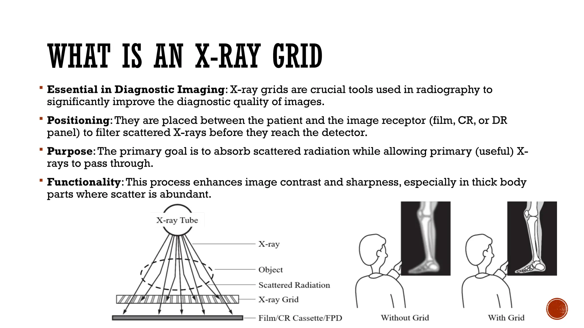
Essential in Diagnostic Imaging: X-ray grids are crucial tools used in radiography to
significantly improve the diagnostic quality of images.
Positioning:They are placed between the patient and the image receptor (film, CR, or DR
panel) to filter scattered X-rays before they reach the detector.
Purpose:The primary goal is to absorb scattered radiation while allowing primary (useful) X-
rays to pass through.
Functionality:This process enhances image contrast and sharpness, especially in thick body
parts where scatter is abundant.
3.
SCATTERED RADIATION
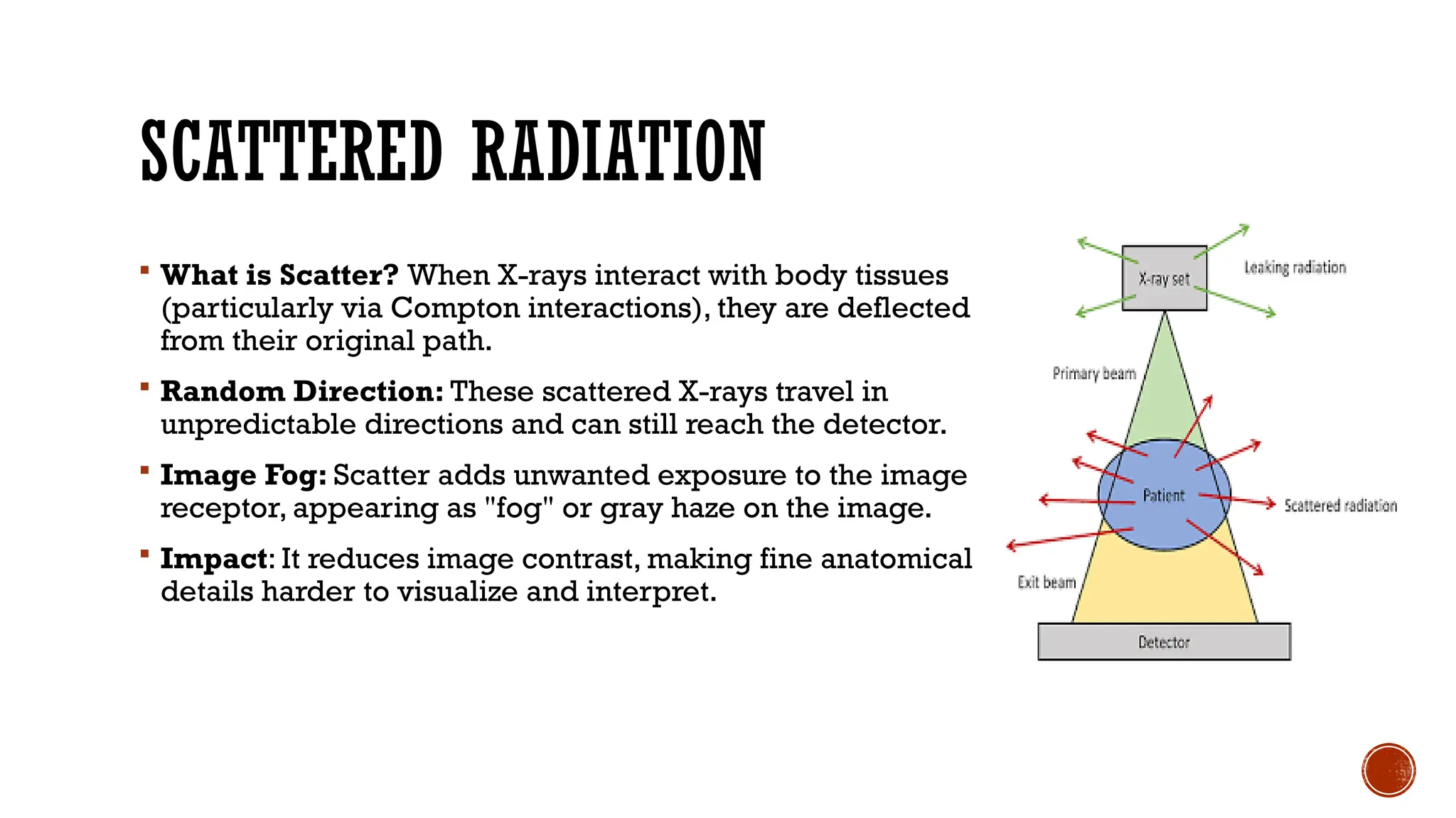
Whatis Scatter? When X-rays interact with body tissues
(particularly via Compton interactions), they are deflected
from their original path.
Random Direction: These scattered X-rays travel in
unpredictable directions and can still reach the detector.
Image Fog: Scatter adds unwanted exposure to the image
receptor, appearing as "fog" or gray haze on the image.
Impact: It reduces image contrast, making fine anatomical
details harder to visualize and interpret.
4.
IMPACT OF SCATTERON IMAGE QUALITY
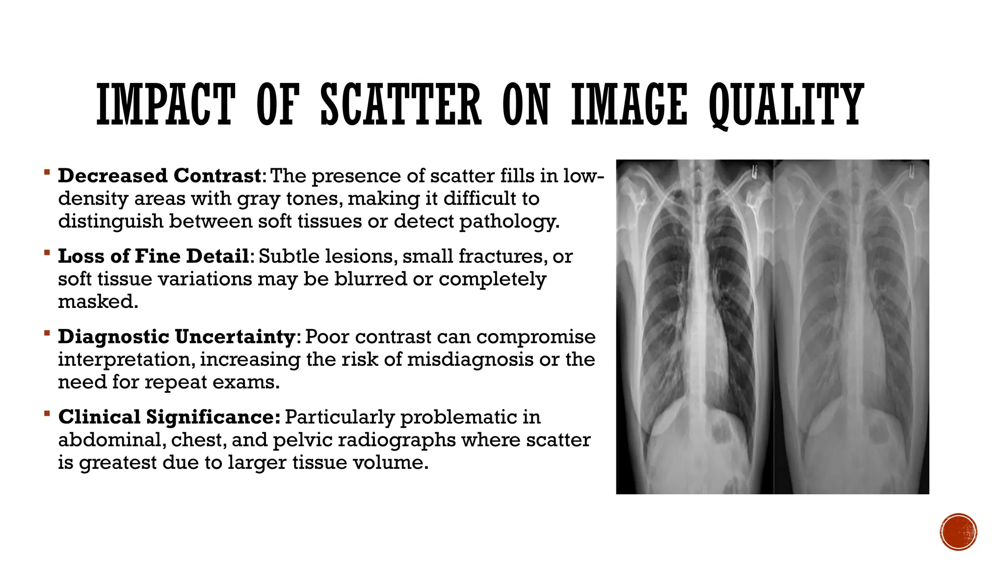
Decreased Contrast:The presence of scatter fills in low-
density areas with gray tones, making it difficult to
distinguish between soft tissues or detect pathology.
Loss of Fine Detail: Subtle lesions, small fractures, or
soft tissue variations may be blurred or completely
masked.
Diagnostic Uncertainty: Poor contrast can compromise
interpretation, increasing the risk of misdiagnosis or the
need for repeat exams.
Clinical Significance: Particularly problematic in
abdominal, chest, and pelvic radiographs where scatter
is greatest due to larger tissue volume.
5.
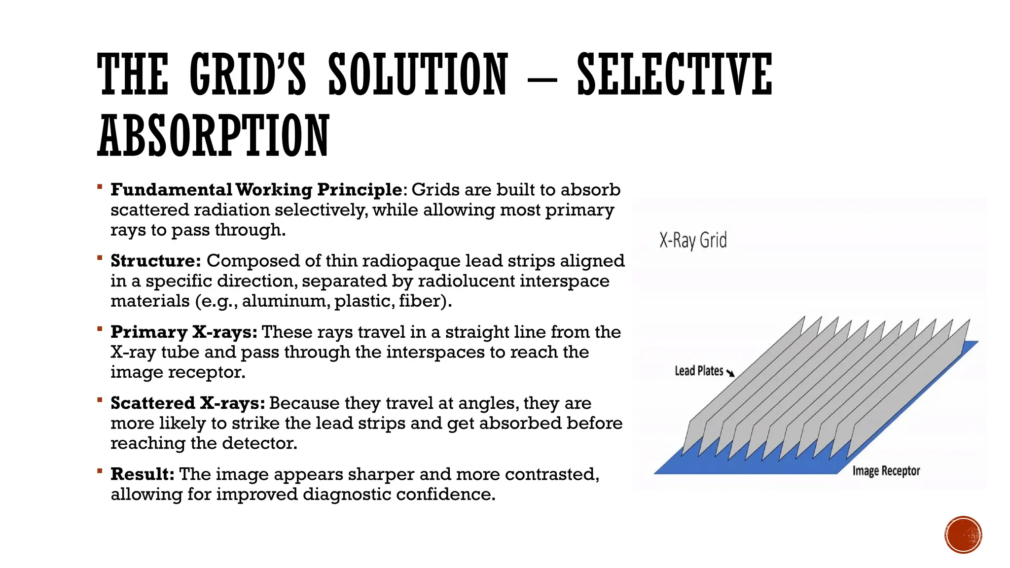
THE GRID’S SOLUTION– SELECTIVE
ABSORPTION
FundamentalWorking Principle: Grids are built to absorb
scattered radiation selectively, while allowing most primary
rays to pass through.
Structure: Composed of thin radiopaque lead strips aligned
in a specific direction, separated by radiolucent interspace
materials (e.g., aluminum, plastic, fiber).
Primary X-rays: These rays travel in a straight line from the
X-ray tube and pass through the interspaces to reach the
image receptor.
Scattered X-rays: Because they travel at angles, they are
more likely to strike the lead strips and get absorbed before
reaching the detector.
Result: The image appears sharper and more contrasted,
allowing for improved diagnostic confidence.
6.
TYPES OF X-RAYGRIDS
Grid Design Variations: X-ray grids are classified
based on the orientation of lead strips and the material
used in the interspace.
Major Types: Include linear (parallel), focused, and
cross-hatch (crisscross) grids—each engineered for
specific radiographic contexts.
Interspace Choices: Include aluminum, plastic fiber, or
carbon fiber, which impact grid weight and
performance.
Clinical Relevance: Grid type selection depends on
body part thickness, required image quality, and
radiographic technique.
7.
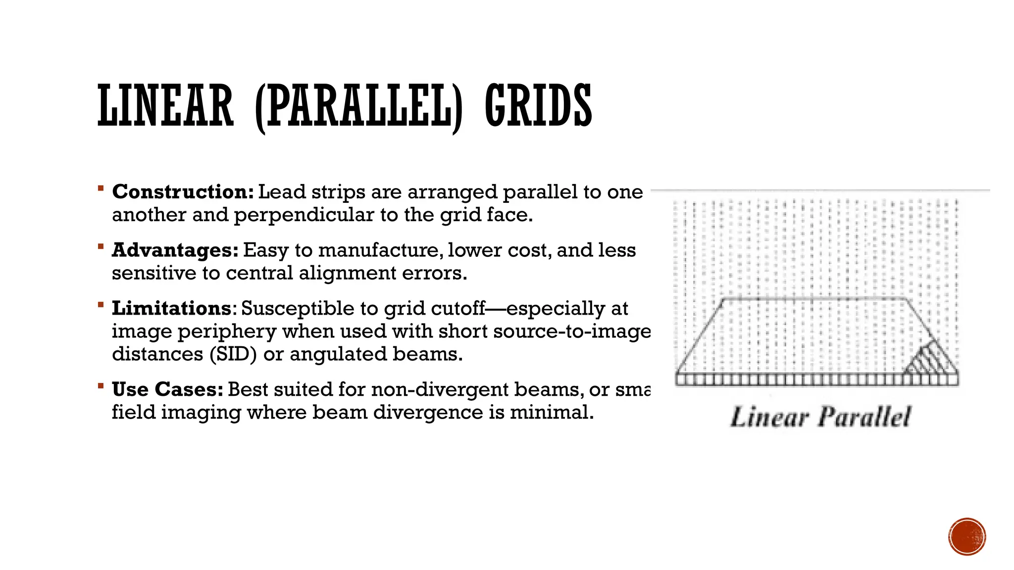
LINEAR (PARALLEL) GRIDS
Construction: Lead strips are arranged parallel to one
another and perpendicular to the grid face.
Advantages: Easy to manufacture, lower cost, and less
sensitive to central alignment errors.
Limitations: Susceptible to grid cutoff—especially at
image periphery when used with short source-to-image
distances (SID) or angulated beams.
Use Cases: Best suited for non-divergent beams, or small-
field imaging where beam divergence is minimal.
8.
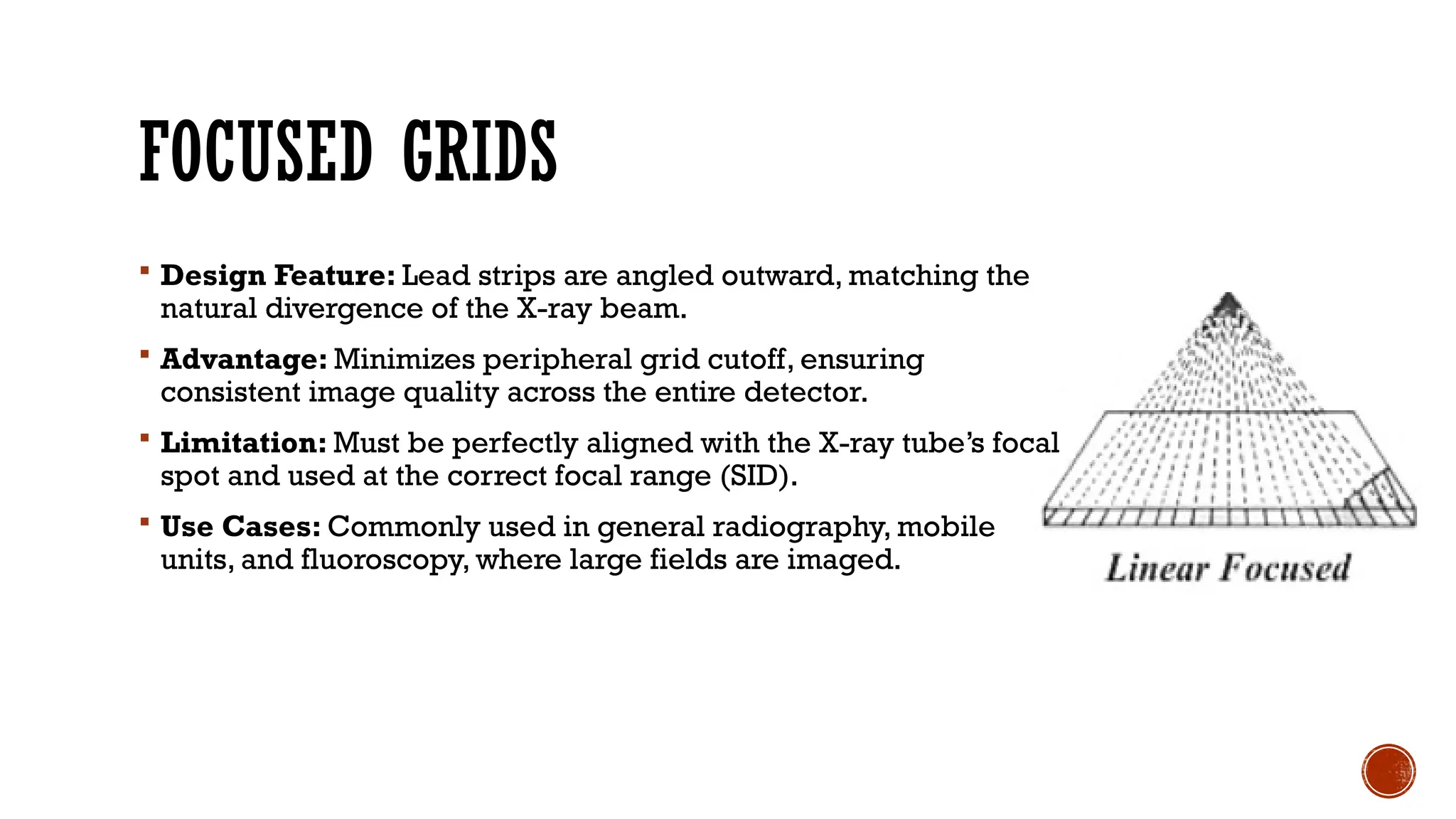
FOCUSED GRIDS
DesignFeature: Lead strips are angled outward, matching the
natural divergence of the X-ray beam.
Advantage: Minimizes peripheral grid cutoff, ensuring
consistent image quality across the entire detector.
Limitation: Must be perfectly aligned with the X-ray tube’s focal
spot and used at the correct focal range (SID).
Use Cases: Commonly used in general radiography, mobile
units, and fluoroscopy, where large fields are imaged.
9.
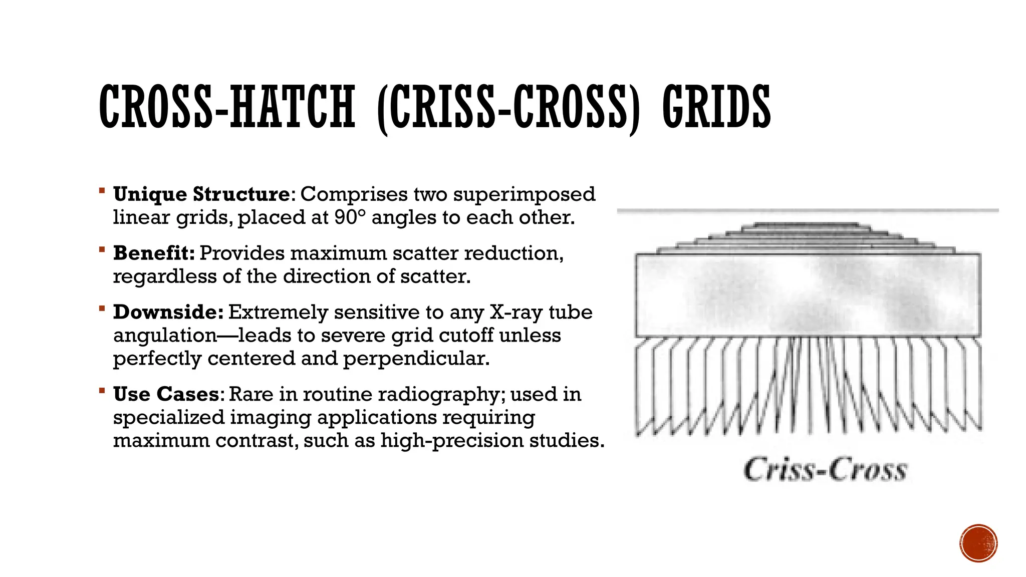
CROSS-HATCH (CRISS-CROSS) GRIDS
Unique Structure: Comprises two superimposed
linear grids, placed at 90° angles to each other.
Benefit: Provides maximum scatter reduction,
regardless of the direction of scatter.
Downside: Extremely sensitive to any X-ray tube
angulation—leads to severe grid cutoff unless
perfectly centered and perpendicular.
Use Cases: Rare in routine radiography; used in
specialized imaging applications requiring
maximum contrast, such as high-precision studies.
10.
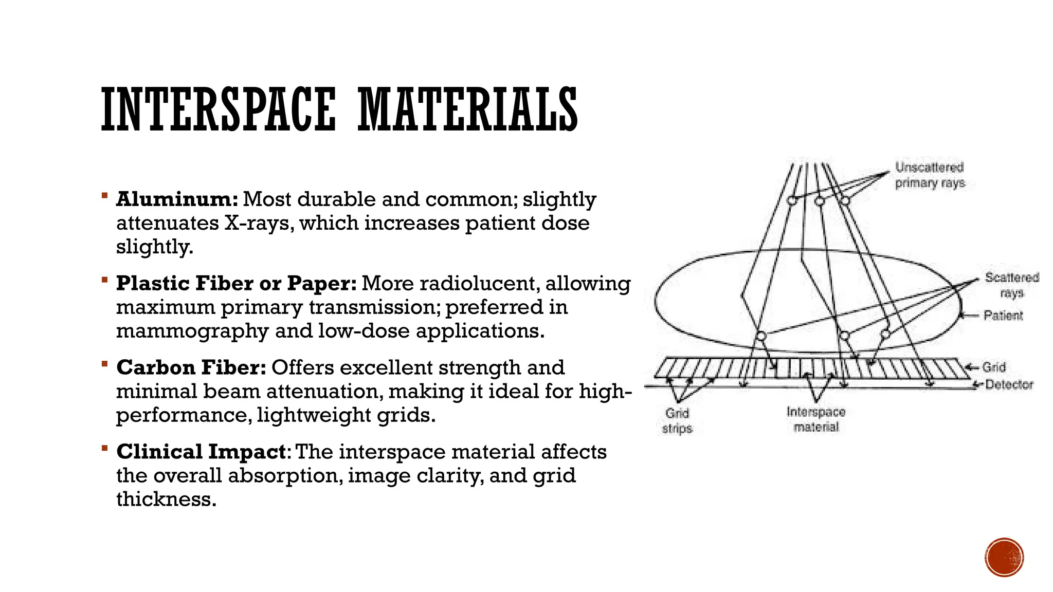
INTERSPACE MATERIALS
Aluminum:Most durable and common; slightly
attenuates X-rays, which increases patient dose
slightly.
Plastic Fiber or Paper: More radiolucent, allowing
maximum primary transmission; preferred in
mammography and low-dose applications.
Carbon Fiber: Offers excellent strength and
minimal beam attenuation, making it ideal for high-
performance, lightweight grids.
Clinical Impact:The interspace material affects
the overall absorption, image clarity, and grid
thickness.
11.
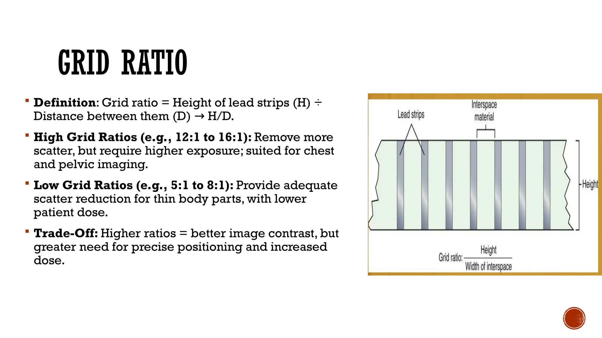
GRID RATIO
Definition:Grid ratio = Height of lead strips (H) ÷
Distance between them (D) H/D.
→
High Grid Ratios (e.g., 12:1 to 16:1): Remove more
scatter, but require higher exposure; suited for chest
and pelvic imaging.
Low Grid Ratios (e.g., 5:1 to 8:1): Provide adequate
scatter reduction for thin body parts, with lower
patient dose.
Trade-Off: Higher ratios = better image contrast, but
greater need for precise positioning and increased
dose.
12.
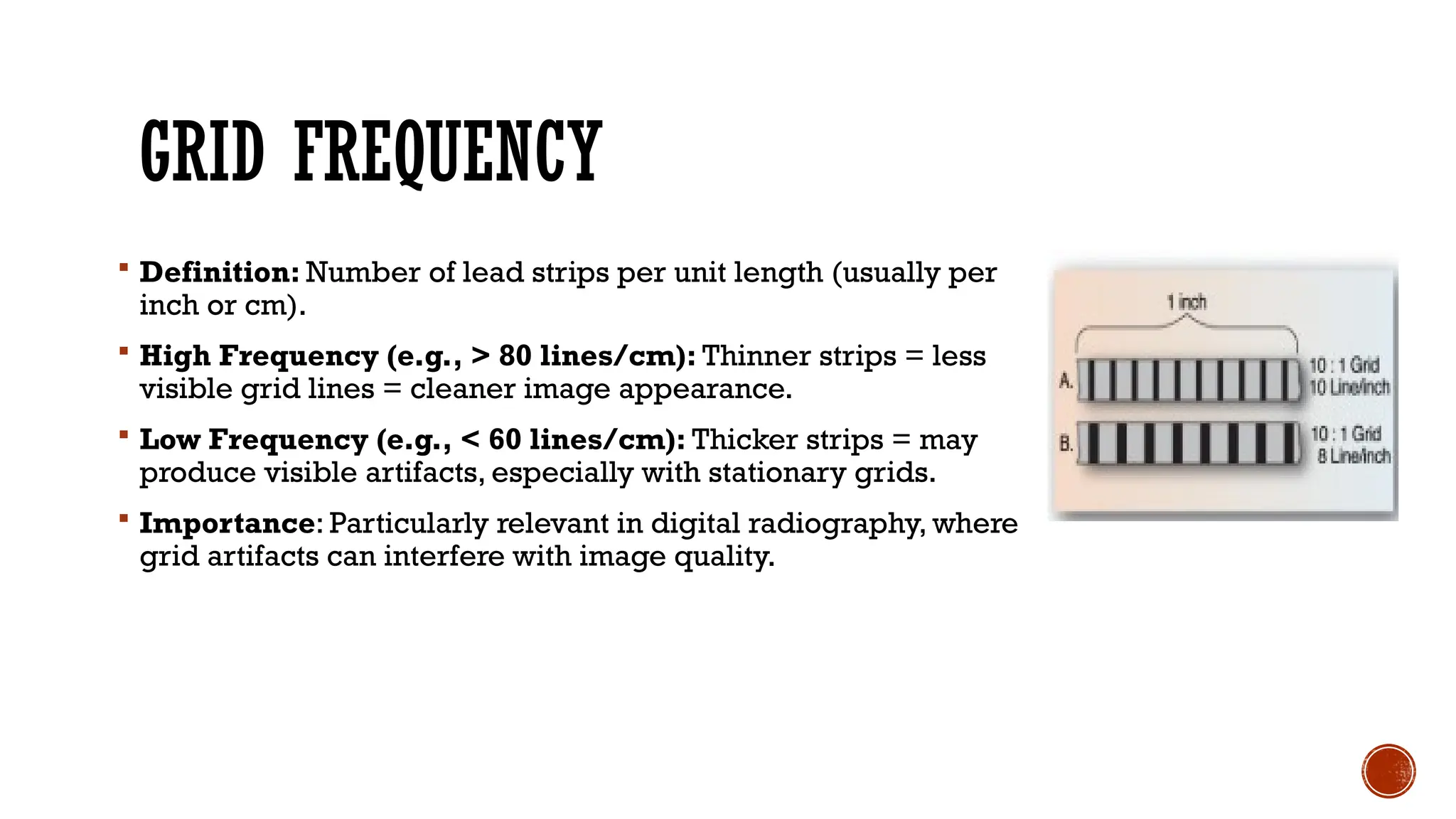
GRID FREQUENCY
Definition:Number of lead strips per unit length (usually per
inch or cm).
High Frequency (e.g., > 80 lines/cm): Thinner strips = less
visible grid lines = cleaner image appearance.
Low Frequency (e.g., < 60 lines/cm): Thicker strips = may
produce visible artifacts, especially with stationary grids.
Importance: Particularly relevant in digital radiography, where
grid artifacts can interfere with image quality.
13.
GRID MOVEMENTS &APPLICATIONS
The Problem ofVisible Grid Lines
Artifact Risk: When using a stationary grid, the lead strips may appear as lines on
the final radiograph.
Visibility Factors: More apparent in low-frequency grids and with digital
detectors.
Image Distraction: Grid lines can mimic pathology or reduce diagnostic
confidence.
Solution: Use moving grids (Bucky mechanism) to eliminate visibility.
14.
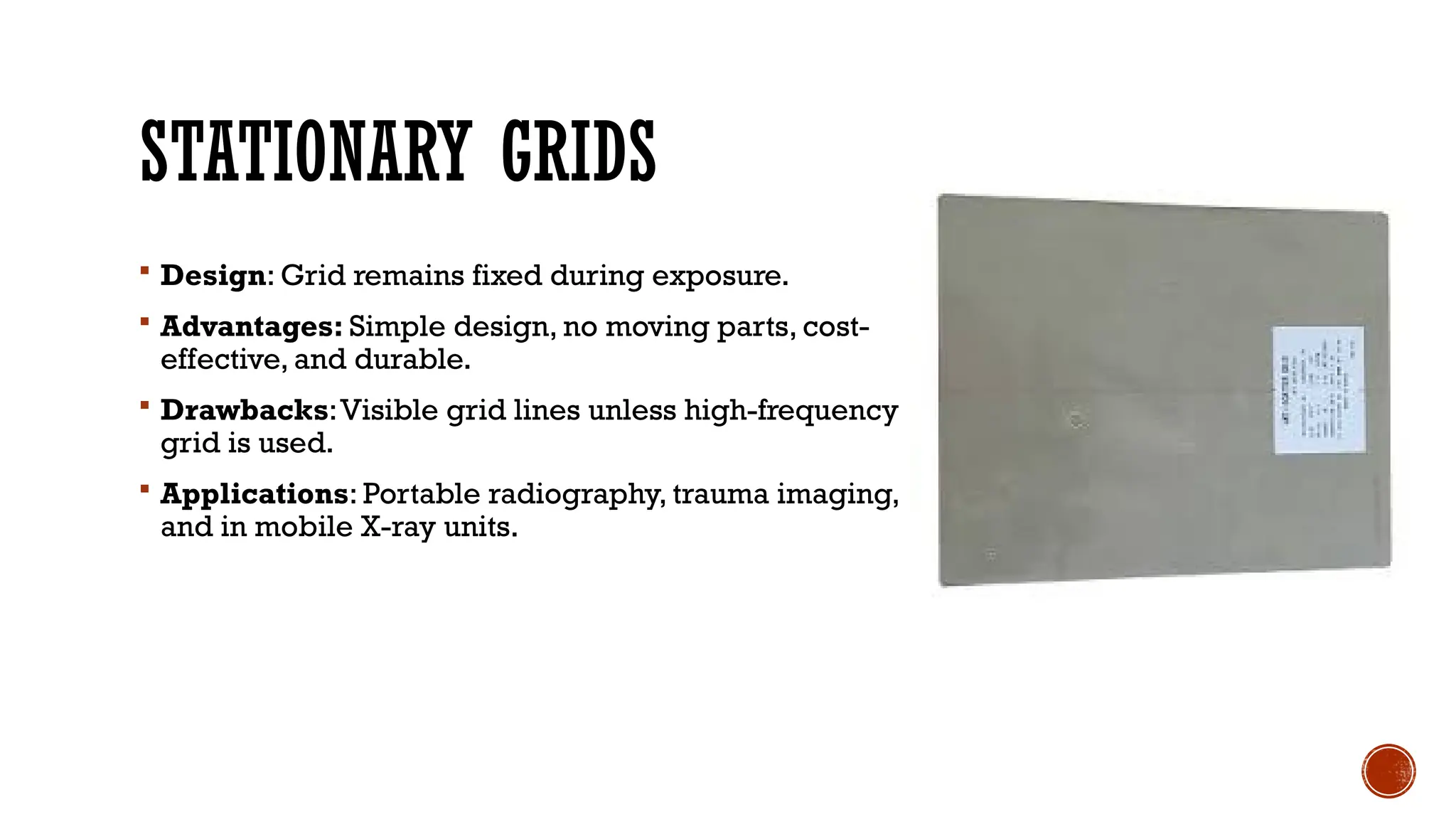
STATIONARY GRIDS
Design:Grid remains fixed during exposure.
Advantages: Simple design, no moving parts, cost-
effective, and durable.
Drawbacks:Visible grid lines unless high-frequency
grid is used.
Applications: Portable radiography, trauma imaging,
and in mobile X-ray units.
15.
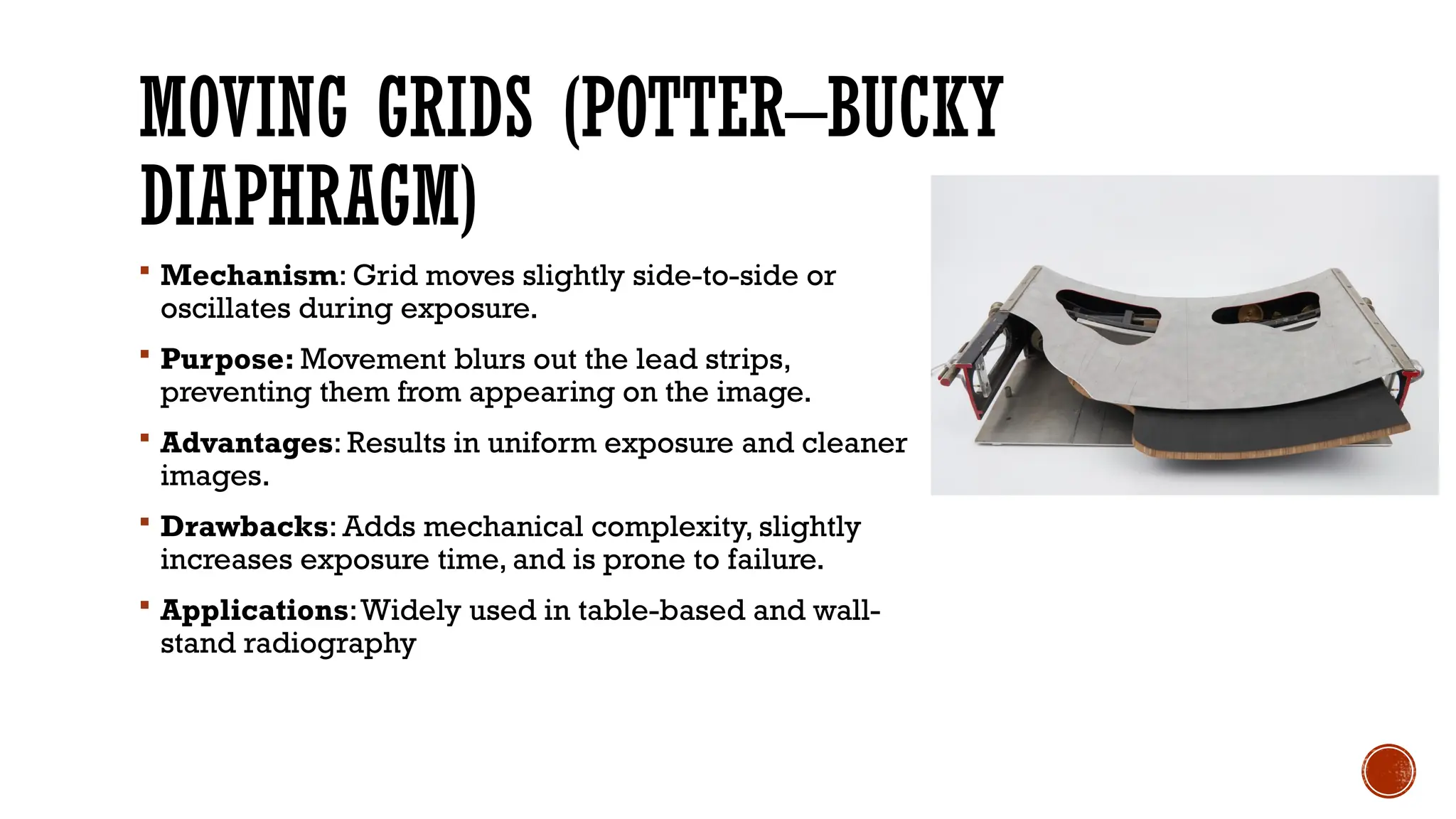
MOVING GRIDS (POTTER–BUCKY
DIAPHRAGM)
Mechanism: Grid moves slightly side-to-side or
oscillates during exposure.
Purpose: Movement blurs out the lead strips,
preventing them from appearing on the image.
Advantages: Results in uniform exposure and cleaner
images.
Drawbacks: Adds mechanical complexity, slightly
increases exposure time, and is prone to failure.
Applications:Widely used in table-based and wall-
stand radiography
16.
RECIPROCATING GRID (BACK-AND-FORTH
MOTION)
Movement: The grid moves linearly in one direction, usually side-to-side.
Mechanism: Powered by a motor, it travels a few centimeters back and forth
during the X-ray exposure.
Speed: Movement is synchronized with the exposure time to ensure lead lines are
blurred.
Advantages:
Effectively removes grid lines from the image
Most common in modern Bucky systems.
Applications: Routine radiography in fixed X-ray tables and upright stands
17.
OSCILLATING GRID (CIRCULAROR
ELLIPTICAL MOTION)
Movement: The grid vibrates in a circular or oscillatory motion during exposure.
Mechanism: Suspended by springs and moved by an electromagnet, allowing
smooth multidirectional motion.
Advantages:
Less mechanical wear than reciprocating systems.
Smooth motion reduces chances of artifacts.
Applications: Advanced radiographic systems, where consistent image quality is
crucial.
18.
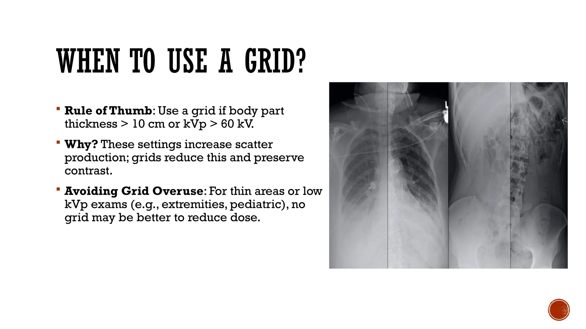
WHEN TO USEA GRID?
Rule of Thumb: Use a grid if body part
thickness > 10 cm or kVp > 60 kV.
Why? These settings increase scatter
production; grids reduce this and preserve
contrast.
Avoiding Grid Overuse: For thin areas or low
kVp exams (e.g., extremities, pediatric), no
grid may be better to reduce dose.
19.
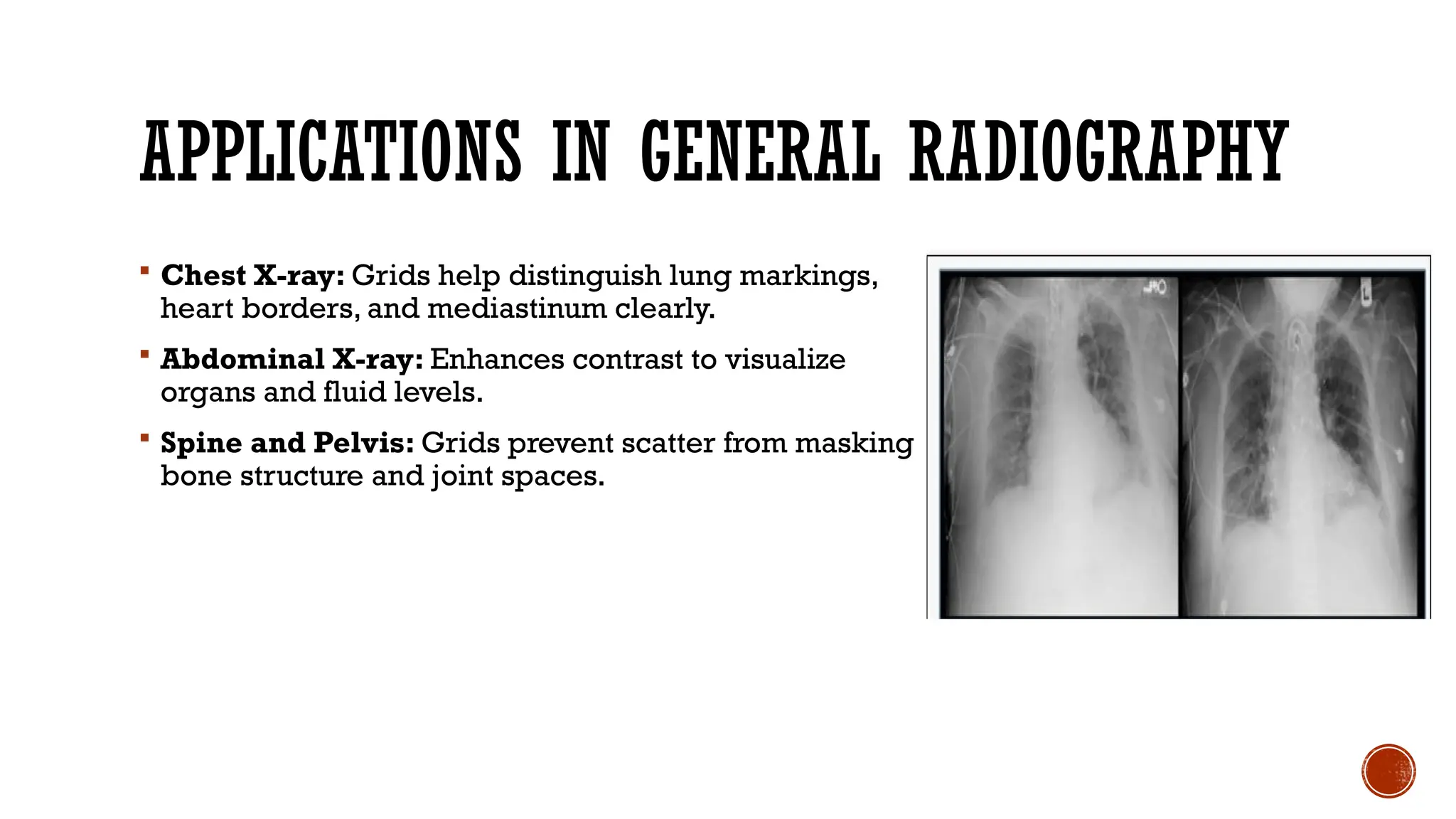
APPLICATIONS IN GENERALRADIOGRAPHY
Chest X-ray: Grids help distinguish lung markings,
heart borders, and mediastinum clearly.
Abdominal X-ray: Enhances contrast to visualize
organs and fluid levels.
Spine and Pelvis: Grids prevent scatter from masking
bone structure and joint spaces.
20.
OTHER KEY APPLICATIONS
Mammography: Uses specialized high-ratio grids with very fine strips to preserve
microcalcification visibility.
Fluoroscopy: Dynamic imaging with grids reduces scatter during real-time
procedures like angiography.
Mobile Imaging: Grids improve quality in bedside and trauma radiography,
despite portability constraints.
CT : Uses anti-scatter collimators, not conventional grids—but based on the same
principle.
21.
GRID EVALUATION &QUALITY CONTROL
Why Evaluate Grids?
Maintain Quality: Ensures grid is providing maximum scatter rejection.
Patient Safety: Helps optimize exposure, keeping dose as low as reasonably
achievable (ALARA).
Equipment Reliability: Detects issues like grid damage, warping, or
misalignment early.
QC Compliance: Part of institutional and regulatory quality assurance programs.
22.
CONTRAST IMPROVEMENT FACTOR(CIF)
Definition: Measures how much the grid improves image
contrast.
Formula: CIF = Contrast with grid ÷ Contrast without grid.
Interpretation: A higher CIF value means better scatter
rejection and image contrast.
Used For: Comparing grid efficiency across different models
and manufacturers.
23.
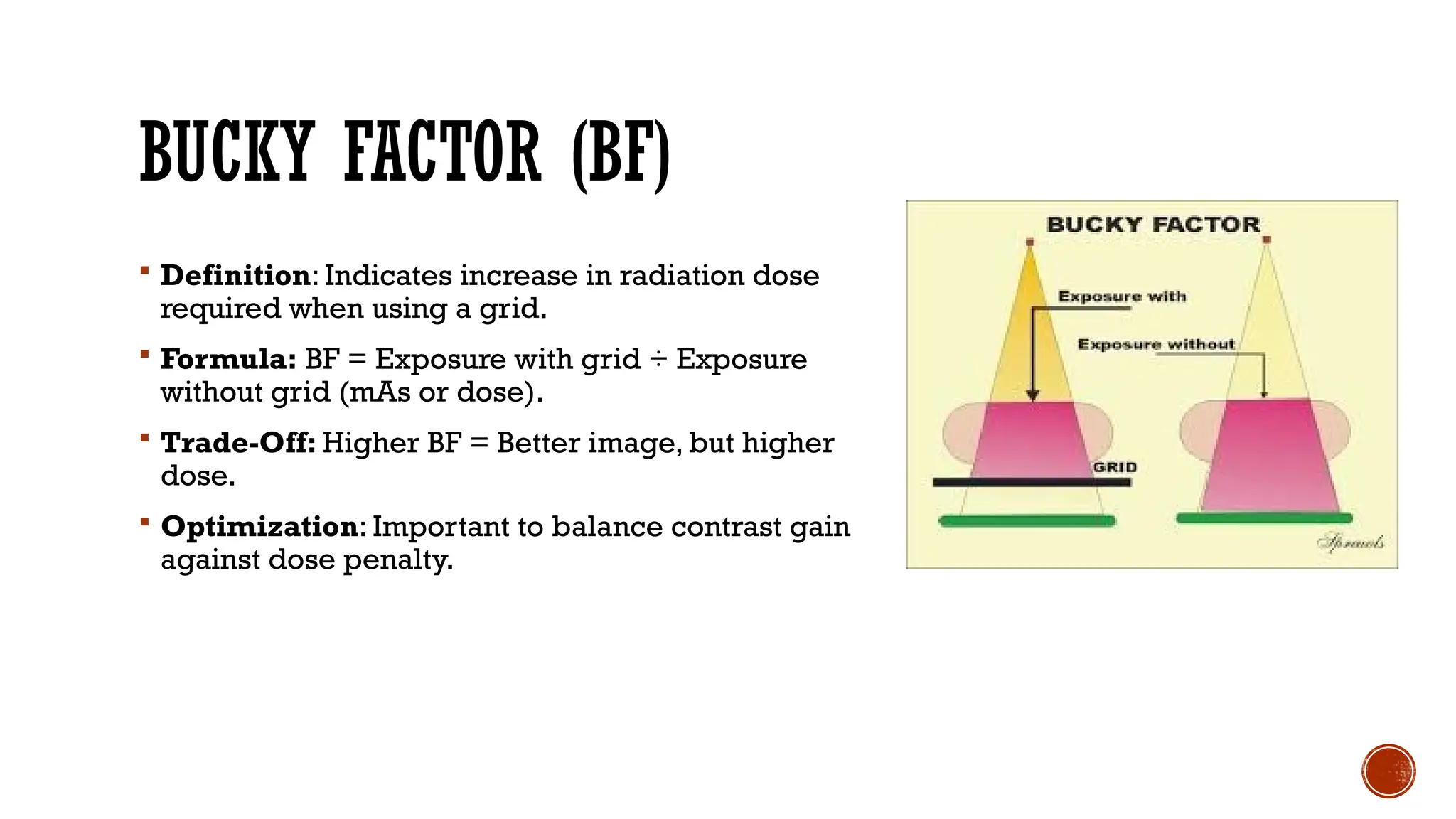
BUCKY FACTOR (BF)
Definition: Indicates increase in radiation dose
required when using a grid.
Formula: BF = Exposure with grid ÷ Exposure
without grid (mAs or dose).
Trade-Off: Higher BF = Better image, but higher
dose.
Optimization: Important to balance contrast gain
against dose penalty.
24.
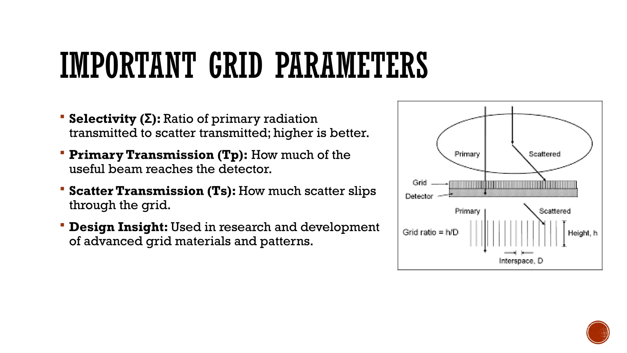
IMPORTANT GRID PARAMETERS
Selectivity ( ):
Σ Ratio of primary radiation
transmitted to scatter transmitted; higher is better.
Primary Transmission (Tp): How much of the
useful beam reaches the detector.
Scatter Transmission (Ts): How much scatter slips
through the grid.
Design Insight: Used in research and development
of advanced grid materials and patterns.
25.
METHODS FOR GRIDEVALUATION
Phantom Testing: Use test objects to check contrast and uniformity under clinical
conditions.
Dosimetry: Assess patient and entrance skin dose using meters or TLDs.
Visual Inspection: Look for grid lines, artifacts, or alignment issues on actual
clinical images.
Specs Comparison: Match performance with manufacturer's guidelines and
tolerances.
26.
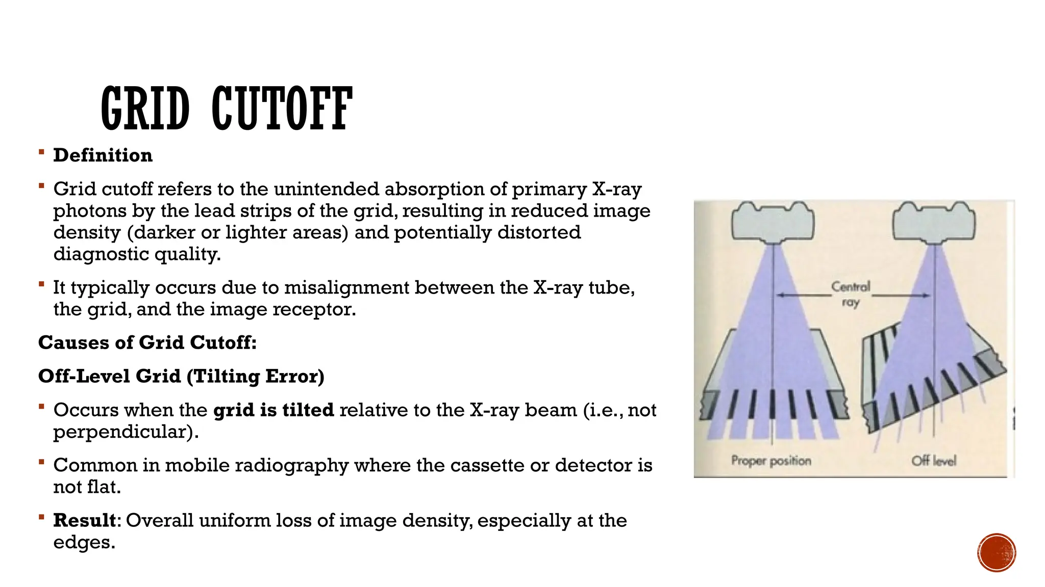
GRID CUTOFF
Definition
Grid cutoff refers to the unintended absorption of primary X-ray
photons by the lead strips of the grid, resulting in reduced image
density (darker or lighter areas) and potentially distorted
diagnostic quality.
It typically occurs due to misalignment between the X-ray tube,
the grid, and the image receptor.
Causes of Grid Cutoff:
Off-Level Grid (Tilting Error)
Occurs when the grid is tilted relative to the X-ray beam (i.e., not
perpendicular).
Common in mobile radiography where the cassette or detector is
not flat.
Result: Overall uniform loss of image density, especially at the
edges.
27.
CONTD.
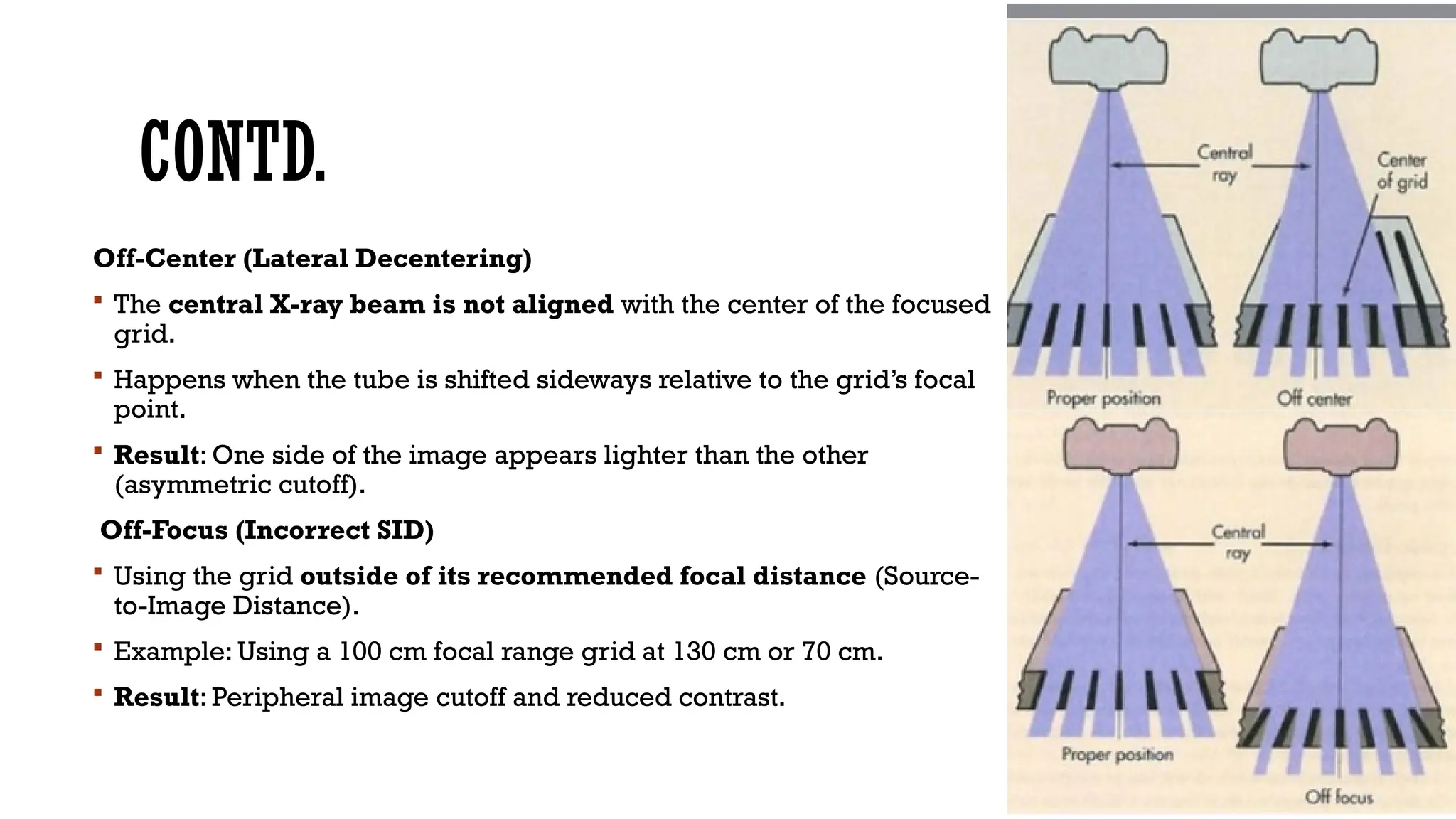
Off-Center (Lateral Decentering)
The central X-ray beam is not aligned with the center of the focused
grid.
Happens when the tube is shifted sideways relative to the grid’s focal
point.
Result: One side of the image appears lighter than the other
(asymmetric cutoff).
Off-Focus (Incorrect SID)
Using the grid outside of its recommended focal distance (Source-
to-Image Distance).
Example: Using a 100 cm focal range grid at 130 cm or 70 cm.
Result: Peripheral image cutoff and reduced contrast.
28.
CONTD.
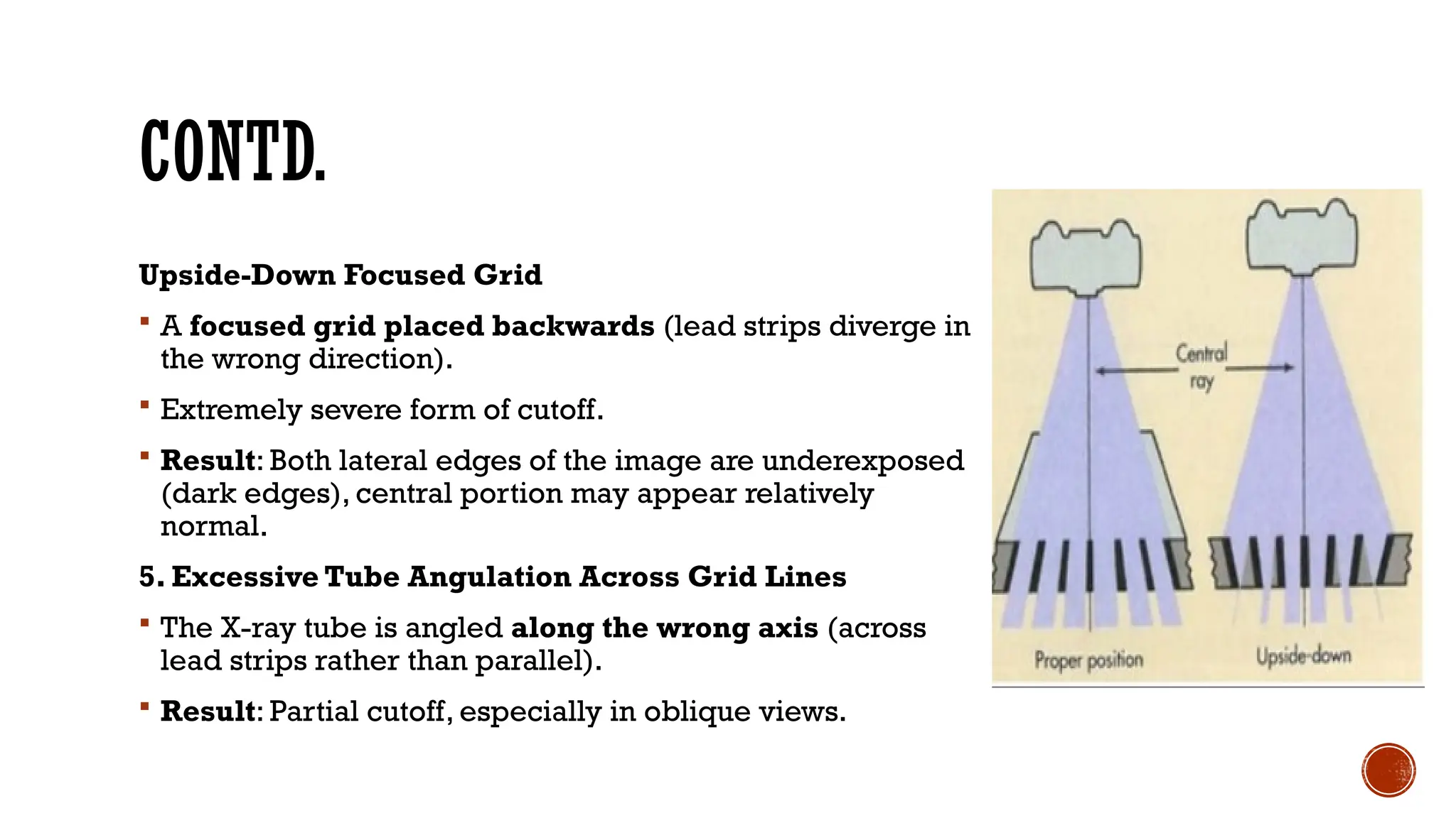
Upside-Down Focused Grid
A focused grid placed backwards (lead strips diverge in
the wrong direction).
Extremely severe form of cutoff.
Result: Both lateral edges of the image are underexposed
(dark edges), central portion may appear relatively
normal.
5. Excessive Tube Angulation Across Grid Lines
The X-ray tube is angled along the wrong axis (across
lead strips rather than parallel).
Result: Partial cutoff, especially in oblique views.
29.
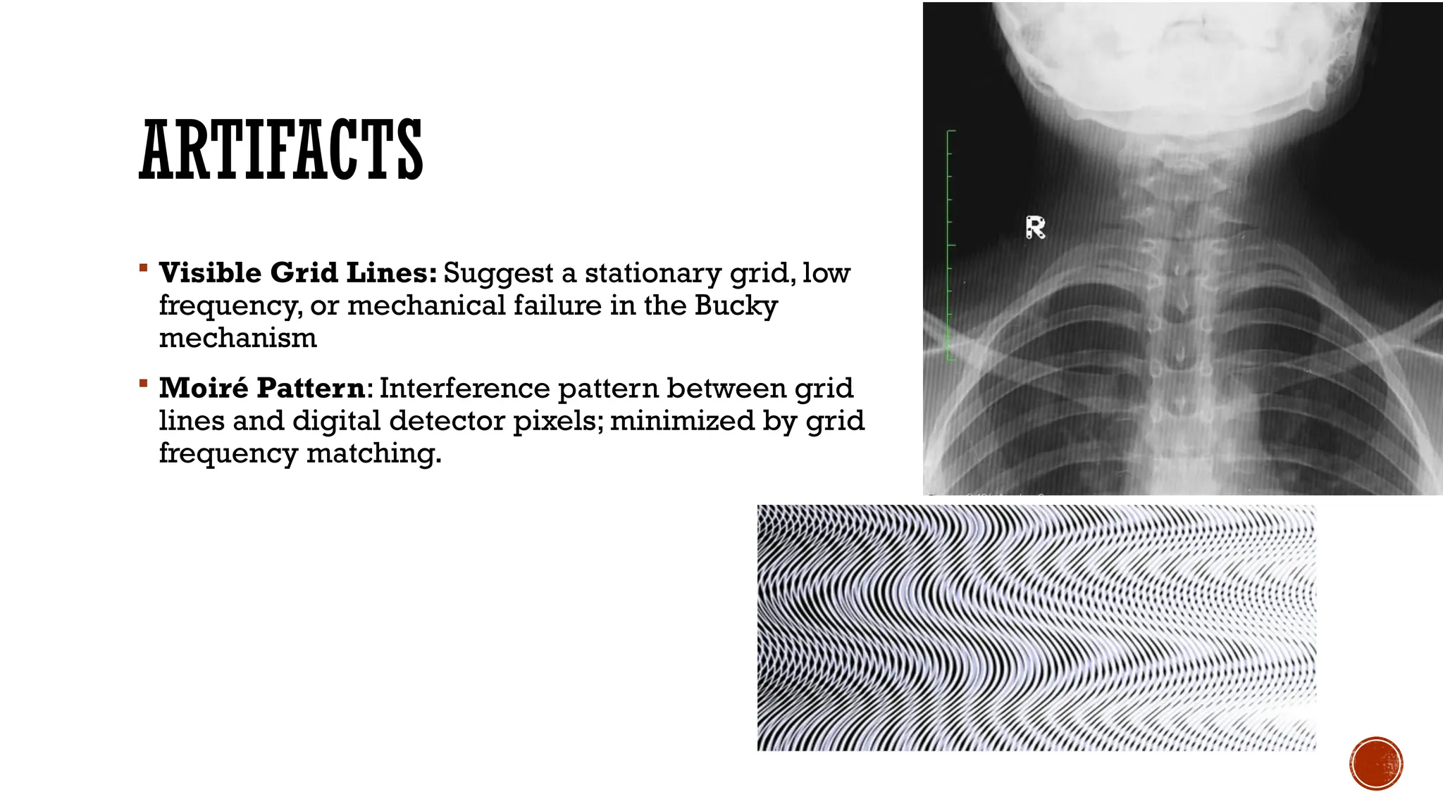
ARTIFACTS
Visible GridLines: Suggest a stationary grid, low
frequency, or mechanical failure in the Bucky
mechanism
Moiré Pattern: Interference pattern between grid
lines and digital detector pixels; minimized by grid
frequency matching.
30.
THE ROLE OFGRIDS IN PATIENT CARE
Enhance Diagnostic Accuracy: By improving contrast and detail, grids help in
identifying subtle lesions or abnormalities.
Aid in Disease Detection: Clearer images reduce diagnostic uncertainty,
minimizing repeat exposures.
Justified Dose Increase: While grids raise patient dose, the gain in clinical
information makes it worthwhile.
Standard of Care: Integral to modern imaging systems in maintaining high-quality
patient care.
31.
SUMMARY
X-ray gridsselectively absorb scatter, preserving diagnostic detail.
Their use is crucial in thicker body parts and at higher kVp settings.
Grid types: linear, focused, and crisscross, are suited to different imaging needs.
Moving grids help avoid visible artifacts.
Grid ratio and frequency impact image quality and dose.
Regular quality control ensures consistent grid performance.
Editor's Notes
#1 Welcome to this presentation on X-ray grids. Today, we’ll explore their principles, types, movement, applications, and how they enhance radiographic image quality.
#2 X-ray grids are used to remove scattered radiation, which otherwise degrades image quality. They are placed between the patient and the detector to improve contrast and detail.
#3 When X-rays interact with the patient, scattered radiation is produced. This scatter travels randomly, degrading image contrast and making diagnosis more difficult.
#4 Scattered radiation 'fogs' the image. It blurs fine structures, reduces contrast, and can potentially obscure important findings, leading to diagnostic errors.
#5 Grids allow primary radiation to pass through while absorbing scattered rays with their lead strips. This selective absorption improves image clarity.
#6 Grids vary by their design—linear, focused, or cross-hatched. The choice depends on imaging needs and the patient anatomy.
#7 Linear grids are easy to use and manufacture, but they can cause grid cutoff at the edges if not aligned well.
#8 Focused grids are the most commonly used type, offering even image quality across the field if aligned correctly.
#9 Cross-hatched grids remove scatter in all directions but are rarely used due to strict alignment requirements.
#10 The interspace material affects grid weight, thickness, and attenuation. Carbon fiber offers optimal performance.
#11 Grid ratio impacts how effectively scatter is removed. Higher ratios are used for thicker anatomy or higher energy imaging.
#12 Grid frequency determines how visible grid lines are in images. High-frequency grids reduce artifacts, especially in digital imaging.
#13 Stationary grids often result in visible lines on the image, which can distract or obscure details.
#14 Stationary grids are simple but may produce visible artifacts. They are commonly used in mobile X-ray systems.
#15 Moving grids eliminate the appearance of grid lines by oscillating during the exposure. They are used in bucky systems. Potter-Bucky diaphragm used in radiology, England, 1940-1950
#18 Grids are generally used for thicker body parts or higher kVp techniques where scatter levels are high.
#19 Grids are critical in imaging areas with high tissue density and detail, such as the chest, abdomen, and spine.
#20 Grids or grid-like systems are used in specialized modalities to enhance image quality and maintain dose efficiency.
#21 Regular evaluation ensures the grid is functioning correctly and not introducing artifacts or unnecessary radiation dose.
#22 CIF is used to quantify how much better the image contrast is with a grid. A higher CIF means better image quality.
#23 The Bucky Factor tells us how much more radiation is needed when a grid is used. This is important for dose calculations.
#24 Selectivity and transmission ratios are technical measures of grid performance, used in design and quality control.
#25 Various methods, including phantoms and dosimeters, are used to assess grid performance and ensure clinical safety.
#27 Prevention Tips:
Always align the X-ray tube to the center of the grid.
Use correct SID as per the grid’s design (e.g., 100–130 cm).
Ensure the grid is level and not upside-down.
Angle the tube parallel to the grid lines if angulation is required.
Verify correct grid placement in portable settings.
#28 Visual Indicators of Grid Cutoff:
Dark bands or light streaks on the radiograph.
Asymmetric density (left/right differences).
Overall gray, foggy image with loss of diagnostic detail.
Mimics underexposure or improper positioning.
#29 Artifacts like cutoff and moiré patterns can degrade images. Proper grid usage and alignment help prevent these issues.