![Chapter 2
Background on Nonlinear Systems and Control
In this chapter, we review some basic results on the analysis and control of nonlinear
systems. This review is not intended to be exhaustive but to provide the reader with
the necessary background for the results presented in the subsequent chapters. The
results presented in this chapter are standard in the nonlinear systems and control
literature. For detailed discussion and proofs of the results, the reader may refer to
the classic books [72, 76].
2.1 Notation
Throughout this book, the operator |·| is used to denote the absolute value of a scalar
and the operator · is used to denote Euclidean norm of a vector, while we use
· Q to denote the square of a weighted Euclidean norm, i.e., x Q = xT Qx for all
x ∈ Rn. The symbol Ωr is used to denote the set Ωr := {x ∈ Rn : V (x) ≤ r} where
V is a scalar positive definite, continuous differentiable function and V (0) = 0, and
the operator ‘/’ denotes set subtraction, that is, A/B := {x ∈ Rn : x ∈ A,x /∈ B}.
The notation R = [r1 r2] is used to denote the augmented vector R ∈ Rm+n com-
prising the vectors r1 ∈ Rm and r2 ∈ Rn. The notation x(T +) denotes the limit of
the trajectory x(t) as T is approached from the right, i.e., x(T +) = limt→T + x(t).
The notation Lf h denotes the standard Lie derivative of a scalar function h(·) with
respect to the vector function f (·), i.e., Lf h(x) = ∂h
∂x f (x).
2.2 Nonlinear Systems
In this book, we deal with a class of time invariant nonlinear systems that can be
described by the following state-space model:
˙x = f (x,u), (2.1)
P. Mhaskar et al., Fault-Tolerant Process Control, DOI 10.1007/978-1-4471-4808-1_2,
© Springer-Verlag London 2013
9](https://image.slidesharecdn.com/fault-tolerantprocesscontrol-130716022729-phpapp01/85/Fault-tolerant-process-control-1-320.jpg)
![Chapter 2
Background on Nonlinear Systems and Control
In this chapter, we review some basic results on the analysis and control of nonlinear
systems. This review is not intended to be exhaustive but to provide the reader with
the necessary background for the results presented in the subsequent chapters. The
results presented in this chapter are standard in the nonlinear systems and control
literature. For detailed discussion and proofs of the results, the reader may refer to
the classic books [72, 76].
2.1 Notation
Throughout this book, the operator |·| is used to denote the absolute value of a scalar
and the operator · is used to denote Euclidean norm of a vector, while we use
· Q to denote the square of a weighted Euclidean norm, i.e., x Q = xT Qx for all
x ∈ Rn. The symbol Ωr is used to denote the set Ωr := {x ∈ Rn : V (x) ≤ r} where
V is a scalar positive definite, continuous differentiable function and V (0) = 0, and
the operator ‘/’ denotes set subtraction, that is, A/B := {x ∈ Rn : x ∈ A,x /∈ B}.
The notation R = [r1 r2] is used to denote the augmented vector R ∈ Rm+n com-
prising the vectors r1 ∈ Rm and r2 ∈ Rn. The notation x(T +) denotes the limit of
the trajectory x(t) as T is approached from the right, i.e., x(T +) = limt→T + x(t).
The notation Lf h denotes the standard Lie derivative of a scalar function h(·) with
respect to the vector function f (·), i.e., Lf h(x) = ∂h
∂x f (x).
2.2 Nonlinear Systems
In this book, we deal with a class of time invariant nonlinear systems that can be
described by the following state-space model:
˙x = f (x,u), (2.1)
P. Mhaskar et al., Fault-Tolerant Process Control, DOI 10.1007/978-1-4471-4808-1_2,
© Springer-Verlag London 2013
9](https://image.slidesharecdn.com/fault-tolerantprocesscontrol-130716022729-phpapp01/75/Fault-tolerant-process-control-1-2048.jpg)
![2.3 Stability of Nonlinear Systems 17
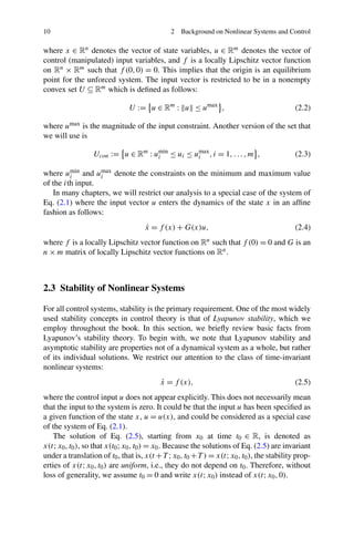
2.3.6 Input-to-State Stability
It is of interest to extend stability concepts to systems with disturbance inputs. In
the linear case represented by the system
˙x = Ax + Bθ,
it is well known that if the matrix A is Hurwitz, i.e., if the unforced system, ˙x = Ax,
is asymptotically stable, then bounded inputs θ lead to bounded states while inputs
converging to zero produce states converging to zero. Now, consider a nonlinear
system of the form
˙x = f (x,θ), (2.17)
where θ is a measurable bounded disturbance input. In general, global asymptotic
stability of the unforced system ˙x = f (x,0) does not guarantee input-to-state sta-
bility with respect to θ of the kind mentioned above. For example, the scalar system
˙x = −x + xθ (2.18)
has unbounded trajectories under the bounded input θ ≡ 2. This motivates the fol-
lowing important concept, introduced by Sontag [151].
Definition 2.5 The system of Eq. (2.17) is called input-to-state stable (ISS) with
respect to θ if for some functions γ ∈ K∞ and β ∈ KL, for every initial state x(0),
and every input θ, the corresponding solution of the system of Eq. (2.17) satisfies
the inequality
x(t) ≤ β x(0) ,t + γ θ s
[0,t] , (2.19)
where θ s
[0,t] := ess.sup{ θ(s) : s ∈ [0,t]} (supremum norm on [0,t] except for a
set of measure zero).
Since the system of Eq. (2.17) is time-invariant, the same property results if we
write
x(t) ≤ β x(t0) ,t − t0 + γ θ s
[t0,t] , ∀t ≥ t0 ≥ 0. (2.20)
The ISS property admits the following Lyapunov-like equivalent characterization:
The system of Eq. (2.17) is ISS if and only if there exists a positive-definite radially
unbounded C1 function V : Rn → R such that for some class K∞ functions α and
χ we have
∂V
∂x
f (x,θ) ≤ −α x + χ θ , ∀x,θ. (2.21)
This is, in turn, equivalent to the following “gain margin” condition:
x ≥ ρ θ =⇒
∂V
∂x
f (x,θ) ≤ −α x , (2.22)](https://image.slidesharecdn.com/fault-tolerantprocesscontrol-130716022729-phpapp01/85/Fault-tolerant-process-control-9-320.jpg)
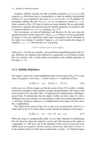
![18 2 Background on Nonlinear Systems and Control
where α,ρ ∈ K∞. Such functions V are called ISS-Lyapunov functions. If the sys-
tem of Eq. (2.17) is ISS, then θ(t) → 0 implies x(t) → 0.
The system of Eq. (2.17) is said to be locally input-to-state stable (locally ISS)
if the bound of Eq. (2.19) is valid for solutions with sufficiently small initial condi-
tions and inputs, i.e., if there exists a δ > 0 such that Eq. (2.19) is satisfied whenever
x(0) ≤ δ and θ s
[0,t] ≤ δ. It turns out that (local) asymptotic stability of the un-
forced system ˙x = f (x,0) implies local ISS.
2.4 Stabilization of Nonlinear Systems
This book is primarily about control design. Our objective is to create closed-loop
systems with desirable stability and performance properties, rather than analyze the
properties of a given system. For this reason, we are interested in an extension of
the Lyapunov function concept, called a control Lyapunov function (CLF).
Suppose that our problem for the time-invariant system
˙x = f (x,u), (2.23)
where x ∈ Rn, u ∈ R (i.e., we consider the unconstrained problem), f (0,0) = 0,
is to design a feedback control law α(x) for the control variable u such that the
equilibrium x = 0 of the closed-loop system
˙x = f x,α(x) (2.24)
is globally asymptotically stable. We can pick a function V (x) as a Lyapunov func-
tion candidate, and require that its derivative along the solutions of the system of
Eq. (2.24) satisfies ˙V ≤ −W(x), where W(x) is a positive-definite function. We
therefore need to find α(x) to guarantee that for all x ∈ Rn
∂V
∂x
(x)f x,α(x) ≤ −W(x). (2.25)
This is a difficult task. A stabilizing control law for the system of Eq. (2.23) may
exist, but it may fail to satisfy Eq. (2.25) because of a poor choice of V (x) and
W(x). A system for which a good choice of V (x) and W(x) exists is said to possess
a CLF. This notion is made more precise below.
Definition 2.6 A smooth positive-definite radially unbounded function V : Rn → R
is called a control Lyapunov function (CLF) for the system of Eq. (2.23) if
inf
u∈R
∂V
∂x
(x)f (x,u) < 0, ∀x = 0. (2.26)
The CLF concept of Artstein [9] is a generalization of Lyapunov design results
by Jacobson and Judjevic and Quinn. Artstein showed that Eq. (2.26) is not only](https://image.slidesharecdn.com/fault-tolerantprocesscontrol-130716022729-phpapp01/85/Fault-tolerant-process-control-10-320.jpg)
![2.4 Stabilization of Nonlinear Systems 19
necessary, but also sufficient for the existence of a control law satisfying Eq. (2.25),
that is, the existence of a CLF is equivalent to global asymptotic stabilizability.
For systems affine in the control, namely,
˙x = f (x) + g(x)u, f (0) = 0, (2.27)
the CLF inequality of Eq. (2.25) becomes
Lf V (x) + LgV (x)u ≤ −W(x). (2.28)
If V is a CLF for the system of Eq. (2.27), then a particular stabilizing control law
α(x), smooth for all x = 0, is given by Sontag’s formula [150]:
u = αs(x) =
⎧
⎨
⎩
−
Lf V (x)+
√
(Lf V )2(x)+(LgV )4(x)
(LgV )2(x)
LgV (x), LgV (x) = 0,
0, LgV (x) = 0.
(2.29)
It should be noted that Eq. (2.28) can be satisfied only if
LgV (x) = 0 =⇒ Lf V (x) < 0, ∀x = 0. (2.30)
The intuitive interpretation of the existence of a CLF is as follows: For any x such
that LgV (x) = 0, since there are no constraints on the input, ˙V can be made negative
by picking a ‘large enough’ control action, with an appropriate sign, to counter the
effect of possibly positive Lf V (x) term. For all x such that LgV (x) = 0, the control
action has no effect on the Lyapunov-function derivative. For it to be possible to
show stability using the CLF V , it should therefore be true that whenever LgV (x) =
0, we also have that Lf V (x) < 0. This is the requirement that is formalized in
Eq. (2.30). With such a CLF, Eq. (2.29) results in
W(x) = (Lf V )2(x) + (LgV )4(x) > 0, ∀x = 0. (2.31)
A further characterization of a stabilizing control law α(x) for the system of
Eq. (2.27) with a given CLF V is that α(x) is continuous at x = 0 if and only if
the CLF satisfies the small control property: For each ε > 0 there is a δ(ε) > 0 such
that, if x = 0 satisfies |x| ≤ δ, then there is some u with |u| < ε such that
Lf V (x) + LgV (x)u < 0. (2.32)
The main deficiency of the CLF concept as a design tool is that for most nonlinear
systems a CLF is not known. The task of finding an appropriate CLF maybe as com-
plex as that of designing a stabilizing feedback law. In the next section, we review
one commonly used tool for designing a Lyapunov-based control law that utilizes
coordinate transformations. We also note that in the presence of input constraints,
the concept of a CLF needs to be revisited, and this issue is discussed in Sect. 2.6.](https://image.slidesharecdn.com/fault-tolerantprocesscontrol-130716022729-phpapp01/85/Fault-tolerant-process-control-11-320.jpg)
![20 2 Background on Nonlinear Systems and Control
2.5 Feedback Linearization and Zero Dynamics
One of the popular methods for nonlinear control design (or alternatively, one way
to construct a Lyapunov-function for the purpose of control design) is feedback
linearization, which employs a change of coordinates and feedback control to trans-
form a nonlinear system into a system whose dynamics are linear (at least partially).
This transformation allows the construction and use of a Lyapunov function for the
control design utilizing results from linear systems analysis. A great deal of re-
search has been devoted to this subject over the last four decades, as evidenced by
the comprehensive books [72, 126] and the references therein. In this section, we
briefly review some of the basic geometric concepts that will be used in subsequent
chapters. While this book does not require the formalism of differential geometry,
we will employ Lie derivatives only for notational convenience. If f : Rn → Rn
is a vector field and h : Rn → R is a scalar function, the notation Lf h is used for
∂h
∂x f (x). It is recursively extended to
Lk
f h(x) = Lf Lk−1
f h(x) =
∂
∂x
Lk−1
f h(x) f (x).
Let us consider the following nonlinear system:
˙x = f (x) + g(x)u,
y = h(x),
(2.33)
where x ∈ Rn, u ∈ R, y ∈ R, f , g, h are analytic (i.e., infinitely differentiable)
vector functions. The derivative of the output y = h(x) is given by
˙y =
∂h
∂x
(x)f (x) +
∂h
∂x
(x)g(x)u
= Lf h(x) + Lgh(x)u. (2.34)
If Lgh(x0) = 0, then the system of Eq. (2.33) is said to have relative degree one at
x0 (note that since the functions are smooth Lgh(x0) = 0 implies that there exists a
neighborhood of x0 on which Lgh(x) = 0). In our terminology, this implies that the
output y is separated form the input u by one integration only. If Lgh(x0) = 0, there
are two cases:
(i) If there exist points arbitrarily close to x0 such that Lgh(x) = 0, then the system
of Eq. (2.33) does not have a well-defined relative degree at x0.
(ii) If there exists a neighborhood B0 of x0 such that Lgh(x) = 0 for all x ∈ B0,
then the relative degree of the system of Eq. (2.33) may be well-defined.
In case (ii), we define
ψ1(x) = h(x), ψ2(x) = Lf h(x) (2.35)](https://image.slidesharecdn.com/fault-tolerantprocesscontrol-130716022729-phpapp01/85/Fault-tolerant-process-control-12-320.jpg)
![22 2 Background on Nonlinear Systems and Control
is locally invertible and transforms, along with the feedback law of Eq. (2.40), the
system of Eq. (2.33) into
˙ζ1 = ζ2,
...
˙ζr = v,
˙η1 = Ψ1(ζ,η),
...
˙ηn−r = Ψn−r(ζ,η),
y = ζ1,
(2.42)
where Ψ1(ζ,η) = Lr+1
f h(x), Ψn−r(ζ,η) = Ln
f h(x).
The states η1,...,ηn−r have been rendered unobservable from the output y by
the control of Eq. (2.40). Hence, feedback linearization in this case is the nonlin-
ear equivalent of placing n − r poles of a linear system at the origin and canceling
the r zeros with the remaining poles. Of course, to guarantee stability, the canceled
zeros must be stable. In the nonlinear case, using the new control input v to sta-
bilize the linear subsystem of Eq. (2.42) does not guarantee stability of the whole
system, unless the stability of the nonlinear part of the system of Eq. (2.42) has been
established separately.
When v is used to keep the output y equal to zero for all t > 0, that is, when
ζ1 ≡ ··· ≡ ζr ≡ 0, the dynamics of η1,...,ηn−r are described by
˙η1 = Ψ1(0,η),
...
˙ηn−r = Ψn−r(0,η).
(2.43)
They are called the zero dynamics of the system of Eq. (2.33) because they evolve
on the subset of the state-space on which the output of the system is identically
zero. If the equilibrium at η1 = ··· = ηn−r = 0 of the zero dynamics of Eq. (2.43) is
asymptotically stable, the system of Eq. (2.33) is said to be minimum phase.
Remark 2.2 Most nonlinear analytical controllers emanating from the area of ge-
ometric control are input–output linearizing and induce a linear input–output re-
sponse in the absence of constraints [72, 81]. For the class of processes modeled by
equations of the form of Eq. (2.33) with relative order r and under the minimum
phase assumption, the appropriate linearizing state feedback controller is given by
u =
1
LgLr−1
f h(x)
v − Lr
f h(x) − β1Lr−1
f h(x) − ··· − βr−1Lf h(x) − βrh(x)
(2.44)](https://image.slidesharecdn.com/fault-tolerantprocesscontrol-130716022729-phpapp01/85/Fault-tolerant-process-control-14-320.jpg)
![2.6 Input Constraints 23
and induces the linear rth order response
dry
dtr
+ β1
dr−1y
dtr−1
+ ··· + βr−1
dy
dt
+ βry = v, (2.45)
where the tunable parameters, β1,...,βr , are essentially closed-loop time constants
that influence and shape the output response. The nominal stability of the process is
guaranteed by placing the roots of the polynomial sr + β1sr−1 + ··· + βr−1s + βr
in the open left-half of the complex plane.
2.6 Input Constraints
The presence of input constraints requires revisiting the concept of the CLF for both
linear and nonlinear systems. To understand this, consider a scalar linear system of
the form ˙x = αx +βu, with umin ≤ u ≤ umax. For the sake of simplicity and without
loss of generality, let us assume umin < 0 < umax and β > 0. For the case of scalar
systems, it is possible to determine the entire set of initial conditions from where
the system can be driven to the origin subject to input constraints (regardless of the
choice of the control law). This set is generally referred to as the null controllable
region (NCR). An explicit computation of the NCR is possible in this case because
for scalar systems (as discussed earlier) there exists a unique direction in which the
system states needs to move to achieve stability.
To determine this set, one can simply analyze the system trajectory to the left
and right of zero. Consider first x > 0, and the requirement that for x > 0, ˙x < 0.
If α < 0, ˙x < 0 ∀x > 0 (and also ˙x > 0 ∀x < 0). On the other hand, if α > 0,
˙x < 0 can only be achieved for x < −uminβ
α . Similarly, ˙x > 0 can only be achieved
for x > −umaxβ
α . The analysis reveals what was perhaps intuitive to begin with: For
linear systems, if the steady state is open-loop stable, the NCR is the entire state
space, while if the steady state is open-loop unstable, it has a finite NCR, which
in this case is {x : −umaxβ
α < x < −uminβ
α }. The same result for the NCR can also
be obtained using a CLF V (x) = x2
2 and determining the states for which ˙V < 0 is
achievable using the available control action. Furthermore, it points to the require-
ment of additional considerations when defining CLFs for systems with constrained
inputs. In particular, requiring that ˙V (x) < 0 ∀x is simply not achievable for certain
cases, at best what is achievable is that ˙V (x) < 0 ∀x ∈ NCR − {0}. The definition of
a CLF (or more appropriately, a constrained CLF) then becomes intricately linked
with the characterization of the NCR. The characterization of the NCR, however,
is an increasingly difficult (although possible, see [71]) problem when considering
non-scalar linear systems, and currently an open problem for nonlinear systems.
To understand the impact of the lack of availability of constrained CLFs
(CCLFs), let us first consider again the linear scalar system under a feedback law
of the form uc(x) = −kx, with k > 0 such that (α − kβ) < 0 under two possible
scenarios: (i) α < 0 (i.e., for the unforced system, there is an isolated equilibrium](https://image.slidesharecdn.com/fault-tolerantprocesscontrol-130716022729-phpapp01/85/Fault-tolerant-process-control-15-320.jpg)
![24 2 Background on Nonlinear Systems and Control
point at the origin and the system is stable at that operating point) and (ii) α > 0 (i.e.,
for the unforced system, there is an isolated equilibrium point at the origin and the
system is unstable at that operating point). Due to the presence of input constraints,
the closed-loop system is no longer a linear system, but operates in three ‘modes’,
depending on the state, described by the following set of equations:
dx
dt
= αx + βuc, umin
≤ uc ≤ umax
,
dx
dt
= αx + βumax
, uc > umax
,
dx
dt
= αx + βumin
, umin
> uc.
(2.46)
Let us analyze the three possible modes of operation of the closed-loop system
for scenario (i). For −|umax|
k ≤ x ≤ |umin|
k , we have that dx
dt = αx + βuc = (α − kβ)x,
which establishes that for all initial conditions x0 such that −|umax|
k ≤ x0 ≤ |umin|
k ,
the prescribed control action uc is within the constraints and the system state will
be driven to the origin. For |umin|
k < x ≤ −uminβ
α , uc > umax resulting in u = umax, in
turn resulting in ˙x < 0. A similar result is obtained for −umaxβ
α < x < −|umax|
k . The
analysis shows that for scalar systems, while the region of unconstrained operation
for a particular control law might depend on the specific control law chosen, the
stability region under the control law might still possibly be the entire NCR.
The issue of directionality again crops up when considering non-scalar systems.
While it is relatively easy to determine the region of unconstrained operation for a
particular control law, and, in certain cases, the region of attraction for the closed-
loop system, it is not necessary that the region of attraction for the closed-loop
system match the NCR. This happens due to the fact that it is in general difficult
to determine, for a particular value of the state, the unique direction in which the
inputs should saturate to achieve closed-loop stability. To achieve this objective, re-
cent control designs have utilized the explicit characterization of the NCR [71] in
designing CCLF based control laws that ensure stabilization from all initial con-
ditions in the NCR [93, 94]. For nonlinear systems, where the characterization of
the NCR is still an open problem, a meaningful control objective is to be able to
explicitly account for the constraints in the control design and provide an explicit
characterization of the closed-loop stability region.
2.7 Model Predictive Control
One of the control methods useful for accounting for constraints and optimality si-
multaneously is that of model predictive control (MPC). MPC is an approach which
accounts for optimality considerations explicitly and is widely adopted in industry
as an effective approach to deal with large multivariable constrained optimal con-
trol problems. The main idea of MPC is to choose control actions by repeatedly](https://image.slidesharecdn.com/fault-tolerantprocesscontrol-130716022729-phpapp01/85/Fault-tolerant-process-control-16-320.jpg)
![2.7 Model Predictive Control 25
solving an online a constrained optimization problem, which aims at minimizing a
performance index over a finite prediction horizon based on predictions obtained by
a system model. In general, an MPC design is composed of three components:
1. A model of the system. This model is used to predict the future evolution of the
system in open-loop and the efficiency of the calculated control actions of an
MPC depends highly on the accuracy of the model.
2. A performance index over a finite horizon. This index is minimized subject to
constraints imposed by the system model, restrictions on control inputs and sys-
tem state, and other considerations at each sampling time to obtain a trajectory
of future control inputs.
3. A receding horizon scheme. This scheme introduces the notion of feedback into
the control law to compensate for disturbances and modeling errors, whereby
only the first piece of the future input trajectory is implemented and the con-
strained optimization problem is resolved at the next sampling instance.
Consider the control of the system of Eq. (2.1) and assume that the state mea-
surements of the system of Eq. (2.1) are available at synchronous sampling time
instants {tk≥0}, a standard MPC is formulated as follows [60]:
min
u∈S(Δ)
tk+N
tk
˜x(τ) Qc
+ u(τ) Rc
dτ + F x(tk+N ) (2.47)
s.t. ˙˜x(t) = f ˜x(t),u(t) , (2.48)
u(t) ∈ U, (2.49)
˜x(tk) = x(tk), (2.50)
where S(Δ) is the family of piece-wise constant functions with sampling period
Δ, N is the prediction horizon, Qc and Rc are strictly positive definite symmetric
weighting matrices, ˜x is the predicted trajectory of the system due to control input
u with initial state x(tk) at time tk, and F(·) denotes the terminal penalty.
The optimal solution to the MPC optimization problem defined by Eq. (2.47)–
(2.50) is denoted as u∗(t|tk) which is defined for t ∈ [tk,tk+N ). The first step value
of u∗(t|tk) is applied to the closed-loop system for t ∈ [tk,tk+1). At the next sam-
pling time tk+1, when a new measurement of the system state x(tk+1) is available,
and the control evaluation and implementation procedure is repeated. The manipu-
lated input of the system of Eq. (2.1) under the control of the MPC of Eq. (2.47)–
(2.50) is defined as follows:
u(t) = u∗
(t|tk), ∀t ∈ [tk,tk+1), (2.51)
which is the standard receding horizon scheme.
In the MPC formulation of Eq. (2.47)–(2.50), Eq. (2.47) defines a performance
index or cost index that should be minimized. In addition to penalties on the state
and control actions, the index may also include penalties on other considerations;
for example, the rate of change of the inputs. Equation (2.48) is the model of the](https://image.slidesharecdn.com/fault-tolerantprocesscontrol-130716022729-phpapp01/85/Fault-tolerant-process-control-17-320.jpg)
![26 2 Background on Nonlinear Systems and Control
system of Eq. (2.1) which is used in the MPC to predict the future evolution of the
system. Equation (2.49) takes into account the constraint on the control input, and
Eq. (2.50) provides the initial state for the MPC which is a measurement of the
actual system state. Note that in the above MPC formulation, state constraints are
not considered but can be readily taken into account.
It is well known that the MPC of Eq. (2.47)–(2.50) is not necessarily stabilizing.
To understand this, let us consider a discrete time version of the MPC implementa-
tion, for a scalar system described by x(k + 1) = αx(k) + u(k), in the absence of
input constraints. Also, let N = 1, q and r denote the horizon, penalty on the state
deviation and input deviation, respectively. The objective function then simplifies to
q(α2x(k)2 + u(k)2 + 2αx(k)u(k)) + ru(k)2, and the minimizing control action is
u(k) = −qαx(k)
q+r , resulting in the closed-loop system x(k+1) = rαx(k)
q+r . The minimiz-
ing solution will result in stabilizing control action only if q > r(α − 1). Note that
for α < 1, this trivially holds (i.e., the result trivially holds for stabilization around
an open-loop stable steady state). For α > 1, the result establishes how large the
penalty on the set point deviation should be compared to the penalty on the control
action for the controller to be stabilizing. The analysis is meant to bring out the fact
that generally speaking, the stability of the closed-loop system in the MPC depends
on the MPC parameters (penalties and the control horizon) as well as the system
dynamics. Note also that even though we have analyzed an unconstrained system,
the prediction horizon we used was finite (in comparison to linear quadratic regula-
tor designs, where the infinite horizon cost is essentially captured in computing the
control action, and therefore results in stabilizing controller in the absence of con-
straints). Finally, also note that for the case of infinite horizon, the optimum solution
is also the stabilizing one, and it can be shown that such an MPC will stabilize the
system with the NCR as the stability region (albeit at an impractical computational
burden).
To achieve closed-loop stability without relying on the objective function pa-
rameters, different approaches have been proposed in the literature. One class of
approaches is to use well-designed terminal penalty terms that capture infinite hori-
zon costs; please, see [16, 100] for surveys of these approaches. Another class
of approaches is to impose stability constraints in the MPC optimization problem
[3, 14, 100]. There are also efforts focusing on getting explicit stabilizing MPC laws
using offline computations [92]. However, the implicit nature of MPC control law
makes it very difficult to explicitly characterize, a priori, the admissible initial con-
ditions starting from where the MPC is guaranteed to be feasible and stabilizing.
In practice, the initial conditions are usually chosen in an ad hoc fashion and tested
through extensive closed-loop simulations.
2.8 Lyapunov-Based MPC
In this section, we introduce Lyapunov-based MPC (LMPC) designs proposed in
[93, 108, 110] which allow for an explicit characterization of the stability region
and guarantee controller feasibility and closed-loop stability.](https://image.slidesharecdn.com/fault-tolerantprocesscontrol-130716022729-phpapp01/85/Fault-tolerant-process-control-18-320.jpg)
![2.8 Lyapunov-Based MPC 27
For the predictive control of the system of Eq. (2.1), the key idea in LMPC-based
designs is to utilize a Lyapunov-function based constraint and achieve immediate
decay of the Lyapunov function. The set of initial conditions for which it is possible
to achieve an instantaneous decay in the Lyapunov function value can be computed
explicitly, and picking the (preferably largest) level curve contained in this set can
provide the explicitly characterized feasibility and stability region for the LMPC.
The following example of the LMPC design is based on an existing explicit con-
trol law h(x) which is able to stabilize the closed-loop system [108, 110]. The for-
mulation of the LMPC is as follows:
min
u∈S(Δ)
tk+N
tk
˜x(τ) Qc
+ u(τ) Rc
dτ (2.52)
s.t. ˙˜x(t) = f ˜x(t),u(t) , (2.53)
u(t) ∈ U, (2.54)
˜x(tk) = x(tk), (2.55)
∂V (x(tk))
∂x
f x(tk),u(tk) ≤
∂V (x(tk))
∂x
f x(tk),h x(tk) , (2.56)
where V (x) is a Lyapunov function associated with the nonlinear control law h(x).
The optimal solution to this LMPC optimization problem is denoted as u∗
l (t|tk)
which is defined for t ∈ [tk,tk+N ). The manipulated input of the system of Eq. (2.1)
under the control of the LMPC of Eq. (2.52)–(2.56) is defined as follows:
u(t) = u∗
l (t|tk), ∀t ∈ [tk,tk+1), (2.57)
which implies that this LMPC also adopts a standard receding horizon strategy.
In the LMPC defined by Eq. (2.52)–(2.56), the constraint of Eq. (2.56) guarantees
that the value of the time derivative of the Lyapunov function, V (x), at time tk is
smaller than or equal to the value obtained if the nonlinear control law u = h(x)
is implemented in the closed-loop system in a sample-and-hold fashion. This is a
constraint that allows one to prove (when state measurements are available every
synchronous sampling time) that the LMPC inherits the stability and robustness
properties of the nonlinear control law h(x) when it is applied in a sample-and-hold
fashion; please, see [30, 125] for results on sampled-data systems.
Let us denote the stability region of h(x) as Ωρ. The stability properties of the
LMPC implies that the origin of the closed-loop system is guaranteed to be stable
and the LMPC is guaranteed to be feasible for any initial state inside Ωρ when the
sampling time Δ is sufficiently small. Note that the region Ωρ can be explicitly
characterized; please, refer to [110] for more discussion on this issue. The main
advantage of the LMPC approach with respect to the nonlinear control law h(x)
is that optimality considerations can be taken explicitly into account (as well as
constraints on the inputs and the states [110]) in the computation of the control
actions within an online optimization framework while improving the closed-loop
performance of the system. Since the closed-loop stability and feasibility of the](https://image.slidesharecdn.com/fault-tolerantprocesscontrol-130716022729-phpapp01/85/Fault-tolerant-process-control-19-320.jpg)
![28 2 Background on Nonlinear Systems and Control
LMPC of Eq. (2.52)–(2.56) are guaranteed by the nonlinear control law h(x), it is
unnecessary to use a terminal penalty term in the cost index (see Eq. (2.52) and
compare it with Eq. (2.47)) and the length of the horizon N does not affect the
stability of the closed-loop system but it affects the closed-loop performance.
2.9 Hybrid Systems
Hybrid systems are characterized by the co-existence of continuous modes of op-
eration along with discrete switches between the distinct modes of operation and
arise frequently in the design and analysis of fault-tolerant control systems. The
class of hybrid systems of interest to the focus of this book–switched systems–can
be described by
˙x = fi(x,t)(x) + gi(x,t)(x)ui(x,t), (2.58)
where x ∈ Rn, u ∈ Rn are the continuous variables and i ∈ N are the discrete vari-
ables indexing the mode of operation. The nature of the function i(x,t) and, in par-
ticular, its two specific forms i(x) and i(t) result in the so-called state-dependent and
time-dependent switching. What is of more interest from a stability analysis and de-
sign point of view (both when considering the design of control laws and, in the case
of time-dependent switching, the switching signal) is the possibility of infinitely
many switches where it becomes crucial to explicitly consider the switched nature
of the system in the stability analysis. In particular, when the possibility of infinitely
many switches exists, establishing stability in the individual modes of operation
is not sufficient [19], and additional conditions on the behavior of the Lyapunov-
functions (used to establish stability in the individual modes of operation) during
the switching (as well as of sufficient dwell-time [68]) need to be satisfied for the
stability of the switched system. For the case of finite switches, the considerations
include ensuring stability requirements at the onset of a particular mode are satisfied
and, in particular, satisfied for the terminal (last) mode of operation.
2.10 Conclusions
In this chapter, some fundamental results on nonlinear systems analysis and control
were briefly reviewed. First, the class of nonlinear systems that will be considered
in this book was presented; then the definitions of stability of nonlinear systems
were introduced; and following that, techniques for stabilizing nonlinear systems,
for example, Lyapunov-based control, feedback linearization, handling constraints,
model predictive control and Lyapunov-based model predictive control and stability
of hybrid (switched) systems were discussed.](https://image.slidesharecdn.com/fault-tolerantprocesscontrol-130716022729-phpapp01/85/Fault-tolerant-process-control-20-320.jpg)

This document provides a summary of key concepts in nonlinear systems and control theory that are necessary background for subsequent chapters. It introduces notation used throughout the book and defines stability concepts such as Lyapunov stability, asymptotic stability, and exponential stability. It also summarizes Lyapunov's direct method, which allows determining stability properties of an equilibrium point from the properties of the system function f(x) and its relationship to a positive definite function V(x).