Unleash Your Potential - Namagunga Girls Coding Club
Ag4301181184
1. G. Balagurappa et al Int. Journal of Engineering Research and Applications www.ijera.com
ISSN : 2248-9622, Vol. 4, Issue 3( Version 1), March 2014, pp.181-184
www.ijera.com 181 | P a g e
Low Cost Em Signal Spectral Analysis with Two Element Time
Modulated Array System by Multiple Signal Classification
Algorithms
G. Balagurappa, J. Sreenivasa Reddy
M.Tech Academic assistant Deparment of ECE, JNTUA CE ,Pulivendula
M.Tech Assistant professor K.S.R.M Engg college,KADAPA
ABSTRACT
Today homeland security is a big matter of concern. The present day wireless technology is available to anti-
social elements, who are using this in several undesirable manners. By knowing the direction of the source of
electromagnetic waves it becomes possible to locate such anti-social groups and take offensive action. In
military applications also finding the direction of the signal source becomes very valuable information. The
direction finding systems can achieve this goal.
Conventional radio direction finding (RDF) systems often use an array of two or more antennas and use either
phase-comparison or amplitude-comparison of the received signals to determine direction of arrival information.
In both of these techniques directional information is derived by processing array data at the receive signal
frequency.
In this project an alternative approach to direction finding using the concept of a time-switched array is
proposed. The time-switched array system uses simple signal processing techniques to provide a directional
main beam and pattern nulls at harmonic frequencies. To determine two dimensional angles is three elements,
the system cost has been mostly minimised. we now consider the problem of using our low cost system to detect
and estimate the direction of arrival of a desired signal in the presence of array antenna.
The proposed scheme is cost effective technique in comparison with the existing schemes.
MATLAB/GNU OCTAVE simulation tool will be used for simulation. The simulation results, applications,
merits and demerits of proposed approach will be analyzed and will be documented.
Index Terms-antenna, array, direction finding.
I. INTRODUCTION
Conventional Radio Direction Finding
(RDF) systems often use an array of two or more
antennas and also by using the concept of a time-
switched array. The time-switched array systems uses
simple signal processing techniques to provide a
directional main beam and pattern nulls at harmonic
frequencies use either phase-comparison of
amplitude-comparison of the received signal to
determine direction of arrival information. In both of
these techniques directional information is derived by
processing array data at the receive signal frequency.
It has been exploited in numerous applications (e.g.,
radar, sonar, wireless communications, seismic
exploration, speech processing, medical imaging,
radio astronomy).
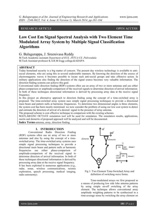
Fig 1: Two Element Time-Switched Array and
definition of switching wave forms.
Time-modulated arrays we first proposed as
a means of producing low side lobe antenna patterns
by using simple on-off switching of the array
element. The technique allows conventional array
amplitude weighting patterns to be synthesized in a
time-average sense by switching the array element on
RESEARCH ARTICLE OPEN ACCESS
2. G. Balagurappa et al Int. Journal of Engineering Research and Applications www.ijera.com
ISSN : 2248-9622, Vol. 4, Issue 3( Version 1), March 2014, pp.181-184
www.ijera.com 182 | P a g e
for a period that corresponds to the relative amplitude
weight of the array element.
An inherent problem normally associated
with time-modulated arrays is that they generate
unwanted harmonics, or sidebands, at multiples of the
switching frequency and most research into time-
modulated arrays has concentrated on minimizing or
controlling these harmonics [4]-[9]. More recently
work has been carried out to investigate the use of
phase centre motion to control side lobe levels [10]
and the application of time-modulated arrays in
Doppler radar.
In this contribution we describe a prototype
two element time-switched array system and present
measured data to illustrate the performance of the
array.
Direction of arrival
We have seen that there is a one-to-one
relationship between the direction of a signal and the
associated received steering vector. It should
therefore be possible to invert the relationship and
estimate the direction of a signal from the received
signals. An antenna array therefore should be able to
provide for direction of arrival estimation. We have
also seen that there is a Fourier relationship between
the beam pattern and the excitation at the array. This
allows the direction of arrival (DOA) estimation
problem to be treated as equivalent to spectral
estimation.
Fig 2: The DOA estimation problem
The problem set up is shown in Fig. 2.
Several (M) signals impinge on a linear, equispaced,
array with N elements, each with direction φi. The
goal of DOA estimation is to use the data received at
the array to estimate φi, i = 1, . . .M. It is generally
assumed that M < N, though there exist approaches
(such as maximum likelihood estimation) that do not
place this constraint.
II. SYSTEM DESCRIPTION
The time-switched array system is shown
schematically in Fig.1 and consists of two antenna
elements separated by a distance d. Each element is
assumed to exhibit an Omni directional radiation
pattern in the plane of the diagram. The output from
each element is connected to the array output via a
switch in the feed line; the element switching period
are also defined in Fg.1. A complete analysis of the
system may be found in [2] but for the purpose of this
contribution we will assume that the elements are
alternately switched on and off with an equal mark-
space ratio square wave switching function such that
= =
If we assume that the spacing between the
elements is a half wavelength, the output from the
array may be described [2] by
A (θ,t) = ,where
Fig 3: Details of the measurement set-up.
Hence the output of the array is phase
modulated and the depth of modulation is dependent
on the angle of arrival of the incident signal. For
illumination broadside to the array, the array output is
not modulated. However, as the illumination angle
increases the depth of modulation increases until at
end fire illumination (θ = 90deg and the array output
exhibits 270 deg phase shift modulation. A plot of the
array receive pattern at the illumination frequency,
, is given in Fig.2 and shows a directional
response with a peak on broadside and a null
response at The directional pattern occurs
because as the depth of phase modulation increases
energy is redistributed from the carrier into
sidebands, and at end fire there is zero energy at the
carrier frequency. If we now examine the output of
the time-switched array at the first harmonic.
Multiple Signal Classification Algorithms:
Of all techniques shown in Fig. 2, MUSIC is
probably the most popular technique. MUSIC, as are
many adaptive techniques, is dependent on the
correlation matrix of the data. Using the data model ,
3. G. Balagurappa et al Int. Journal of Engineering Research and Applications www.ijera.com
ISSN : 2248-9622, Vol. 4, Issue 3( Version 1), March 2014, pp.181-184
www.ijera.com 183 | P a g e
The matrix S is a N ×M matrix of the M
steering vectors. Assuming that the different signals
to be uncorrelated, the correlation matrix of x can be
written as
Where
The signal covariance matrix, Rs, is clearly
a N × N matrix with rank M. It therefore has N−M
eigenvectors corresponding to the zero eigenvalue.
Let qm be such an eigenvector. Therefore,
where this final equation is valid since the matrix A is
clearly positive definite. Equation (49) implies that
all N −M eigenvectors (qm) of Rs corresponding to
the zero eigenvalue are orthogonal. to all M signal
steering vectors. This is the basis for MUSIC. Call
Qn the N ×(N −M) matrix of these eigenvectors.
Note that since the eigenvectors making up
Qn are orthogonal to the signal steering vectors, the
denominator becomes zero when φ is a signal
direction.
Algorithm steps
Step1: Estimate the correlation matrix R using Eqn.
(54). Find its eigendecomposition R = QΛQH.
Step 2: Partition Q to obtain Qn, corresponding to the
(N − M) smallest eigenvalues of Q, which spans the
noise subspace.
Step 3: Plot, as a function of φ, the MUSIC function
PMUSIC (φ) in Eqn. (53).
Step 4: The M signal directions are the M largest
peaks of PMUSIC (φ).
The time-switched array was designed and
constructed to operate at 2400MHz using quarter-
wave monopoles as the two array elements. The
monopoles were constructed from 1.5 mm copper
wire mounted on a 200 mm diameter ground plane
using chassis mounting 3.5mm connectors. Because
the array was only required to operate with equal
mark-space ratio square-wave switching, a SPDT
switch was constructed based on a design provided
by Philips Semiconductors using BAP51-02 surface
mount PIN diodes. The switch was using constructed
using micro strip on standard FR4 circuit board. The
switch was mounted on the underside of the array
ground plane and connections were made to the
monopoles using connected to the monopoles using
short length of co-axial cable. However as the outputs
of the SPDT switch were not phase matched, a co-
axial line stretcher was inserted into one of the
monopole connections to allow phase compensation.
For ease of measurement the array was tested when
operating in transmit mode. The measurements were
made in an anechoic antenna test chamber using an
HP 8350B as the RF source and an Agilent E4407B
spectrum analyzer as a receiver.
Fig 4: Spectral Analysis using MUSIC Algorithm
0 50 100 150 200 250 300 350 400
-25
-20
-15
-10
-5
0
5
10
Output
Angle (deg)
Gain(dB)
Fig 5: Measured Angle of Arrival: 90,270
Antenna Arrays
An antenna Array is a configuration of
individual radiating elements that are arranged in
4. G. Balagurappa et al Int. Journal of Engineering Research and Applications www.ijera.com
ISSN : 2248-9622, Vol. 4, Issue 3( Version 1), March 2014, pp.181-184
www.ijera.com 184 | P a g e
space and can be used to produce a directional
radiation pattern Single-element antennas have
radiation patterns that are broad and hence have a low
directivity that is not suitable for long distance
communications.
A high directivity can be still be achieved by
increasing the electrical dimensions (in terms of
wavelength) and hence the physical size of the
antenna.
0.5
1
30
210
60
240
90
270
120
300
150
330
180 0
0.5
1
30
210
60
240
90
270
120
300
150
330
180 0
Fig 6: Array Factor and Array Element
The SPDT switch was modulated with a
square wave derived from a standard laboratory
signal generator at a frequency of 20 kHz. Fig. 3
shows the received spectrum measured broadside to
the array prior to phase compensation.
The spectrum contains a components at the
fundamental frequency (2400 MHz) and also
harmonic components at 20 kHz intervals due to the
fact that the outputs from the RF are not phase
matched. It is also evident that although the array was
modulated with an equal mark-space ratio switching
waveform, even harmonics are present in the
spectrum. However the even harmonics are at a low
level (more that 25 dB below the unmodulated
fundamental) and may be attributed to a combination
of many factors including a non-ideal switching
waveform and small differences in the amplitudes of
the signals radiating from the two monopoles. With
the array still orientated at broadside the line stretcher
was adjusted until the harmonics of the received
spectrum were minimized. With the array calibrated,
measurements of the received power levels were
recorded at the fundamental and the first harmonic
frequency over an angular range of +/-90 deg and 270
deg. To obtained from a simple model based on array
factor.
III. CONCLUSION
While in the presence of a two element time-
switched array system have been proposed. The
signals to each element of the array are time switched
to provide a phase modulated output signal in which
the depth of modulation is dependent on the angle of
arrival of the received signal. The angular response to
the array at the fundamental frequency of the
received signal exhibits a directional response at
broadside, while the response at the first harmonic of
the switching frequency exhibits a deep null.
REFERENCES
[1] M.J.Wilson and B.S.Halo, the ARRL
Handbook for the Radio mateur, 65th
ed.Washington, DC: American Radio Relay
League, 1988.
[2] A.Tennant and B.chambeers, “A two-element
time-modulated array with direction finding
properties,”IEEEE Antennas Wireless
propag. Lett, vol. 6, pp.64-65, 2007.
[3] A.Tennant and B.chambers “Direction
finding using a four element. Time-switched
array,” presented at the Loughborough
Antennas and propagation conf,
Loughborough, U, K, Mar.17-18, 2008.
[4] H.E.Shanks and R.W.Bckmoree,”Four-
dimensional electromagnetic radiators,
“canard J.phys, vol. 37, p.263, 1959.
[5] W.H. Kummel, A. T. Villenuve,T.S.Fong and
F.G. Terrio,”ultra- low side lobes from time-
modulated arrays”IEEE Trans Antennas
propag., vol. 11,pp.633-69,1963.
[6] S.Yang, Y.B.Gan,Z, and A.Qing,” Sideband
suppression in time-modulated linear arrays
by the differential evolution algorithm,”IEEE
Antennas Wireless Propag.Lett.,vol. 1,pp.
173-175,2002.
[7] S.Yang, Y.B.Gan, and P.k.Tan,”A new
technique for Power- pattern synthesis in
time-modulated linear arrays,”IEEE
Antennas Wireless propag. Lett, vol.3, p.298-
300, 2004.
[8] J.Fondevlia, J.c.Bregains, F.Ares, and
E.Moreno, ”Optimising uniformly excited
linear arrays thorough time
modulation,”IEEE Antennas Wireless
Propag.Lett, vol.3, .298-300, 2004.
[9] A. Tennant and B.Chambers, “Control of the
harmonic Radiation.
[10] S.Yang, Y.B. Gan, and P.K.Tan,”Linear
antenna array with bidirectional phase center
motion,” IEEE Trans.Antennas Propag.,
vol.53, No.5.1829-1835, May 2005.

![G. Balagurappa et al Int. Journal of Engineering Research and Applications www.ijera.com
ISSN : 2248-9622, Vol. 4, Issue 3( Version 1), March 2014, pp.181-184
www.ijera.com 182 | P a g e
for a period that corresponds to the relative amplitude
weight of the array element.
An inherent problem normally associated
with time-modulated arrays is that they generate
unwanted harmonics, or sidebands, at multiples of the
switching frequency and most research into time-
modulated arrays has concentrated on minimizing or
controlling these harmonics [4]-[9]. More recently
work has been carried out to investigate the use of
phase centre motion to control side lobe levels [10]
and the application of time-modulated arrays in
Doppler radar.
In this contribution we describe a prototype
two element time-switched array system and present
measured data to illustrate the performance of the
array.
Direction of arrival
We have seen that there is a one-to-one
relationship between the direction of a signal and the
associated received steering vector. It should
therefore be possible to invert the relationship and
estimate the direction of a signal from the received
signals. An antenna array therefore should be able to
provide for direction of arrival estimation. We have
also seen that there is a Fourier relationship between
the beam pattern and the excitation at the array. This
allows the direction of arrival (DOA) estimation
problem to be treated as equivalent to spectral
estimation.
Fig 2: The DOA estimation problem
The problem set up is shown in Fig. 2.
Several (M) signals impinge on a linear, equispaced,
array with N elements, each with direction φi. The
goal of DOA estimation is to use the data received at
the array to estimate φi, i = 1, . . .M. It is generally
assumed that M < N, though there exist approaches
(such as maximum likelihood estimation) that do not
place this constraint.
II. SYSTEM DESCRIPTION
The time-switched array system is shown
schematically in Fig.1 and consists of two antenna
elements separated by a distance d. Each element is
assumed to exhibit an Omni directional radiation
pattern in the plane of the diagram. The output from
each element is connected to the array output via a
switch in the feed line; the element switching period
are also defined in Fg.1. A complete analysis of the
system may be found in [2] but for the purpose of this
contribution we will assume that the elements are
alternately switched on and off with an equal mark-
space ratio square wave switching function such that
= =
If we assume that the spacing between the
elements is a half wavelength, the output from the
array may be described [2] by
A (θ,t) = ,where
Fig 3: Details of the measurement set-up.
Hence the output of the array is phase
modulated and the depth of modulation is dependent
on the angle of arrival of the incident signal. For
illumination broadside to the array, the array output is
not modulated. However, as the illumination angle
increases the depth of modulation increases until at
end fire illumination (θ = 90deg and the array output
exhibits 270 deg phase shift modulation. A plot of the
array receive pattern at the illumination frequency,
, is given in Fig.2 and shows a directional
response with a peak on broadside and a null
response at The directional pattern occurs
because as the depth of phase modulation increases
energy is redistributed from the carrier into
sidebands, and at end fire there is zero energy at the
carrier frequency. If we now examine the output of
the time-switched array at the first harmonic.
Multiple Signal Classification Algorithms:
Of all techniques shown in Fig. 2, MUSIC is
probably the most popular technique. MUSIC, as are
many adaptive techniques, is dependent on the
correlation matrix of the data. Using the data model ,](data:image/gif;base64,R0lGODlhAQABAIAAAAAAAP///yH5BAEAAAAALAAAAAABAAEAAAIBRAA7)