Prepared by :
Lalit Chavda(u15ee056)
Veeresh Vannala(u15ee057)
Purushottam Kumar(u15ee058)
Rakesh Raju(u15ee059)
Tejaswi Prasad(u15ee60)
TYPES OF ALTERNATOR & ITS
APPLICATION
S.V.N.I.T. Surat
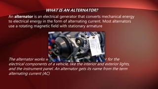
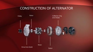
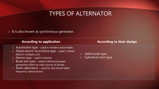
An alternator is an electrical generator that converts mechanical energy
to electrical energy in the form of alternating current. Most alternators
use a rotating magnetic field with stationary armature
The alternator works with the battery to generate power for the
electrical components of a vehicle, like the interior and exterior lights,
and the instrument panel. An alternator gets its name from the term
alternating current (AC)
CONSTRUCTION OF ALTERNATOR
Pulley
Drive End shield
Rotor
Collector-ring
end Shield
Rotor
Stator
TYPES OF ALTERNATOR
:- It is also known as synchronous generator.
According to application According to their design
o Automotive type - used in modern automobile.
o Diesel electric locomotive type - used in diesel
electric multiple unit.
o Marine type - used in marine.
o Brush less type - used in electrical power
generation plant as main source of power.
o Radio alternators - used for low brand radio
frequency transmission.
o Salient pole type.
o Cylindrical rotor type.
Alternators can be also classified as :
Based on output power
1. Single Phase
2. Three Phase
Based on the working principle
1. Revolving armature type
2. Revolving field type
Based on the speed on rotation
1. Turbo alternator
2. Low speed alternator
Based on coiling
1. Air cooling
2. Hydrogen cooling
• Salient means sticking out or projected out. A
salient pole is a magnetic pole that is projected
out of the rotor surface.
• The salient pole alternators are slow-speed
machines, speed varying from 150 to 600 rpm.
These alternators are driven by hydraulic
turbines. They are also called water-wheel
generators or hydro-generators
• Salient type rotor has non-uniform air-gap and
two or four poles
• Salient-pole construction can not be made strong
enough to withstand the mechanical stress at
higher speeds
Salient pole type
• Cylindrical rotor is non-projecting surface type
• Cylindrical rotor type rotor has small diameter
and large length
• Cylindrical rotor type rotor is used for high speed
and has uniform air-gap
• Cylindrical rotors have four or more poles
• High speed alternators (1500 – 3000 rpm) are
driven by steam turbines and use non-salient
type rotors due to following reason :
– Gives noiseless operation at high speeds
– Flux is uniformly distributed along the periphery, so proper
sine wave is obtained which gives better emf
Cylindrical rotor type
• A single phase alternator has a stator made up of a
number of windings in series, forming a single
circuit in which an output voltage is generated.
• Figure illustrates a schematic diagram of a single
phase alternator having four poles. The stator has
four polar groups evenly spaced around the stator
frame. The rotor has four poles, with adjacent poles
of opposite polarity.
• As the rotor revolves, ac voltages are induced in
the stator windings. Since one rotor pole is in the
same position relative to a stator winding as any
other rotor pole, all stator polar groups are cut by
equal numbers of magnetic lines of force at any
time.
SINGLE PHASE ALTERNATOR
• Two Phase Alternator:
• Two phase alternators have two or more single phase windings
spaced symmetrically around the stator. In a two phase alternator
there are two single phase windings spaced physically so that the
ac voltage induced in one is 90° out of phase with the voltage
induced in the other. The windings are electrically separate from
each other. When one winding is being cut by maximum flux, the
other is being cut by no flux. This condition establishes a 90°
relation between the two phases.
• Three Phase Alternator :
• A three phase, or polyphase circuit, is used in most aircraft
alternators, instead of a single or two phase alternator. The three
phase alternator has three single phase windings spaced so that
the voltage induced in each winding is 120° out of phase with
• the voltages in the other two windings. A
• schematic diagram of a three phase stator showing all the coils
becomes complex and difficult to see what is actually happening.
• A brushless alternator is composed of two alternators
built end-to-end on one shaft. Smaller brushless
alternators may look like one unit but the two parts are
readily identifiable on the large versions. The larger of
the two sections is the main alternator and the smaller
one is the exciter. The exciter has stationary field coils
and a rotating armature (power coils).
• The main alternator uses the opposite configuration with
a rotating field and stationary armature. A bridge
rectifier, called the rotating rectifier assembly, is
mounted on a plate attached to the rotor. Neither
brushes nor slip rings are used, which reduces the
number of wearing parts.
BRUSHLESS ALTERNATOR
• Turbo Alternators are alternators coupled to
turbines. Turbo alternators run at high speeds and
develop large quantities of power usually of the
order of hundreds of Megawatts.
• The rotor of the Turbo alternator is usually made of
many pieces connected together. Turbo generators
usually have cylindrical rotors. The speed of the
rotor is around 3000 rpm (50 Hz) or 3600 (60 Hz).
• Turbo alternators are extremely sensitive machines
as they operate at very high speed.
• They are typically used where emergency and
standby power is needed
• Smaller turbo-generators with gas turbines are
often used as auxiliary power units.
TURBO ALTERNATOR
REVOLVING ARMATURE TYPE ALTERNATOR
• The rotating armature alternator is essentially a
loop rotating through a stationarymagnetic
fealties cutting action of the loop through the
magnetic field generates ac in the loop.
• This ac isremoved from the loop by means of
slip rings and applied to an external load.
• The rotating field alternator has a
stationary armature and a rotating field.
Highvoltages can be generated in the
armature and applied to the load directly,
without the need of slip ringsand
brushes.
• The low dc voltage is applied to the
rotor field by means of slip rings, but this
does notintroduce any insulation
problems.
REVOLVING FIELD TYPE ALTERNATOR
• Electric generators:
Most power generation stations use
synchronous machines as their
generators. Connection of these
generators to the utility grid requires
synchronization conditions to be
met.
SPECIFIC APPLICATION:
• Automative Alternators:
Alternators are used in modern automobiles to
charge the battery and to power the electrical
system when its engine is running.
Until the 1960s, automobiles used
DC dynamo generators with commutators. With
the availability of affordable silicon
diode rectifiers, alternators were used instead
• Diesel Electric Locomotive Alternator:
In later diesel electric locomotives and diesel electric multiple units, the prime mover turns an
alternator which provides electricity for the traction motors (AC or DC).
The traction alternator usually incorporates integral silicon diode rectifiers to provide the
traction motors with up to 1200 volts DC (DC traction, which is used directly) or the common
inverter bus (AC traction, which is first inverted from dc to three-phase ac).
The first diesel electric locomotives, and many of those still in service, use DC generators as,
before silicon power electronics, it was easier to control the speed of DC traction motors. Most
of these had two generators: one to generate the excitation current for a larger main
generator.
• Marine Alternators:
Marine alternators used in yachts are similar to
automotive alternators, with appropriate
adaptations to the salt-water environment. Marine
alternators are designed to be explosion proof so
that brush sparking will not ignite explosive gas
mixtures in an engine room environment. They may
be 12 or 24 volt depending on the type of system
installed. Larger marine diesels may have two or
more alternators to cope with the heavy electrical
demand of a modern yacht. On single alternator
circuits, the power may be split between the engine
starting battery and the domestic or house battery
(or batteries) by use of a split-charge diode (battery
isolator) or a voltage-sensitive relay.
• Radio Alternators:
High frequency alternators of the variable-reluctance
type were applied commercially to radio transmission in
the low-frequency radio bands. These were used for
transmission of Morse code and, experimentally, for
transmission of voice and music. In the Alexanderson
alternator, both the field winding and armature winding
are stationary, and current is induced in the armature by
virtue of the changing magnetic reluctance of the rotor
(which has no windings or current carrying parts). Such
machines were made to produce radio frequency
current for radio transmissions, although the efficiency
was low.
Thank You

types of alternator & its application

  • 1.
    Prepared by : LalitChavda(u15ee056) Veeresh Vannala(u15ee057) Purushottam Kumar(u15ee058) Rakesh Raju(u15ee059) Tejaswi Prasad(u15ee60) TYPES OF ALTERNATOR & ITS APPLICATION S.V.N.I.T. Surat
  • 2.
    An alternator isan electrical generator that converts mechanical energy to electrical energy in the form of alternating current. Most alternators use a rotating magnetic field with stationary armature The alternator works with the battery to generate power for the electrical components of a vehicle, like the interior and exterior lights, and the instrument panel. An alternator gets its name from the term alternating current (AC)
  • 3.
    CONSTRUCTION OF ALTERNATOR Pulley DriveEnd shield Rotor Collector-ring end Shield Rotor Stator
  • 4.
    TYPES OF ALTERNATOR :-It is also known as synchronous generator. According to application According to their design o Automotive type - used in modern automobile. o Diesel electric locomotive type - used in diesel electric multiple unit. o Marine type - used in marine. o Brush less type - used in electrical power generation plant as main source of power. o Radio alternators - used for low brand radio frequency transmission. o Salient pole type. o Cylindrical rotor type.
  • 5.
    Alternators can bealso classified as : Based on output power 1. Single Phase 2. Three Phase Based on the working principle 1. Revolving armature type 2. Revolving field type Based on the speed on rotation 1. Turbo alternator 2. Low speed alternator Based on coiling 1. Air cooling 2. Hydrogen cooling
  • 6.
    • Salient meanssticking out or projected out. A salient pole is a magnetic pole that is projected out of the rotor surface. • The salient pole alternators are slow-speed machines, speed varying from 150 to 600 rpm. These alternators are driven by hydraulic turbines. They are also called water-wheel generators or hydro-generators • Salient type rotor has non-uniform air-gap and two or four poles • Salient-pole construction can not be made strong enough to withstand the mechanical stress at higher speeds Salient pole type
  • 7.
    • Cylindrical rotoris non-projecting surface type • Cylindrical rotor type rotor has small diameter and large length • Cylindrical rotor type rotor is used for high speed and has uniform air-gap • Cylindrical rotors have four or more poles • High speed alternators (1500 – 3000 rpm) are driven by steam turbines and use non-salient type rotors due to following reason : – Gives noiseless operation at high speeds – Flux is uniformly distributed along the periphery, so proper sine wave is obtained which gives better emf Cylindrical rotor type
  • 8.
    • A singlephase alternator has a stator made up of a number of windings in series, forming a single circuit in which an output voltage is generated. • Figure illustrates a schematic diagram of a single phase alternator having four poles. The stator has four polar groups evenly spaced around the stator frame. The rotor has four poles, with adjacent poles of opposite polarity. • As the rotor revolves, ac voltages are induced in the stator windings. Since one rotor pole is in the same position relative to a stator winding as any other rotor pole, all stator polar groups are cut by equal numbers of magnetic lines of force at any time. SINGLE PHASE ALTERNATOR
  • 9.
    • Two PhaseAlternator: • Two phase alternators have two or more single phase windings spaced symmetrically around the stator. In a two phase alternator there are two single phase windings spaced physically so that the ac voltage induced in one is 90° out of phase with the voltage induced in the other. The windings are electrically separate from each other. When one winding is being cut by maximum flux, the other is being cut by no flux. This condition establishes a 90° relation between the two phases. • Three Phase Alternator : • A three phase, or polyphase circuit, is used in most aircraft alternators, instead of a single or two phase alternator. The three phase alternator has three single phase windings spaced so that the voltage induced in each winding is 120° out of phase with • the voltages in the other two windings. A • schematic diagram of a three phase stator showing all the coils becomes complex and difficult to see what is actually happening.
  • 10.
    • A brushlessalternator is composed of two alternators built end-to-end on one shaft. Smaller brushless alternators may look like one unit but the two parts are readily identifiable on the large versions. The larger of the two sections is the main alternator and the smaller one is the exciter. The exciter has stationary field coils and a rotating armature (power coils). • The main alternator uses the opposite configuration with a rotating field and stationary armature. A bridge rectifier, called the rotating rectifier assembly, is mounted on a plate attached to the rotor. Neither brushes nor slip rings are used, which reduces the number of wearing parts. BRUSHLESS ALTERNATOR
  • 11.
    • Turbo Alternatorsare alternators coupled to turbines. Turbo alternators run at high speeds and develop large quantities of power usually of the order of hundreds of Megawatts. • The rotor of the Turbo alternator is usually made of many pieces connected together. Turbo generators usually have cylindrical rotors. The speed of the rotor is around 3000 rpm (50 Hz) or 3600 (60 Hz). • Turbo alternators are extremely sensitive machines as they operate at very high speed. • They are typically used where emergency and standby power is needed • Smaller turbo-generators with gas turbines are often used as auxiliary power units. TURBO ALTERNATOR
  • 12.
    REVOLVING ARMATURE TYPEALTERNATOR • The rotating armature alternator is essentially a loop rotating through a stationarymagnetic fealties cutting action of the loop through the magnetic field generates ac in the loop. • This ac isremoved from the loop by means of slip rings and applied to an external load.
  • 13.
    • The rotatingfield alternator has a stationary armature and a rotating field. Highvoltages can be generated in the armature and applied to the load directly, without the need of slip ringsand brushes. • The low dc voltage is applied to the rotor field by means of slip rings, but this does notintroduce any insulation problems. REVOLVING FIELD TYPE ALTERNATOR
  • 14.
    • Electric generators: Mostpower generation stations use synchronous machines as their generators. Connection of these generators to the utility grid requires synchronization conditions to be met. SPECIFIC APPLICATION:
  • 15.
    • Automative Alternators: Alternatorsare used in modern automobiles to charge the battery and to power the electrical system when its engine is running. Until the 1960s, automobiles used DC dynamo generators with commutators. With the availability of affordable silicon diode rectifiers, alternators were used instead
  • 16.
    • Diesel ElectricLocomotive Alternator: In later diesel electric locomotives and diesel electric multiple units, the prime mover turns an alternator which provides electricity for the traction motors (AC or DC). The traction alternator usually incorporates integral silicon diode rectifiers to provide the traction motors with up to 1200 volts DC (DC traction, which is used directly) or the common inverter bus (AC traction, which is first inverted from dc to three-phase ac). The first diesel electric locomotives, and many of those still in service, use DC generators as, before silicon power electronics, it was easier to control the speed of DC traction motors. Most of these had two generators: one to generate the excitation current for a larger main generator.
  • 17.
    • Marine Alternators: Marinealternators used in yachts are similar to automotive alternators, with appropriate adaptations to the salt-water environment. Marine alternators are designed to be explosion proof so that brush sparking will not ignite explosive gas mixtures in an engine room environment. They may be 12 or 24 volt depending on the type of system installed. Larger marine diesels may have two or more alternators to cope with the heavy electrical demand of a modern yacht. On single alternator circuits, the power may be split between the engine starting battery and the domestic or house battery (or batteries) by use of a split-charge diode (battery isolator) or a voltage-sensitive relay.
  • 18.
    • Radio Alternators: Highfrequency alternators of the variable-reluctance type were applied commercially to radio transmission in the low-frequency radio bands. These were used for transmission of Morse code and, experimentally, for transmission of voice and music. In the Alexanderson alternator, both the field winding and armature winding are stationary, and current is induced in the armature by virtue of the changing magnetic reluctance of the rotor (which has no windings or current carrying parts). Such machines were made to produce radio frequency current for radio transmissions, although the efficiency was low.
  • 19.