Download to read offline
![2. 0 Literature Survey
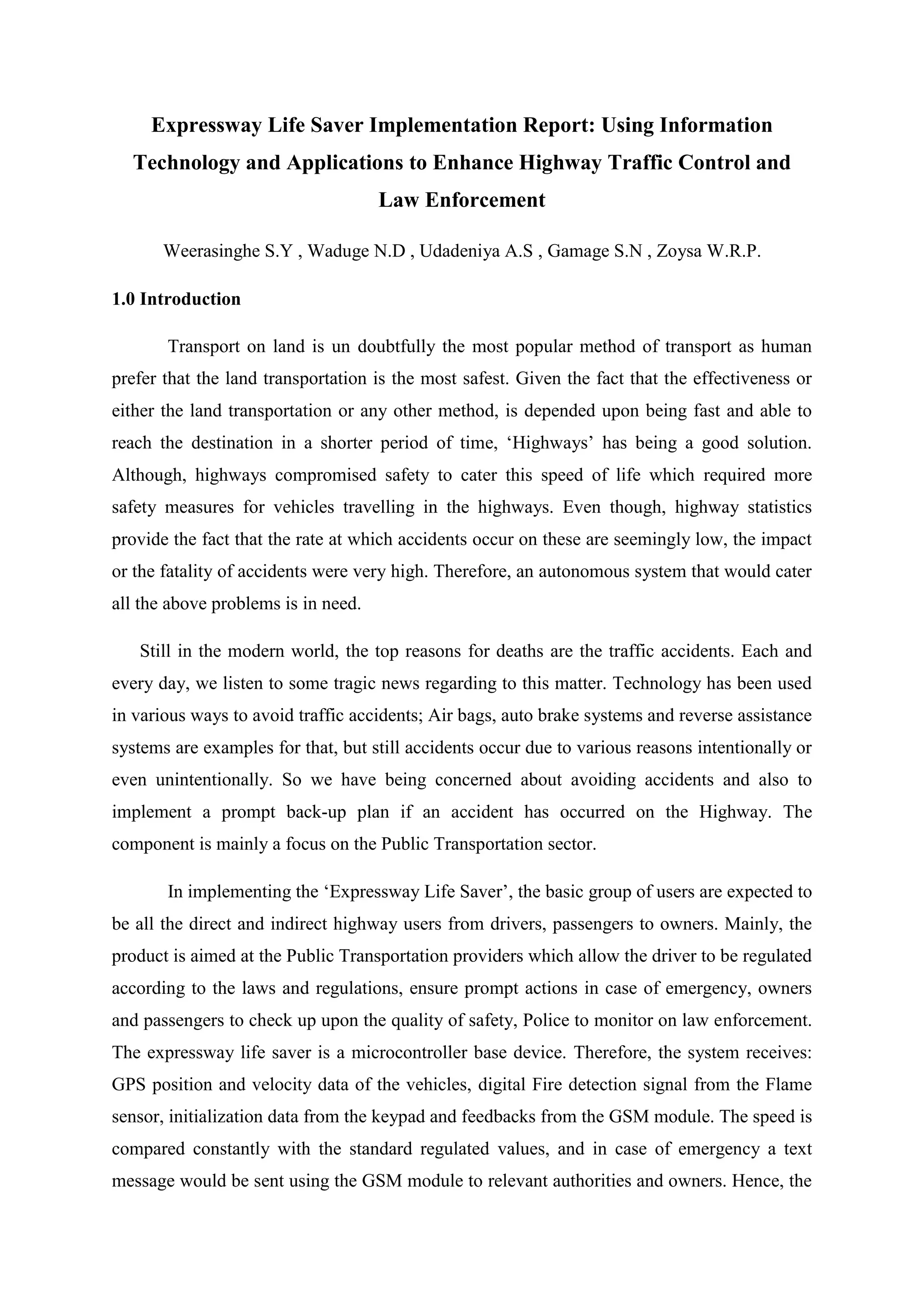
Expressway Monitoring and Advisory System
Expressway Monitoring and Advisory System or EMAS, was system developed by
the Singapore Technologies and Electronics in 1996 as a contact for the Singapore’s Land
Transport Authority. The system enables the LTA personnel to detect accidents and respond
to them quickly while notifying the driver of adverse traffic conditions and safety
instructions.
The EMAS was implemented as system that consists of cameras and LED sign
boards. The cameras transmit data to a central location and the staffs monitor the traffic and
the staff reacts in case of emergency. In such cases, the drivers are informed of the hazards
through the Sign boards. This system is already implemented in Sri Lanka’s highways as
well. [2]
Figure 2.1 : Current EMAS system in most highways
Traffic Cameras and Number Plate Readers
A traffic enforcement camera (also red light camera, road safety camera, road
rule camera, photo radar, photo enforcement, speed camera, Gatso, safety camera, bus
lane camera, Safe-T-Cam, depending on use) is a camera which may be mounted beside or
over a road or installed in an enforcement vehicle to detect traffic regulation violations,
including speeding, vehicles going through a red traffic light, unauthorized use of a bus lane,
or for recording vehicles inside a congestion charge area. It may be linked to an automated
ticketing system.](https://image.slidesharecdn.com/expresswaylifesaverimplementationreport-170525183504/75/Expressway-Life-Saver-Implementation-Report-5-2048.jpg)
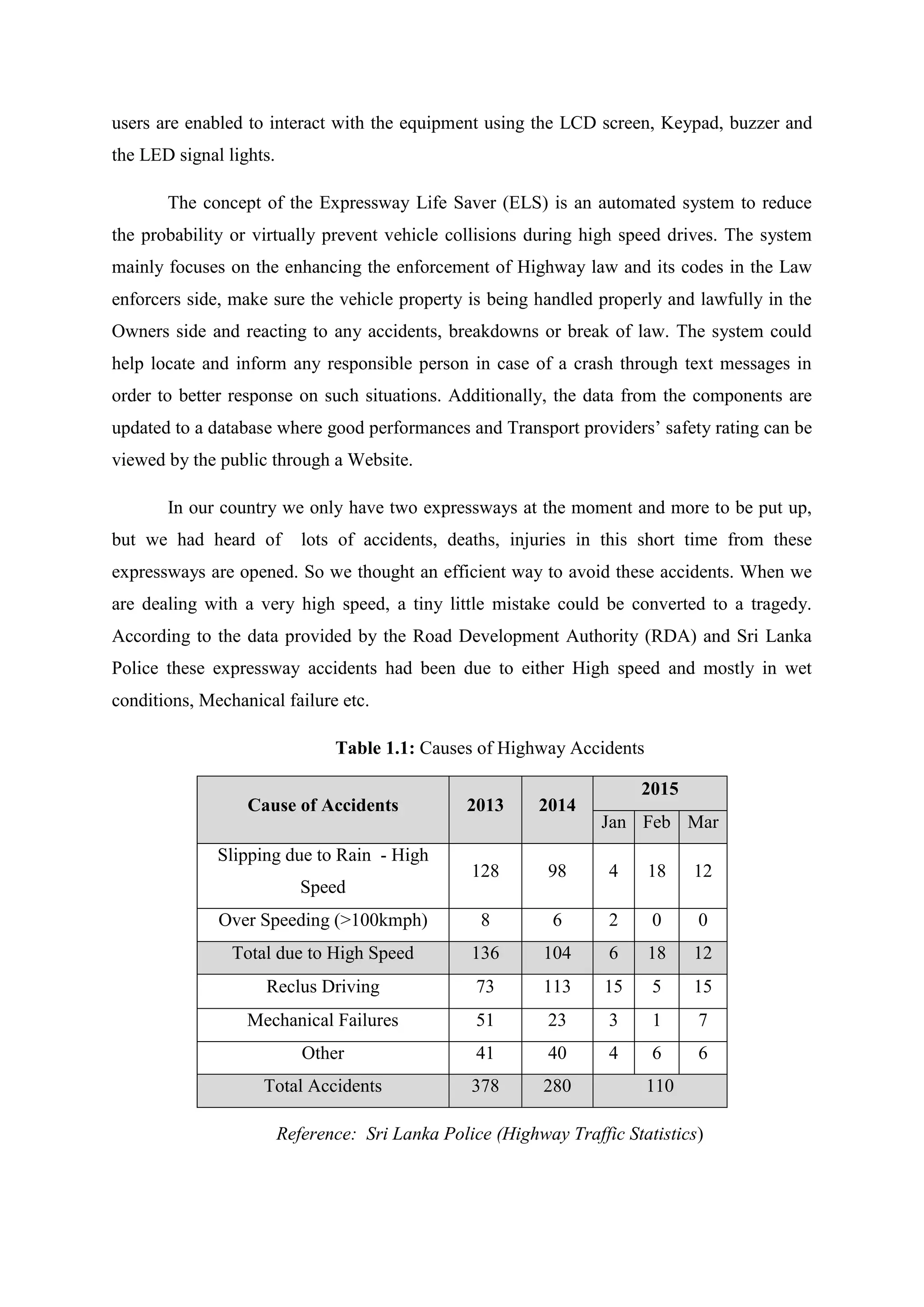
![The latest automatic number plate recognition systems can be used for the detection
of average speeds and raise concerns over loss of privacy and the potential for governments
to establish mass surveillance of vehicle movements and therefore by association also the
movement of the vehicle’s owner. Vehicles owners are often required by law to identify the
driver of the vehicle and a case was taken to the European Court of Human Rights which
found that human rights were not being breached. Some groups, such as the National
Motorists Association in the USA, claim that systems “encourage … revenue-driven
enforcement” rather than the declared objectives. [1]
Therefore, the traffic cameras have its own inherent problems. Therefore, the problem
of interfering privacy could be addressed by the proposed system by using a GPS tracker
instead of a visual media. This also enables to tack the vehicle’s performances real time since
the cameras are only capable of making a contribution to law enforcement at places where
they exists.
Hence, the case of being specific to one kind (Eg: Bus lane traffic camera) has lessen
the scope of the traffic cameras. This provide the fact that the officials and local governments
who have used these systems would have had to duplicate the cost for similar devices for the
same purpose but different in operation. Therefore, the investment would have being high as
it comes with an installation cost. Thus, the concept of ELS not being vehicle has the
advantage of catering the safety requirement for any vehicle which doesn’t have an
installation cost as well since the device is designed to be mobile and compact.
Highway Performance monitoring using GPS
Embedded sensors such as “loop detectors” and radar/laser speed detectors are placed
in (loop detector) or alongside of (radar/laser speed detector) the pavement to detect the
presence and speed of each vehicle traveling by that specific location. The advantage of
these systems is that they measure the speed of essentially every vehicle passing by that
location. This produces an enormous volume of speed data that effectively characterize the
temporal distribution of speed by time-of day, day-of-week, weather and even some incidents
such as police action, construction and accidents.](https://image.slidesharecdn.com/expresswaylifesaverimplementationreport-170525183504/75/Expressway-Life-Saver-Implementation-Report-6-2048.jpg)
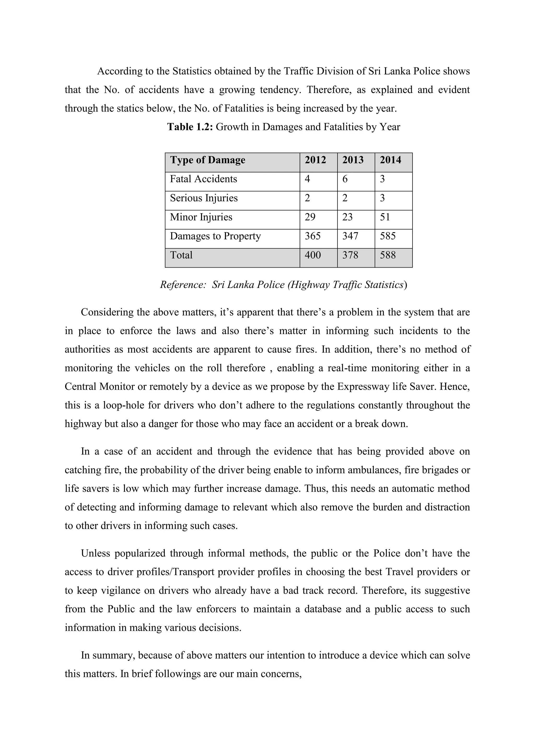
![The disadvantage is that this speed information is available only at the locations
where there existed both the foresight to monitor that specific location and the substantial
infrastructure funding that these systems require.[3]
40 of the above systems do prevail in Sri Lanka as well. These also have the same
problems as of the Traffic cameras and those mentioned in the text above as well. Another
disadvantage would be the effectiveness of these systems in severe weather conditions as
heavy rain etc. could create lot of noise in the system as these are exposed to the outside
environment. Thus, static charges generating from thunder and lightning also creates a danger
to the systems existence. Therefore, the systems are often offline in severe weather when they
are actually required.
Highway Rescue System
This system was developed by a Sri Lankan school student in 2015 in order to provide
prompt communication between the distressed vehicle and an emergency authority. Further
details of the implementation haven’t been provided.
Expressway Monitoring System
The expressway monitoring system was developed recently by the Computer Science
and Engineering Department of University of Moratuwa. The system is known to have used
cameras for image processing and adopted Artificial intelligence, Robotics technologies
according to the sources.](https://image.slidesharecdn.com/expresswaylifesaverimplementationreport-170525183504/75/Expressway-Life-Saver-Implementation-Report-7-2048.jpg)
![7.0 REFERENCES
[1]en.wikipedia.org/wiki/Traffic_enforcement_camera
[2]en.wikipedia.org/wiki/Expressway_Monitoring_and_Advisory_System
[3]Kornhauser, Alain L Ph. D., Highway Performance Monitoring Using GPS:
Characterization of Travel Speeds on any Roadway Segment, pp3
[4]www.adaderana.lk/news/29196/eight-injured-in-e01-expressway-crash
[5]www.police.lk/index.php/traffic-statistics
[6]www.police.lk/index.php/traffic-statistics/112
[7]www.police.lk/index.php/traffic-statistics/113
[8]www.sundaytimes.lk/130505/uploads/Southern-Expressway-accidents.jpg](https://image.slidesharecdn.com/expresswaylifesaverimplementationreport-170525183504/75/Expressway-Life-Saver-Implementation-Report-22-2048.jpg)

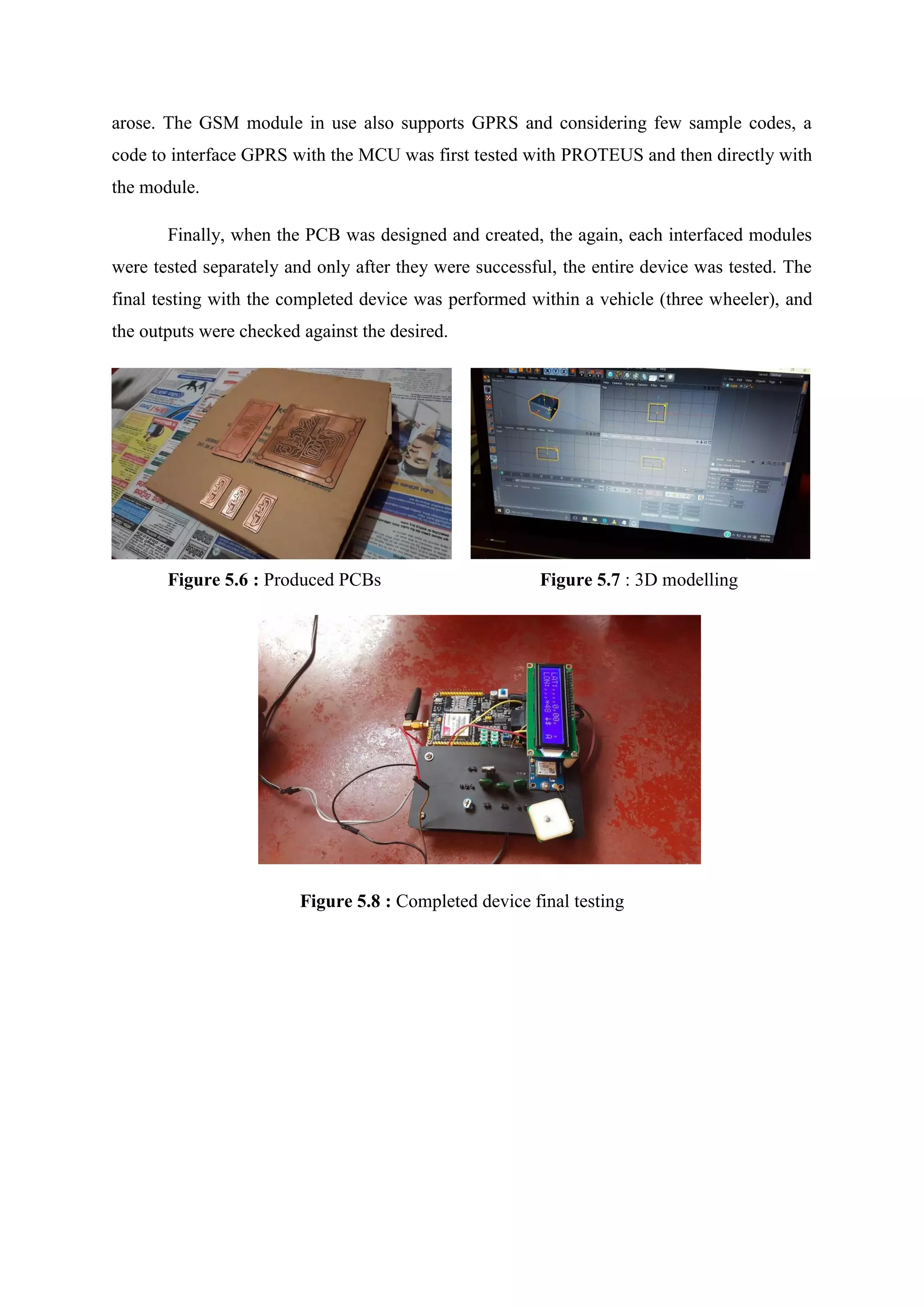
The 'Expressway Life Saver' implementation report details a microcontroller-based system designed to enhance highway safety by monitoring vehicle speed, detecting emergencies, and reporting incidents to authorities via GPS and GSM technology. This system aims to mitigate traffic accidents and improve law enforcement by maintaining a database of driver profiles and vehicle conditions accessible to the public. By streamlining communication during emergencies and encouraging compliance with traffic laws, the project seeks to create safer highways for all users.
![[Zulfadli] automated enforcement system](https://cdn.slidesharecdn.com/ss_thumbnails/zulfadliautomatedenforcementsystem-121205111343-phpapp01-thumbnail.jpg?width=640&height=640&fit=bounds)


