SlideShare a Scribd company logo
1 of 19
Download to read offline
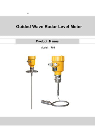
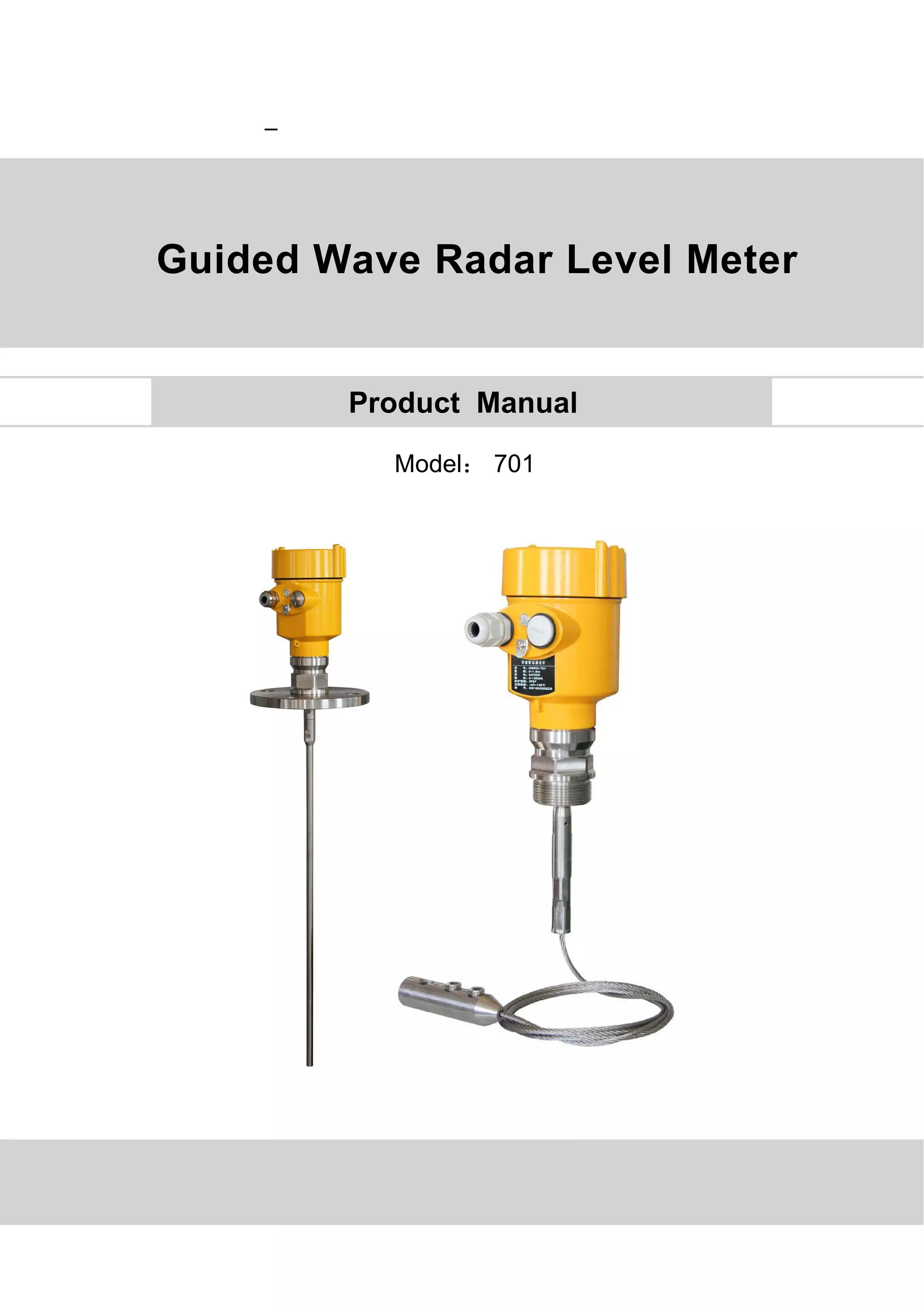
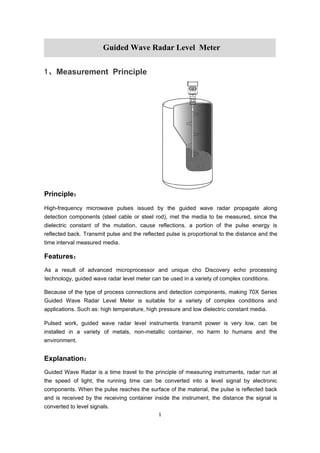
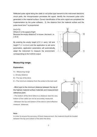
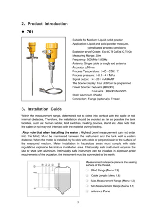
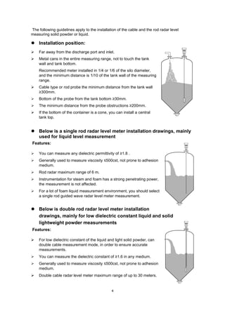
-
Model: 701
Guided Wave Radar Level Meter
Product Manual
Directory
1、Product Overview...............................................................................1
2、Product Introduction....................................................................3
3、The Installation Requirements........................................................3
4、Structure Size................................................................................8
5、The Electrical Connection..................................................................8
6、Adjustment Instructions.............................................................11
7、Technical Parameters...........................................................13
8、Product Selection & Ordering Information.....................................16
Material level meter selection parameter table......................17
1
1、Measurement Principle
Principle:
High-frequency microwave pulses issued by the guided wave radar propagate along
detection components (steel cable or steel rod), met the media to be measured, since the
dielectric constant of the mutation, cause reflections, a portion of the pulse energy is
reflected back. Transmit pulse and the reflected pulse is proportional to the distance and the
time interval measured media.
Features:
As a result of advanced microprocessor and unique cho Discovery echo processing
technology, guided wave radar level meter can be used in a variety of complex conditions.
Because of the type of process connections and detection components, making 70X Series
Guided Wave Radar Level Meter is suitable for a variety of complex conditions and
applications. Such as: high temperature, high pressure and low dielectric constant media.
Pulsed work, guided wave radar level instruments transmit power is very low, can be
installed in a variety of metals, non-metallic container, no harm to humans and the
environment.
Explanation:
Guided Wave Radar is a time travel to the principle of measuring instruments, radar run at
the speed of light, the running time can be converted into a level signal by electronic
components. When the pulse reaches the surface of the material, the pulse is reflected back
and is received by the receiving container inside the instrument, the distance the signal is
converted to level signals.
Guided Wave Radar Level Meter
2
Reflected pulse signal along the cable or rod probe type transmit to the instrument electronic
circuit parts, the microprocessor processes the signal, identify the microwave pulse echo
generated in the material surface. Correct identification of the echo signal are completed the
implementation by the pulse software , D, the distance from the material surface and the
pulse travel time T is proportional:
D=C×T/2
Where C is the speed of light
Because the empty distance E is known, the level L is:
L=E-D
By entering the empty height of E (= zero), full tank
height F (= hundred) and the application to set some
parameters, application parameters will automatically
adapt the instrument to measure the environment,
corresponding to the 4-20mA output.
Measuring range:
Explanation:
H--- Measuring range
L---Empty distance
B---The top of the blind
E---The minimum distance from the probe to the tank wall
--Blind spot is the minimum distance between the top of
the highest material surface materials and measurement
reference point.
--The bottom of the blind refers to a distance near the very
bottom of the cable can not be accurately measured.
--Between the top and bottom of the blind is blind effective
measure distances.
Note:
In order to ensure the accuracy of level measurement, the material should be located
between the top and bottom of the blind the blind.
3
2、Product Introduction
 701
Suitable for Medium: Liquid, solid powder
Application: Liquid and solid powder measure,
complicated process conditions
Explosion-proof Grade: Exia IIC T6 Ga/Exd IIC T6 Gb
Measuring Range: 30m
Frequency: 500MHz-1.8GHz
Antenna: Single cable or single rod antenna
Accuracy: ±10mm
Process Temperature:(-40~250)℃
Process pressure:(-0.1~4)MPa
Signal output:(4~20)mA/HART
The Scene Display: Four LCD/Can be programmed
Power Source: Two-wire (DC24V)
Four-wire(DC24V/AC220V)
Shell: Aluminum /Plastic
Connection: Flange (optional) / Thread
3、Installation Guide
Within the measurement range, determined not to come into contact with the cable or rod
internal obstacles, Therefore, the installation should be avoided as far as possible the tank
facilities, such as: human ladder, limit switches, heating devices, stand etc. Also note that
the cable or rod may not intersect with the material during feeding.
Also note that when installing the meter : Highest Level measurement can not enter
into the blind; Must be maintained between the instrument and the tank wall a certain
distance; When the meter is installed, try to stick with cable or perpendicular to the surface of
the measured medium. Meter installation in hazardous areas must comply with state
regulations explosion hazardous installation area. Intrinsically safe instrument requires the
use of shell with aluminum. Intrinsically safe instrument can be installed in explosion-proof
requirements of the occasion, the instrument must be connected to the earth.
Measurement reference plane is the sealing
surface of the thread.
1 Blind Range (Menu 1.9)
2 Cable Length (Menu 1.8)
3 Max.Measurement Range (Menu 1.2)
4 Min.Measurement Range (Menu 1.1)
5 reference Plane
4
The following guidelines apply to the installation of the cable and the rod radar level
measuring solid powder or liquid.
 Installation position:
 Far away from the discharge port and inlet.
 Metal cans in the entire measuring range, not to touch the tank
wall and tank bottom.
Recommended meter installed in 1/4 or 1/6 of the silo diameter,
and the minimum distance is 1/10 of the tank wall of the measuring
range.
 Cable type or rod probe the minimum distance from the tank wall
≥300mm.
 Bottom of the probe from the tank bottom ≥30mm.
 The minimum distance from the probe obstructions ≥200mm.
 If the bottom of the container is a cone, you can install a central
tank top.
 Below is a single rod radar level meter installation drawings, mainly
used for liquid level measurement
Features:
 You can measure any dielectric permittivity of ≥1.8 .
 Generally used to measure viscosity ≤500cst, not prone to adhesion
medium.
 Rod radar maximum range of 6 m.
 Instrumentation for steam and foam has a strong penetrating power,
the measurement is not affected.
 For a lot of foam liquid measurement environment, you should select
a single rod guided wave radar level meter measurement.
 Below is double rod radar level meter installation
drawings, mainly for low dielectric constant liquid and solid
lightweight powder measurements
Features:
 For low dielectric constant of the liquid and light solid powder, can
double cable measurement mode, in order to ensure accurate
measurements.
 You can measure the dielectric constant of ≥1.6 in any medium.
 Generally used to measure viscosity ≤500cst, not prone to adhesion
medium.
 Double cable radar level meter maximum range of up to 30 meters.
5
 Installation Method:
 Reasonable meter installation to ensure long-term reliable and accurate
measurement
Guided Wave Radar Level Meter can be connected by threaded, thread length should not
exceed 15mm, also can be installed on a short tube. When installing a short tube diameter of
2 "to 6", the installation of a short tube height should ≤100mm ( Thread length and short
tube shorter measurement will be more stable), If you install a short pipe is longer, it is best
to cut it short, or using insulation bracket fixed cable type probe, avoiding probe in contact
with the short end of the pipe to further to affect the measurement.
 DN200 or DN250 installed in the short tube
When guided wave radar level meter need to be installed at the short pipe diameters greater
than 200mm, the short tube wall will produce an echo, the medium in the case of a low
dielectric constant can cause measurement errors. Therefore, with a diameter of 200mm or
250mm short tube, you need to choose a special flange with a "horn Interface" of.
6
 Installation Notes on plastic containers
Whether cable or rod type, if you want to guided wave radar is working properly, the process
of connecting to the metal surface should be. When the guided wave radar mounted on a
plastic pot, If the tank top is plastic or other non-conductive material, the instrument needs
with metal flanges, the use of threaded connections, to be equipped with a metal plate.
 Optimized interference
 Interference echo suppression : Software can be realized on disturbance echo
suppression, to achieve the desired measurement results.
 For a medium viscosity of less than 500cst, can bypass pipe or waveguide (Only for
liquids) to avoid interference.
 Installation of low dielectric constant of the liquid
For dielectric constant greater than 1.3, the viscosity ≤500cst, and is not easy adhesion
medium, guided wave radar meter can be installed in the waveguide is measured, has
the following characteristics:
 superior reliability, high-precision
 Can be used in any medium of dielectric constant ≥1.3, it doesn't matter between
measurement and conductive medium.
 obstructions and short pipe size does not affect the measurement
 Corrosive media measurement
If the measurement of corrosive media, the choice of rod or cable probe sets PTFE, PFA
sleeve measurement.
 installed in horizontal and vertical tank on tank
 Rod probe can be up to six meters, more than six meters for measuring distances tank,
the choice of 4mm rope probe.
 Installation and fixation with the same measurement of solid powder compartment.
7
 Distance from the tank wall ≥300mm, the probe must avoid contact with the tank wall.
 In the choice of probe length, note at the bottom of the probe from the tank bottom
distance> 30mm.
 If obstructions are more, or too close to the probe by the sensor, it can then be
measured by installing tube waveguide.
 The matters needing attention:
 To be measured in the waveguide radar, generally used in rod probe sensors, during
installation You should use insulated bracket fixed probe, ensuring rod probe with
concentric waveguide, or they will have a very strong false echoes.
 When measuring range exceeds the maximum measuring range rod probe should be
used in guided wave radar probe cable, In this case waveguide diameter should be
greater than or equal to 6 ", otherwise it will generate strong false echoes.
 Installation of right and wrong
 Moisture:
Wrong: Do not install the
meter above the feed
inlet stream, cable or rod
should avoid material
entrance.
Correct:
Note: when installed
outdoors take shade, rain
measures
For instruments installed
outdoors or indoors and
wet cooling or heating of
the tank, in order to
moisture, should tighten
the cable jacket, but also
to the cable at the inlet
bend downward,
as shown in Figure
8
4、Structure Size(Unit: mm)
5、The Electrical Connection
 Power Supply
(4~20) mA/HART(Two-wire)
Power supply and current signal are carried by the same two-wire
connection cable. See the Technical Specifications of this guide for
detailed requirement on power supply. A safety barrier should be placed
between power supply and instrument for intrinsically safe version.
(4~20) mA/HART(Four-wire)
Power supply and current signal are carried by two 2-wire connection
cables respectively. See the Technical Specifications of this guide for
detailed requirement on power supply.
Earth-connected current output can be used for standard version of level
instruments, while the explosion proof version must be operated with a
floating current output. Both instruments and earth terminals should be
connected with ground firmly and securely. Normally you can either choose
to connect with the earth terminal on vessel or adjacent ground in case of
plastic vessels.
9
 Cable Connection
General Introduction Supply cable can use ordinary two-core cable, the
cable diameter should be (5 ~ 9) mm, to ensure that
the cable entry seal. If electromagnetic interference
exists, recommended to use shielded cable.
(4~20) mA/HART(Two-wire) Supply cable can use ordinary two-core cable.
(4~20) mA/HART(Four-wire) Supply cable should be used with a dedicated ground
cable.
Shielding and wiring The two ends of shielded cable must be connected with
earth terminal. The shielded cable must be connected
with inner earth terminal directly inside the transducer,
while the outside earth terminal on housing must be
connected with ground. In the event of earth-connected
current, the shielding side of shielded cable must be
connected to ground potential via a ceramic capacitor
(e.g. 1nF/1500V) in order to dampen the low frequency
grounding current and avoid the disturbance caused by
high frequency signals.
 Wiring Diagram
24V 2-wire:
220V 4-wire:
10
 Explosion Proof Connection
The intrinsic safety version sensors (Exia IIc T6) use Alu-die casting housing and filling
Silicone rubber sealants internal structure aimed to prevent sparks resulted from circuit
failure from leaking out. It is applicable for the continuous level measurement of flammable
medium under Exia IIc T6.
A safety barrier FBS-2 must be used together with the intrinsic safety instrument. It is an
associated device to this product for the power supply of this product. The main specification
is intrinsic safety: Exia IIC, voltage of power supply: 24V DC ± 5%, short-circuit current:
135mA, operating current: 4...20mA.
All cables must be shielded. The max length is 500m for the cable from the barrier to the
sensor. Stray capacitor ≤ 0.1 μ F/Km, stray inductance 1mH/Km. Instrument must be
connected to the ground potential. Any unapproved associated device is not allowed to be
used.
Adjustment with HART Handheld Programmer
Explosion Proof Zone None-Explosion-Proof Zone
Choose one
Adjustment with SOFTware
Explosion Proof Zone None-Explosion-Proof Zone
Choose one
11
 Safety instructions:
 Please observe the local electrical code requirements!
 Please comply with local requirements for personnel health and safety regulations.
All electrical components of instrument operation must be completed by the formal
training of professionals.
 Please check the instrument nameplate to provide product specifications meet your
requirements. Please make sure that the power supply voltage and instrument
nameplate on the requirements.
 Protection Grade:
The instrument fully meet the requirements of protection class IP66/67, make sure the cable
head waterproof seal. As shown below:
 How to ensure that the installation meets IP67 requirements:
 Make sure that the sealing head is not damaged.
 Make sure that the cable is not damaged.
 Make sure the cable is used in line with the electrical connection specifications.
 Before entering the electrical interface, the cable is bent down wardly, to ensure that
water does not flow into the casing, see ①
 Please tighten the cable sealing head, see ②
 Keep electrical interface with blind unused block after block tight, see ③
6、Adjustment Instructions
 Adjustment Methods:
1 Display/adjustment module ViewPoint)
2 An adjustment software
3 HART handheld programmer
12
 Display / Adjustment Module
View Point is a display debugging tool that can be plugged in. The adjustment can be done
through operating with four buttons on View Point. Optional menu operation languages are
available for selection. View Point is only used for display after adjustment in that the
measurement results can be seen clearly through the glass window.
Display / Keypad
1 Liquid Crystal Display
2 Adjustment Keypad
 PC debugging
Connect with another unit
through HART
1 RS232ConnectCable/USBport
2 Radar level meter
3 HATR port adapter used
on COMWAY convertor
4 250 ohm Resistance
 HART Handheld Programmer
Adjust meter with HART
Handheld Programmer
1 HARTHandheld Programmer
2 Radar level meter
3 250 ohm Resistance
24 VDC
Power supply
Ω
24 VDC
Power supply
13
7、Technical Specification
General Parameters
Probe Material:
Rod Stainless Steel 316L/PTFE
Cable Stainless Steel 316L/PTFE
Coax Stainless Steel 316L/PTFE
Seal Viton fluororubber , Kalrez Fluorinated rubber
Process Connection Stainless Steel 316L
Shell Stainless Steel 316L, Plastic,Aluminum
Alu-die casting, Powder Coated
Seal ring between the
shell and the shell Silicone Rubber
View Point Window Polycarbonate
Ground Terminal Stainless Steel 316L
Power
2-Wire Standard Version (16~26)V DC
Intrinsic Safe Version (21.6~26.4)V DC
Power Consumption max. 22.5mA
Ripple Allowed
- <100Hz Uss < lV
- (100~100K)Hz Uss < l0mV
Flameproof Type
(22.8 ~ 26.4) V DC 2-wire system
(198 ~242)V AC 4-wire system / 110V AC 4-wire system
Power Consumption max. 1VA,1W
Parameters on Cable
Cable Entry/Plug Onecable entryof M20xl.5 (cablediameterof 5~9mm)
One blind stopper M20xl.5
SpringConnectionTerminal Applicable for cables with cross section of 2.5mm
Output
Output Signal (4~20)mA/HART
Resolution 1.6μA
Failure mode 20.5mA;22mA;3.9mA, hold
2-wire load resistance See the diagram below
4-wire load resistance Max.500 ohm
Integration Time ( 0~36)sec, adjustable
14
Technical data
Max Measurement Distance
701 30m/6m(Cable /Rod)
Measurement Interval About 1sec (Depend on parameter settings)
Adjustment Time About 1sec (Depend on parameter settings)
Resolution of Display 1mm
Accuracy ±10mm(See the accuracy illustration diagram below)
Temperature for Storage/Transport (-40~80) ℃
Process Temperature (Probe)
701 (-40~250)℃
Relative Humidity <95%
Pressure Max. 40MPa
Vibration Proof Mechanical vibration 10m/s² , (10~150)Hz
Max Pulling Force See the illustrative diagram on pulling force
The accuracy illustration diagram
15
When measuring solid medium, the pulling force is determined by the diameter of vessel and
medium level, some examples of pulling force generated by typical medium are shown on
the diagrams below.
16
8、Product Selection & Ordering Information
 701
Maximum Range / Type of detecting component
30000mm/ Single cable type or 6000mm / single rod type
Explosion Proof Approval
P Standard (Without Approval)
I Intrinsically Safe(Exia IIC T6 Ga)
G Flameproof (Exd IIC T6 Gb)
Type of detecting component /Material
A Cable Φ8mm / Stainless Steel 304
B Cable Φ4mm / Stainless Steel 316L
C Rod Φ10mm / Stainless Steel 304
D Rod Φ10mm / Stainless Steel 316L
Process Connection /Material
G Thread G1½″ A
N Thread 1½″ NPT
C Flange DN50 PN16C / Stainless Steel
D Flange DN80 PN16C / Stainless Steel
E Flange DN100 PN16C / Stainless Steel
F Flange DN150 PN16C / Stainless Steel
H Flange DN200 PN16C / Stainless Steel
I Flange 2〞150LBS ANSI Convex / Stainless Steel 316L
J Flange 3〞150LBS ANSI Convex / Stainless Steel 316L
K Flange 4〞150LBS ANSI Convex / Stainless Steel 316L
L Flange 6〞150LBS ANSI Convex / Stainless Steel 316L
M Flange 8〞150LBS ANSI Convex / Stainless Steel 316 L
Seal / Process Temperature
1. Normal (-40~130)℃
2. High Temperature (-40~250)℃
The Electronic Unit
3 (4~20) mA / 24V DC / HART two wire system
4 (4~20) mA / 220V AC / HART four wire system
5 RS485 Modbus / 6~24V four wire system
Outer Covering / Protection Class
L Aluminum / Single cavity / IP67
H Aluminum / Double cavity / IP67
G Plastic / Single cavity / IP65
K Stainless steel / Single cavity / IP67
Cable Line
M M 20 x 1.5
N ½″ NPT
Display / Programming
A With
X Without
17
Material level meter selection parameter table
Customer information
Company: Contact:
Address: Zip code:
The Telephone: Fax: Mobile phone:
E-mail: Date:
License
□The standard type (Non-explosion-proof) □ Intrinsically safe (Exia IIB T5)
□ Intrinsically safe (Exia IIC T6 Ga) □ Intrinsically safe+marine license (Exia IIC T6 Ga)
□ Intrinsically safe and Flame proof (Exd IIC T6 Gb)
Tank / Container Information
The Types of Tank:
□ Tank □ Reaction Tank □ Separation Tank □ Marine Tank
The Tank Structure:
Material of Tank: Pressure:
Tank size:
Tank Height: m Diameter:
The top of the tank:
□ Vault □ Flat □ Open □ Cone type
The bottom of the tank:
□ Cone bottom □ Flat □ Slope bottom □ Arc bottom
Installation:
□ Top installation □ Side installation
□ The bypass pipe mount □ Guided wave pipe installation
Installation takes over the top of the tank (information):
Height of take over : mm Diameter of take over :: mm
Measurement of Medium
Media name: □ Lliquid □ Solid □ Mixed Media
Medium temperature: ℃
Dielectric Constant:
Linked material: □ Yes □ No
Mixing: □ Yes □ No
Process Connection
Thread: □ G1½″ A □ 1½″ NPT
Flange □ Flange (DN= ) □ Flange (ANSI= )
Power supply:
□ 24V DC Two wire system □ 24V DC Four wire system □ 220V AC Four wire
system
Output: □ 4-20mA □ HART
Display: □ Take the meter display program □ Without meter display program

More Related Content

What's hot

What's hot (20)

Couple rod of locomotive
Couple rod of locomotiveCouple rod of locomotive
Couple rod of locomotive
 
thermocouple ppt
thermocouple pptthermocouple ppt
thermocouple ppt
 
analog and digital displays
analog and digital displaysanalog and digital displays
analog and digital displays
 
Four Bar Mechanism
Four Bar MechanismFour Bar Mechanism
Four Bar Mechanism
 
Bimetallic thermometer
Bimetallic thermometerBimetallic thermometer
Bimetallic thermometer
 
Frl Overview 0508
Frl Overview 0508Frl Overview 0508
Frl Overview 0508
 
Electromagnetic flow meter
Electromagnetic flow meterElectromagnetic flow meter
Electromagnetic flow meter
 
Steam distribution system, utilization and design
Steam distribution system, utilization and designSteam distribution system, utilization and design
Steam distribution system, utilization and design
 
Pressure Thermometer
Pressure ThermometerPressure Thermometer
Pressure Thermometer
 
Hydraulic actuators
Hydraulic actuatorsHydraulic actuators
Hydraulic actuators
 
Clamp or compression coupling
Clamp or compression couplingClamp or compression coupling
Clamp or compression coupling
 
various flow meter
various flow metervarious flow meter
various flow meter
 
Process control 2 chapter
Process control 2 chapterProcess control 2 chapter
Process control 2 chapter
 
Boiler drum's water level control
Boiler drum's water level controlBoiler drum's water level control
Boiler drum's water level control
 
Flow measurement part III
Flow measurement   part IIIFlow measurement   part III
Flow measurement part III
 
Steam turbines, Shankarappa K
Steam turbines, Shankarappa KSteam turbines, Shankarappa K
Steam turbines, Shankarappa K
 
Control system
Control systemControl system
Control system
 
elliptical Trammel micro-project report
elliptical Trammel micro-project reportelliptical Trammel micro-project report
elliptical Trammel micro-project report
 
coupling
couplingcoupling
coupling
 
presentation on dynamometers
presentation on dynamometerspresentation on dynamometers
presentation on dynamometers
 

Similar to Guided Wave Radar Level Meter.pdf

Mod mag m4000 datasheet badger meter electromagnetic flow meter_m-series
 Mod mag m4000 datasheet badger meter electromagnetic flow meter_m-series Mod mag m4000 datasheet badger meter electromagnetic flow meter_m-series
Mod mag m4000 datasheet badger meter electromagnetic flow meter_m-seriesENVIMART
 
Mod mag m3000 datasheet badger meter electromagnetic flow meter_m-series
 Mod mag m3000 datasheet badger meter electromagnetic flow meter_m-series Mod mag m3000 datasheet badger meter electromagnetic flow meter_m-series
Mod mag m3000 datasheet badger meter electromagnetic flow meter_m-seriesENVIMART
 
Vmi insertion type electromagnetic flow-meter instruction manual
Vmi insertion type electromagnetic flow-meter instruction manualVmi insertion type electromagnetic flow-meter instruction manual
Vmi insertion type electromagnetic flow-meter instruction manualPERAM RAVI
 
Edwards Signaling SD2W Installation Manual
Edwards Signaling SD2W Installation ManualEdwards Signaling SD2W Installation Manual
Edwards Signaling SD2W Installation ManualJMAC Supply
 
Ultrasonic Clamp On Insertion Flow Meter.pdf
Ultrasonic Clamp On Insertion Flow Meter.pdfUltrasonic Clamp On Insertion Flow Meter.pdf
Ultrasonic Clamp On Insertion Flow Meter.pdfManasMicrosystems
 
Dynasonics dxn datasheet badger meter portable clamp-on ultrasonic flow meter
Dynasonics dxn datasheet badger meter portable clamp-on ultrasonic flow meterDynasonics dxn datasheet badger meter portable clamp-on ultrasonic flow meter
Dynasonics dxn datasheet badger meter portable clamp-on ultrasonic flow meterENVIMART
 
Mod mag m5000 datasheet badger meter electromagnetic flow meter_m-series
 Mod mag m5000 datasheet badger meter electromagnetic flow meter_m-series Mod mag m5000 datasheet badger meter electromagnetic flow meter_m-series
Mod mag m5000 datasheet badger meter electromagnetic flow meter_m-seriesENVIMART
 
EasyTREK / EchoTREK Ultrasonic Level Transmitters for Liquids
EasyTREK / EchoTREK Ultrasonic Level Transmitters for LiquidsEasyTREK / EchoTREK Ultrasonic Level Transmitters for Liquids
EasyTREK / EchoTREK Ultrasonic Level Transmitters for LiquidsArjay Automation
 
Position Sensor SPS-L075-HALS
Position Sensor SPS-L075-HALSPosition Sensor SPS-L075-HALS
Position Sensor SPS-L075-HALSPremier Farnell
 
Ultrasonic level meter
Ultrasonic level meterUltrasonic level meter
Ultrasonic level meterhandson28
 

Similar to Guided Wave Radar Level Meter.pdf (20)

High frequency radar level meter zero902
High frequency radar  level meter zero902High frequency radar  level meter zero902
High frequency radar level meter zero902
 
Mod mag m4000 datasheet badger meter electromagnetic flow meter_m-series
 Mod mag m4000 datasheet badger meter electromagnetic flow meter_m-series Mod mag m4000 datasheet badger meter electromagnetic flow meter_m-series
Mod mag m4000 datasheet badger meter electromagnetic flow meter_m-series
 
Magnetic Flowmeter Selection Model Zero Instrument.pdf
Magnetic Flowmeter Selection Model Zero Instrument.pdfMagnetic Flowmeter Selection Model Zero Instrument.pdf
Magnetic Flowmeter Selection Model Zero Instrument.pdf
 
Mod mag m3000 datasheet badger meter electromagnetic flow meter_m-series
 Mod mag m3000 datasheet badger meter electromagnetic flow meter_m-series Mod mag m3000 datasheet badger meter electromagnetic flow meter_m-series
Mod mag m3000 datasheet badger meter electromagnetic flow meter_m-series
 
80G FM Radar Level Meter Product Manual
80G FM Radar Level Meter Product Manual80G FM Radar Level Meter Product Manual
80G FM Radar Level Meter Product Manual
 
Vmi insertion type electromagnetic flow-meter instruction manual
Vmi insertion type electromagnetic flow-meter instruction manualVmi insertion type electromagnetic flow-meter instruction manual
Vmi insertion type electromagnetic flow-meter instruction manual
 
ZERO100L ultrasonic level meter manual. two lines
ZERO100L ultrasonic level meter manual. two linesZERO100L ultrasonic level meter manual. two lines
ZERO100L ultrasonic level meter manual. two lines
 
ZERO100l ultrasonic level meter manual. two lines.0 3m
ZERO100l ultrasonic level meter manual. two lines.0 3mZERO100l ultrasonic level meter manual. two lines.0 3m
ZERO100l ultrasonic level meter manual. two lines.0 3m
 
Siemens Air velocity sensor
Siemens Air velocity sensorSiemens Air velocity sensor
Siemens Air velocity sensor
 
Radar Non-Contact Level Transmitter
Radar Non-Contact Level TransmitterRadar Non-Contact Level Transmitter
Radar Non-Contact Level Transmitter
 
Edwards Signaling SD2W Installation Manual
Edwards Signaling SD2W Installation ManualEdwards Signaling SD2W Installation Manual
Edwards Signaling SD2W Installation Manual
 
Innovations 2014
Innovations 2014Innovations 2014
Innovations 2014
 
Ultrasonic Clamp On Insertion Flow Meter.pdf
Ultrasonic Clamp On Insertion Flow Meter.pdfUltrasonic Clamp On Insertion Flow Meter.pdf
Ultrasonic Clamp On Insertion Flow Meter.pdf
 
Dynasonics dxn datasheet badger meter portable clamp-on ultrasonic flow meter
Dynasonics dxn datasheet badger meter portable clamp-on ultrasonic flow meterDynasonics dxn datasheet badger meter portable clamp-on ultrasonic flow meter
Dynasonics dxn datasheet badger meter portable clamp-on ultrasonic flow meter
 
Mod mag m5000 datasheet badger meter electromagnetic flow meter_m-series
 Mod mag m5000 datasheet badger meter electromagnetic flow meter_m-series Mod mag m5000 datasheet badger meter electromagnetic flow meter_m-series
Mod mag m5000 datasheet badger meter electromagnetic flow meter_m-series
 
EasyTREK / EchoTREK Ultrasonic Level Transmitters for Liquids
EasyTREK / EchoTREK Ultrasonic Level Transmitters for LiquidsEasyTREK / EchoTREK Ultrasonic Level Transmitters for Liquids
EasyTREK / EchoTREK Ultrasonic Level Transmitters for Liquids
 
Position Sensor SPS-L075-HALS
Position Sensor SPS-L075-HALSPosition Sensor SPS-L075-HALS
Position Sensor SPS-L075-HALS
 
Ultrasonic level meter
Ultrasonic level meterUltrasonic level meter
Ultrasonic level meter
 
Sensor data of ultrasonic flow meter
Sensor data of ultrasonic flow meterSensor data of ultrasonic flow meter
Sensor data of ultrasonic flow meter
 
Elcometer holiday detector
Elcometer holiday detectorElcometer holiday detector
Elcometer holiday detector
 

More from Dalian Zero Instrument Technology Co., Ltd China

More from Dalian Zero Instrument Technology Co., Ltd China (20)

An Article To Read And Understand The Radar Level Meter Antenna Knowledge
An Article To Read And Understand The Radar Level Meter Antenna KnowledgeAn Article To Read And Understand The Radar Level Meter Antenna Knowledge
An Article To Read And Understand The Radar Level Meter Antenna Knowledge
 
Analysis Of The Application Of Radar Level Meter In The Level Measurement Of ...
Analysis Of The Application Of Radar Level Meter In The Level Measurement Of ...Analysis Of The Application Of Radar Level Meter In The Level Measurement Of ...
Analysis Of The Application Of Radar Level Meter In The Level Measurement Of ...
 
Radar Level Meter Easily Measures Levels In Small Silos For Baking Ingredients
Radar Level Meter Easily Measures Levels In Small Silos For Baking IngredientsRadar Level Meter Easily Measures Levels In Small Silos For Baking Ingredients
Radar Level Meter Easily Measures Levels In Small Silos For Baking Ingredients
 
Radar Level Meter Brand Selection Guideline
Radar Level Meter Brand Selection GuidelineRadar Level Meter Brand Selection Guideline
Radar Level Meter Brand Selection Guideline
 
Application Of Guided Wave Radar Level Meter In Fuel Level Measurement In Shi...
Application Of Guided Wave Radar Level Meter In Fuel Level Measurement In Shi...Application Of Guided Wave Radar Level Meter In Fuel Level Measurement In Shi...
Application Of Guided Wave Radar Level Meter In Fuel Level Measurement In Shi...
 
Radar Level Gauges A Sharp Tool For Level Monitoring In Sulphur Pits
Radar Level Gauges A Sharp Tool For Level Monitoring In Sulphur PitsRadar Level Gauges A Sharp Tool For Level Monitoring In Sulphur Pits
Radar Level Gauges A Sharp Tool For Level Monitoring In Sulphur Pits
 
Radar Level Meter Selection And Application In Power Plants
Radar Level Meter Selection And Application In Power PlantsRadar Level Meter Selection And Application In Power Plants
Radar Level Meter Selection And Application In Power Plants
 
Application Of Guided Wave Radar Level Meter In The Level Measurement Of Amin...
Application Of Guided Wave Radar Level Meter In The Level Measurement Of Amin...Application Of Guided Wave Radar Level Meter In The Level Measurement Of Amin...
Application Of Guided Wave Radar Level Meter In The Level Measurement Of Amin...
 
How To Judge The Advantages And Disadvantages Of Radar Level Meter
How To Judge The Advantages And Disadvantages Of Radar Level MeterHow To Judge The Advantages And Disadvantages Of Radar Level Meter
How To Judge The Advantages And Disadvantages Of Radar Level Meter
 
A Brief Analysis Of Radar Level Meter Measuring Liquid Level In Leachate Wells
A Brief Analysis Of Radar Level Meter Measuring Liquid Level In Leachate WellsA Brief Analysis Of Radar Level Meter Measuring Liquid Level In Leachate Wells
A Brief Analysis Of Radar Level Meter Measuring Liquid Level In Leachate Wells
 
Application Of Radar Level Meter In Level Measurement Of Broken Glass Silo
Application Of Radar Level Meter In Level Measurement Of Broken Glass SiloApplication Of Radar Level Meter In Level Measurement Of Broken Glass Silo
Application Of Radar Level Meter In Level Measurement Of Broken Glass Silo
 
Misunderstandings In The Installation Of Radar Level Gauges
Misunderstandings In The Installation Of Radar Level GaugesMisunderstandings In The Installation Of Radar Level Gauges
Misunderstandings In The Installation Of Radar Level Gauges
 
Application Of Radar Level Meter In Liquid Level Measurement In Main Building...
Application Of Radar Level Meter In Liquid Level Measurement In Main Building...Application Of Radar Level Meter In Liquid Level Measurement In Main Building...
Application Of Radar Level Meter In Liquid Level Measurement In Main Building...
 
Application Of Radar Level Meter In Material Level Measurement Of Raw Materia...
Application Of Radar Level Meter In Material Level Measurement Of Raw Materia...Application Of Radar Level Meter In Material Level Measurement Of Raw Materia...
Application Of Radar Level Meter In Material Level Measurement Of Raw Materia...
 
How To Deal With Radar Level Gauge Distortion
How To Deal With Radar Level Gauge DistortionHow To Deal With Radar Level Gauge Distortion
How To Deal With Radar Level Gauge Distortion
 
Why Does The Transmitter Use 4-20mA Why Choose 4-20mA Instead Of 0-20mA
Why Does The Transmitter Use 4-20mA Why Choose 4-20mA Instead Of 0-20mAWhy Does The Transmitter Use 4-20mA Why Choose 4-20mA Instead Of 0-20mA
Why Does The Transmitter Use 4-20mA Why Choose 4-20mA Instead Of 0-20mA
 
How To Eliminate Interference Encountered By Radar Level Gauges
How To Eliminate Interference Encountered By Radar Level GaugesHow To Eliminate Interference Encountered By Radar Level Gauges
How To Eliminate Interference Encountered By Radar Level Gauges
 
Can Radar Level Gauge Measure Small Biogas Pools.doc
Can Radar Level Gauge Measure Small Biogas Pools.docCan Radar Level Gauge Measure Small Biogas Pools.doc
Can Radar Level Gauge Measure Small Biogas Pools.doc
 
Global Market Trends in Coriolis Mass Flow Meter Technology
Global Market Trends in Coriolis Mass Flow Meter TechnologyGlobal Market Trends in Coriolis Mass Flow Meter Technology
Global Market Trends in Coriolis Mass Flow Meter Technology
 
Application Of Radar Level Gauge In Offshore Oil And Gas Extraction Industry
Application Of Radar Level Gauge In Offshore Oil And Gas Extraction IndustryApplication Of Radar Level Gauge In Offshore Oil And Gas Extraction Industry
Application Of Radar Level Gauge In Offshore Oil And Gas Extraction Industry
 

Recently uploaded

M.C Lodges -- Guest House in Jhang.
M.C Lodges --  Guest House in Jhang.M.C Lodges --  Guest House in Jhang.
M.C Lodges -- Guest House in Jhang.Aaiza Hassan
 
Monte Carlo simulation : Simulation using MCSM
Monte Carlo simulation : Simulation using MCSMMonte Carlo simulation : Simulation using MCSM
Monte Carlo simulation : Simulation using MCSMRavindra Nath Shukla
 
Lean: From Theory to Practice — One City’s (and Library’s) Lean Story… Abridged
Lean: From Theory to Practice — One City’s (and Library’s) Lean Story… AbridgedLean: From Theory to Practice — One City’s (and Library’s) Lean Story… Abridged
Lean: From Theory to Practice — One City’s (and Library’s) Lean Story… AbridgedKaiNexus
 
VIP Call Girl Jamshedpur Aashi 8250192130 Independent Escort Service Jamshedpur
VIP Call Girl Jamshedpur Aashi 8250192130 Independent Escort Service JamshedpurVIP Call Girl Jamshedpur Aashi 8250192130 Independent Escort Service Jamshedpur
VIP Call Girl Jamshedpur Aashi 8250192130 Independent Escort Service JamshedpurSuhani Kapoor
 
Pitch Deck Teardown: NOQX's $200k Pre-seed deck
Pitch Deck Teardown: NOQX's $200k Pre-seed deckPitch Deck Teardown: NOQX's $200k Pre-seed deck
Pitch Deck Teardown: NOQX's $200k Pre-seed deckHajeJanKamps
 
Lowrate Call Girls In Sector 18 Noida ❤️8860477959 Escorts 100% Genuine Servi...
Lowrate Call Girls In Sector 18 Noida ❤️8860477959 Escorts 100% Genuine Servi...Lowrate Call Girls In Sector 18 Noida ❤️8860477959 Escorts 100% Genuine Servi...
Lowrate Call Girls In Sector 18 Noida ❤️8860477959 Escorts 100% Genuine Servi...lizamodels9
 
Call Girls In Sikandarpur Gurgaon ❤️8860477959_Russian 100% Genuine Escorts I...
Call Girls In Sikandarpur Gurgaon ❤️8860477959_Russian 100% Genuine Escorts I...Call Girls In Sikandarpur Gurgaon ❤️8860477959_Russian 100% Genuine Escorts I...
Call Girls In Sikandarpur Gurgaon ❤️8860477959_Russian 100% Genuine Escorts I...lizamodels9
 
Lowrate Call Girls In Laxmi Nagar Delhi ❤️8860477959 Escorts 100% Genuine Ser...
Lowrate Call Girls In Laxmi Nagar Delhi ❤️8860477959 Escorts 100% Genuine Ser...Lowrate Call Girls In Laxmi Nagar Delhi ❤️8860477959 Escorts 100% Genuine Ser...
Lowrate Call Girls In Laxmi Nagar Delhi ❤️8860477959 Escorts 100% Genuine Ser...lizamodels9
 
2024 Numerator Consumer Study of Cannabis Usage
2024 Numerator Consumer Study of Cannabis Usage2024 Numerator Consumer Study of Cannabis Usage
2024 Numerator Consumer Study of Cannabis UsageNeil Kimberley
 
Call Girls In Connaught Place Delhi ❤️88604**77959_Russian 100% Genuine Escor...
Call Girls In Connaught Place Delhi ❤️88604**77959_Russian 100% Genuine Escor...Call Girls In Connaught Place Delhi ❤️88604**77959_Russian 100% Genuine Escor...
Call Girls In Connaught Place Delhi ❤️88604**77959_Russian 100% Genuine Escor...lizamodels9
 
Catalogue ONG NUOC PPR DE NHAT .pdf
Catalogue ONG NUOC PPR DE NHAT      .pdfCatalogue ONG NUOC PPR DE NHAT      .pdf
Catalogue ONG NUOC PPR DE NHAT .pdfOrient Homes
 
Intro to BCG's Carbon Emissions Benchmark_vF.pdf
Intro to BCG's Carbon Emissions Benchmark_vF.pdfIntro to BCG's Carbon Emissions Benchmark_vF.pdf
Intro to BCG's Carbon Emissions Benchmark_vF.pdfpollardmorgan
 
GD Birla and his contribution in management
GD Birla and his contribution in managementGD Birla and his contribution in management
GD Birla and his contribution in managementchhavia330
 
Call Girls In Radisson Blu Hotel New Delhi Paschim Vihar ❤️8860477959 Escorts...
Call Girls In Radisson Blu Hotel New Delhi Paschim Vihar ❤️8860477959 Escorts...Call Girls In Radisson Blu Hotel New Delhi Paschim Vihar ❤️8860477959 Escorts...
Call Girls In Radisson Blu Hotel New Delhi Paschim Vihar ❤️8860477959 Escorts...lizamodels9
 
Sales & Marketing Alignment: How to Synergize for Success
Sales & Marketing Alignment: How to Synergize for SuccessSales & Marketing Alignment: How to Synergize for Success
Sales & Marketing Alignment: How to Synergize for SuccessAggregage
 
Lucknow 💋 Escorts in Lucknow - 450+ Call Girl Cash Payment 8923113531 Neha Th...
Lucknow 💋 Escorts in Lucknow - 450+ Call Girl Cash Payment 8923113531 Neha Th...Lucknow 💋 Escorts in Lucknow - 450+ Call Girl Cash Payment 8923113531 Neha Th...
Lucknow 💋 Escorts in Lucknow - 450+ Call Girl Cash Payment 8923113531 Neha Th...anilsa9823
 
Progress Report - Oracle Database Analyst Summit
Progress  Report - Oracle Database Analyst SummitProgress  Report - Oracle Database Analyst Summit
Progress Report - Oracle Database Analyst SummitHolger Mueller
 
Keppel Ltd. 1Q 2024 Business Update Presentation Slides
Keppel Ltd. 1Q 2024 Business Update  Presentation SlidesKeppel Ltd. 1Q 2024 Business Update  Presentation Slides
Keppel Ltd. 1Q 2024 Business Update Presentation SlidesKeppelCorporation
 

Recently uploaded (20)

M.C Lodges -- Guest House in Jhang.
M.C Lodges --  Guest House in Jhang.M.C Lodges --  Guest House in Jhang.
M.C Lodges -- Guest House in Jhang.
 
Monte Carlo simulation : Simulation using MCSM
Monte Carlo simulation : Simulation using MCSMMonte Carlo simulation : Simulation using MCSM
Monte Carlo simulation : Simulation using MCSM
 
Lean: From Theory to Practice — One City’s (and Library’s) Lean Story… Abridged
Lean: From Theory to Practice — One City’s (and Library’s) Lean Story… AbridgedLean: From Theory to Practice — One City’s (and Library’s) Lean Story… Abridged
Lean: From Theory to Practice — One City’s (and Library’s) Lean Story… Abridged
 
VIP Call Girl Jamshedpur Aashi 8250192130 Independent Escort Service Jamshedpur
VIP Call Girl Jamshedpur Aashi 8250192130 Independent Escort Service JamshedpurVIP Call Girl Jamshedpur Aashi 8250192130 Independent Escort Service Jamshedpur
VIP Call Girl Jamshedpur Aashi 8250192130 Independent Escort Service Jamshedpur
 
Pitch Deck Teardown: NOQX's $200k Pre-seed deck
Pitch Deck Teardown: NOQX's $200k Pre-seed deckPitch Deck Teardown: NOQX's $200k Pre-seed deck
Pitch Deck Teardown: NOQX's $200k Pre-seed deck
 
Lowrate Call Girls In Sector 18 Noida ❤️8860477959 Escorts 100% Genuine Servi...
Lowrate Call Girls In Sector 18 Noida ❤️8860477959 Escorts 100% Genuine Servi...Lowrate Call Girls In Sector 18 Noida ❤️8860477959 Escorts 100% Genuine Servi...
Lowrate Call Girls In Sector 18 Noida ❤️8860477959 Escorts 100% Genuine Servi...
 
Call Girls In Sikandarpur Gurgaon ❤️8860477959_Russian 100% Genuine Escorts I...
Call Girls In Sikandarpur Gurgaon ❤️8860477959_Russian 100% Genuine Escorts I...Call Girls In Sikandarpur Gurgaon ❤️8860477959_Russian 100% Genuine Escorts I...
Call Girls In Sikandarpur Gurgaon ❤️8860477959_Russian 100% Genuine Escorts I...
 
Lowrate Call Girls In Laxmi Nagar Delhi ❤️8860477959 Escorts 100% Genuine Ser...
Lowrate Call Girls In Laxmi Nagar Delhi ❤️8860477959 Escorts 100% Genuine Ser...Lowrate Call Girls In Laxmi Nagar Delhi ❤️8860477959 Escorts 100% Genuine Ser...
Lowrate Call Girls In Laxmi Nagar Delhi ❤️8860477959 Escorts 100% Genuine Ser...
 
2024 Numerator Consumer Study of Cannabis Usage
2024 Numerator Consumer Study of Cannabis Usage2024 Numerator Consumer Study of Cannabis Usage
2024 Numerator Consumer Study of Cannabis Usage
 
Call Girls In Connaught Place Delhi ❤️88604**77959_Russian 100% Genuine Escor...
Call Girls In Connaught Place Delhi ❤️88604**77959_Russian 100% Genuine Escor...Call Girls In Connaught Place Delhi ❤️88604**77959_Russian 100% Genuine Escor...
Call Girls In Connaught Place Delhi ❤️88604**77959_Russian 100% Genuine Escor...
 
Catalogue ONG NUOC PPR DE NHAT .pdf
Catalogue ONG NUOC PPR DE NHAT      .pdfCatalogue ONG NUOC PPR DE NHAT      .pdf
Catalogue ONG NUOC PPR DE NHAT .pdf
 
Intro to BCG's Carbon Emissions Benchmark_vF.pdf
Intro to BCG's Carbon Emissions Benchmark_vF.pdfIntro to BCG's Carbon Emissions Benchmark_vF.pdf
Intro to BCG's Carbon Emissions Benchmark_vF.pdf
 
GD Birla and his contribution in management
GD Birla and his contribution in managementGD Birla and his contribution in management
GD Birla and his contribution in management
 
Call Girls In Radisson Blu Hotel New Delhi Paschim Vihar ❤️8860477959 Escorts...
Call Girls In Radisson Blu Hotel New Delhi Paschim Vihar ❤️8860477959 Escorts...Call Girls In Radisson Blu Hotel New Delhi Paschim Vihar ❤️8860477959 Escorts...
Call Girls In Radisson Blu Hotel New Delhi Paschim Vihar ❤️8860477959 Escorts...
 
Sales & Marketing Alignment: How to Synergize for Success
Sales & Marketing Alignment: How to Synergize for SuccessSales & Marketing Alignment: How to Synergize for Success
Sales & Marketing Alignment: How to Synergize for Success
 
Lucknow 💋 Escorts in Lucknow - 450+ Call Girl Cash Payment 8923113531 Neha Th...
Lucknow 💋 Escorts in Lucknow - 450+ Call Girl Cash Payment 8923113531 Neha Th...Lucknow 💋 Escorts in Lucknow - 450+ Call Girl Cash Payment 8923113531 Neha Th...
Lucknow 💋 Escorts in Lucknow - 450+ Call Girl Cash Payment 8923113531 Neha Th...
 
Progress Report - Oracle Database Analyst Summit
Progress  Report - Oracle Database Analyst SummitProgress  Report - Oracle Database Analyst Summit
Progress Report - Oracle Database Analyst Summit
 
KestrelPro Flyer Japan IT Week 2024 (English)
KestrelPro Flyer Japan IT Week 2024 (English)KestrelPro Flyer Japan IT Week 2024 (English)
KestrelPro Flyer Japan IT Week 2024 (English)
 
Keppel Ltd. 1Q 2024 Business Update Presentation Slides
Keppel Ltd. 1Q 2024 Business Update  Presentation SlidesKeppel Ltd. 1Q 2024 Business Update  Presentation Slides
Keppel Ltd. 1Q 2024 Business Update Presentation Slides
 
Best Practices for Implementing an External Recruiting Partnership
Best Practices for Implementing an External Recruiting PartnershipBest Practices for Implementing an External Recruiting Partnership
Best Practices for Implementing an External Recruiting Partnership
 

Guided Wave Radar Level Meter.pdf

  • 1. - Model: 701 Guided Wave Radar Level Meter Product Manual
  • 2. Directory 1、Product Overview...............................................................................1 2、Product Introduction....................................................................3 3、The Installation Requirements........................................................3 4、Structure Size................................................................................8 5、The Electrical Connection..................................................................8 6、Adjustment Instructions.............................................................11 7、Technical Parameters...........................................................13 8、Product Selection & Ordering Information.....................................16 Material level meter selection parameter table......................17
  • 3. 1 1、Measurement Principle Principle: High-frequency microwave pulses issued by the guided wave radar propagate along detection components (steel cable or steel rod), met the media to be measured, since the dielectric constant of the mutation, cause reflections, a portion of the pulse energy is reflected back. Transmit pulse and the reflected pulse is proportional to the distance and the time interval measured media. Features: As a result of advanced microprocessor and unique cho Discovery echo processing technology, guided wave radar level meter can be used in a variety of complex conditions. Because of the type of process connections and detection components, making 70X Series Guided Wave Radar Level Meter is suitable for a variety of complex conditions and applications. Such as: high temperature, high pressure and low dielectric constant media. Pulsed work, guided wave radar level instruments transmit power is very low, can be installed in a variety of metals, non-metallic container, no harm to humans and the environment. Explanation: Guided Wave Radar is a time travel to the principle of measuring instruments, radar run at the speed of light, the running time can be converted into a level signal by electronic components. When the pulse reaches the surface of the material, the pulse is reflected back and is received by the receiving container inside the instrument, the distance the signal is converted to level signals. Guided Wave Radar Level Meter
  • 4. 2 Reflected pulse signal along the cable or rod probe type transmit to the instrument electronic circuit parts, the microprocessor processes the signal, identify the microwave pulse echo generated in the material surface. Correct identification of the echo signal are completed the implementation by the pulse software , D, the distance from the material surface and the pulse travel time T is proportional: D=C×T/2 Where C is the speed of light Because the empty distance E is known, the level L is: L=E-D By entering the empty height of E (= zero), full tank height F (= hundred) and the application to set some parameters, application parameters will automatically adapt the instrument to measure the environment, corresponding to the 4-20mA output. Measuring range: Explanation: H--- Measuring range L---Empty distance B---The top of the blind E---The minimum distance from the probe to the tank wall --Blind spot is the minimum distance between the top of the highest material surface materials and measurement reference point. --The bottom of the blind refers to a distance near the very bottom of the cable can not be accurately measured. --Between the top and bottom of the blind is blind effective measure distances. Note: In order to ensure the accuracy of level measurement, the material should be located between the top and bottom of the blind the blind.
  • 5. 3 2、Product Introduction  701 Suitable for Medium: Liquid, solid powder Application: Liquid and solid powder measure, complicated process conditions Explosion-proof Grade: Exia IIC T6 Ga/Exd IIC T6 Gb Measuring Range: 30m Frequency: 500MHz-1.8GHz Antenna: Single cable or single rod antenna Accuracy: ±10mm Process Temperature:(-40~250)℃ Process pressure:(-0.1~4)MPa Signal output:(4~20)mA/HART The Scene Display: Four LCD/Can be programmed Power Source: Two-wire (DC24V) Four-wire(DC24V/AC220V) Shell: Aluminum /Plastic Connection: Flange (optional) / Thread 3、Installation Guide Within the measurement range, determined not to come into contact with the cable or rod internal obstacles, Therefore, the installation should be avoided as far as possible the tank facilities, such as: human ladder, limit switches, heating devices, stand etc. Also note that the cable or rod may not intersect with the material during feeding. Also note that when installing the meter : Highest Level measurement can not enter into the blind; Must be maintained between the instrument and the tank wall a certain distance; When the meter is installed, try to stick with cable or perpendicular to the surface of the measured medium. Meter installation in hazardous areas must comply with state regulations explosion hazardous installation area. Intrinsically safe instrument requires the use of shell with aluminum. Intrinsically safe instrument can be installed in explosion-proof requirements of the occasion, the instrument must be connected to the earth. Measurement reference plane is the sealing surface of the thread. 1 Blind Range (Menu 1.9) 2 Cable Length (Menu 1.8) 3 Max.Measurement Range (Menu 1.2) 4 Min.Measurement Range (Menu 1.1) 5 reference Plane
  • 6. 4 The following guidelines apply to the installation of the cable and the rod radar level measuring solid powder or liquid.  Installation position:  Far away from the discharge port and inlet.  Metal cans in the entire measuring range, not to touch the tank wall and tank bottom. Recommended meter installed in 1/4 or 1/6 of the silo diameter, and the minimum distance is 1/10 of the tank wall of the measuring range.  Cable type or rod probe the minimum distance from the tank wall ≥300mm.  Bottom of the probe from the tank bottom ≥30mm.  The minimum distance from the probe obstructions ≥200mm.  If the bottom of the container is a cone, you can install a central tank top.  Below is a single rod radar level meter installation drawings, mainly used for liquid level measurement Features:  You can measure any dielectric permittivity of ≥1.8 .  Generally used to measure viscosity ≤500cst, not prone to adhesion medium.  Rod radar maximum range of 6 m.  Instrumentation for steam and foam has a strong penetrating power, the measurement is not affected.  For a lot of foam liquid measurement environment, you should select a single rod guided wave radar level meter measurement.  Below is double rod radar level meter installation drawings, mainly for low dielectric constant liquid and solid lightweight powder measurements Features:  For low dielectric constant of the liquid and light solid powder, can double cable measurement mode, in order to ensure accurate measurements.  You can measure the dielectric constant of ≥1.6 in any medium.  Generally used to measure viscosity ≤500cst, not prone to adhesion medium.  Double cable radar level meter maximum range of up to 30 meters.
  • 7. 5  Installation Method:  Reasonable meter installation to ensure long-term reliable and accurate measurement Guided Wave Radar Level Meter can be connected by threaded, thread length should not exceed 15mm, also can be installed on a short tube. When installing a short tube diameter of 2 "to 6", the installation of a short tube height should ≤100mm ( Thread length and short tube shorter measurement will be more stable), If you install a short pipe is longer, it is best to cut it short, or using insulation bracket fixed cable type probe, avoiding probe in contact with the short end of the pipe to further to affect the measurement.  DN200 or DN250 installed in the short tube When guided wave radar level meter need to be installed at the short pipe diameters greater than 200mm, the short tube wall will produce an echo, the medium in the case of a low dielectric constant can cause measurement errors. Therefore, with a diameter of 200mm or 250mm short tube, you need to choose a special flange with a "horn Interface" of.
  • 8. 6  Installation Notes on plastic containers Whether cable or rod type, if you want to guided wave radar is working properly, the process of connecting to the metal surface should be. When the guided wave radar mounted on a plastic pot, If the tank top is plastic or other non-conductive material, the instrument needs with metal flanges, the use of threaded connections, to be equipped with a metal plate.  Optimized interference  Interference echo suppression : Software can be realized on disturbance echo suppression, to achieve the desired measurement results.  For a medium viscosity of less than 500cst, can bypass pipe or waveguide (Only for liquids) to avoid interference.  Installation of low dielectric constant of the liquid For dielectric constant greater than 1.3, the viscosity ≤500cst, and is not easy adhesion medium, guided wave radar meter can be installed in the waveguide is measured, has the following characteristics:  superior reliability, high-precision  Can be used in any medium of dielectric constant ≥1.3, it doesn't matter between measurement and conductive medium.  obstructions and short pipe size does not affect the measurement  Corrosive media measurement If the measurement of corrosive media, the choice of rod or cable probe sets PTFE, PFA sleeve measurement.  installed in horizontal and vertical tank on tank  Rod probe can be up to six meters, more than six meters for measuring distances tank, the choice of 4mm rope probe.  Installation and fixation with the same measurement of solid powder compartment.
  • 9. 7  Distance from the tank wall ≥300mm, the probe must avoid contact with the tank wall.  In the choice of probe length, note at the bottom of the probe from the tank bottom distance> 30mm.  If obstructions are more, or too close to the probe by the sensor, it can then be measured by installing tube waveguide.  The matters needing attention:  To be measured in the waveguide radar, generally used in rod probe sensors, during installation You should use insulated bracket fixed probe, ensuring rod probe with concentric waveguide, or they will have a very strong false echoes.  When measuring range exceeds the maximum measuring range rod probe should be used in guided wave radar probe cable, In this case waveguide diameter should be greater than or equal to 6 ", otherwise it will generate strong false echoes.  Installation of right and wrong  Moisture: Wrong: Do not install the meter above the feed inlet stream, cable or rod should avoid material entrance. Correct: Note: when installed outdoors take shade, rain measures For instruments installed outdoors or indoors and wet cooling or heating of the tank, in order to moisture, should tighten the cable jacket, but also to the cable at the inlet bend downward, as shown in Figure
  • 10. 8 4、Structure Size(Unit: mm) 5、The Electrical Connection  Power Supply (4~20) mA/HART(Two-wire) Power supply and current signal are carried by the same two-wire connection cable. See the Technical Specifications of this guide for detailed requirement on power supply. A safety barrier should be placed between power supply and instrument for intrinsically safe version. (4~20) mA/HART(Four-wire) Power supply and current signal are carried by two 2-wire connection cables respectively. See the Technical Specifications of this guide for detailed requirement on power supply. Earth-connected current output can be used for standard version of level instruments, while the explosion proof version must be operated with a floating current output. Both instruments and earth terminals should be connected with ground firmly and securely. Normally you can either choose to connect with the earth terminal on vessel or adjacent ground in case of plastic vessels.
  • 11. 9  Cable Connection General Introduction Supply cable can use ordinary two-core cable, the cable diameter should be (5 ~ 9) mm, to ensure that the cable entry seal. If electromagnetic interference exists, recommended to use shielded cable. (4~20) mA/HART(Two-wire) Supply cable can use ordinary two-core cable. (4~20) mA/HART(Four-wire) Supply cable should be used with a dedicated ground cable. Shielding and wiring The two ends of shielded cable must be connected with earth terminal. The shielded cable must be connected with inner earth terminal directly inside the transducer, while the outside earth terminal on housing must be connected with ground. In the event of earth-connected current, the shielding side of shielded cable must be connected to ground potential via a ceramic capacitor (e.g. 1nF/1500V) in order to dampen the low frequency grounding current and avoid the disturbance caused by high frequency signals.  Wiring Diagram 24V 2-wire: 220V 4-wire:
  • 12. 10  Explosion Proof Connection The intrinsic safety version sensors (Exia IIc T6) use Alu-die casting housing and filling Silicone rubber sealants internal structure aimed to prevent sparks resulted from circuit failure from leaking out. It is applicable for the continuous level measurement of flammable medium under Exia IIc T6. A safety barrier FBS-2 must be used together with the intrinsic safety instrument. It is an associated device to this product for the power supply of this product. The main specification is intrinsic safety: Exia IIC, voltage of power supply: 24V DC ± 5%, short-circuit current: 135mA, operating current: 4...20mA. All cables must be shielded. The max length is 500m for the cable from the barrier to the sensor. Stray capacitor ≤ 0.1 μ F/Km, stray inductance 1mH/Km. Instrument must be connected to the ground potential. Any unapproved associated device is not allowed to be used. Adjustment with HART Handheld Programmer Explosion Proof Zone None-Explosion-Proof Zone Choose one Adjustment with SOFTware Explosion Proof Zone None-Explosion-Proof Zone Choose one
  • 13. 11  Safety instructions:  Please observe the local electrical code requirements!  Please comply with local requirements for personnel health and safety regulations. All electrical components of instrument operation must be completed by the formal training of professionals.  Please check the instrument nameplate to provide product specifications meet your requirements. Please make sure that the power supply voltage and instrument nameplate on the requirements.  Protection Grade: The instrument fully meet the requirements of protection class IP66/67, make sure the cable head waterproof seal. As shown below:  How to ensure that the installation meets IP67 requirements:  Make sure that the sealing head is not damaged.  Make sure that the cable is not damaged.  Make sure the cable is used in line with the electrical connection specifications.  Before entering the electrical interface, the cable is bent down wardly, to ensure that water does not flow into the casing, see ①  Please tighten the cable sealing head, see ②  Keep electrical interface with blind unused block after block tight, see ③ 6、Adjustment Instructions  Adjustment Methods: 1 Display/adjustment module ViewPoint) 2 An adjustment software 3 HART handheld programmer
  • 14. 12  Display / Adjustment Module View Point is a display debugging tool that can be plugged in. The adjustment can be done through operating with four buttons on View Point. Optional menu operation languages are available for selection. View Point is only used for display after adjustment in that the measurement results can be seen clearly through the glass window. Display / Keypad 1 Liquid Crystal Display 2 Adjustment Keypad  PC debugging Connect with another unit through HART 1 RS232ConnectCable/USBport 2 Radar level meter 3 HATR port adapter used on COMWAY convertor 4 250 ohm Resistance  HART Handheld Programmer Adjust meter with HART Handheld Programmer 1 HARTHandheld Programmer 2 Radar level meter 3 250 ohm Resistance 24 VDC Power supply Ω 24 VDC Power supply
  • 15. 13 7、Technical Specification General Parameters Probe Material: Rod Stainless Steel 316L/PTFE Cable Stainless Steel 316L/PTFE Coax Stainless Steel 316L/PTFE Seal Viton fluororubber , Kalrez Fluorinated rubber Process Connection Stainless Steel 316L Shell Stainless Steel 316L, Plastic,Aluminum Alu-die casting, Powder Coated Seal ring between the shell and the shell Silicone Rubber View Point Window Polycarbonate Ground Terminal Stainless Steel 316L Power 2-Wire Standard Version (16~26)V DC Intrinsic Safe Version (21.6~26.4)V DC Power Consumption max. 22.5mA Ripple Allowed - <100Hz Uss < lV - (100~100K)Hz Uss < l0mV Flameproof Type (22.8 ~ 26.4) V DC 2-wire system (198 ~242)V AC 4-wire system / 110V AC 4-wire system Power Consumption max. 1VA,1W Parameters on Cable Cable Entry/Plug Onecable entryof M20xl.5 (cablediameterof 5~9mm) One blind stopper M20xl.5 SpringConnectionTerminal Applicable for cables with cross section of 2.5mm Output Output Signal (4~20)mA/HART Resolution 1.6μA Failure mode 20.5mA;22mA;3.9mA, hold 2-wire load resistance See the diagram below 4-wire load resistance Max.500 ohm Integration Time ( 0~36)sec, adjustable
  • 16. 14 Technical data Max Measurement Distance 701 30m/6m(Cable /Rod) Measurement Interval About 1sec (Depend on parameter settings) Adjustment Time About 1sec (Depend on parameter settings) Resolution of Display 1mm Accuracy ±10mm(See the accuracy illustration diagram below) Temperature for Storage/Transport (-40~80) ℃ Process Temperature (Probe) 701 (-40~250)℃ Relative Humidity <95% Pressure Max. 40MPa Vibration Proof Mechanical vibration 10m/s² , (10~150)Hz Max Pulling Force See the illustrative diagram on pulling force The accuracy illustration diagram
  • 17. 15 When measuring solid medium, the pulling force is determined by the diameter of vessel and medium level, some examples of pulling force generated by typical medium are shown on the diagrams below.
  • 18. 16 8、Product Selection & Ordering Information  701 Maximum Range / Type of detecting component 30000mm/ Single cable type or 6000mm / single rod type Explosion Proof Approval P Standard (Without Approval) I Intrinsically Safe(Exia IIC T6 Ga) G Flameproof (Exd IIC T6 Gb) Type of detecting component /Material A Cable Φ8mm / Stainless Steel 304 B Cable Φ4mm / Stainless Steel 316L C Rod Φ10mm / Stainless Steel 304 D Rod Φ10mm / Stainless Steel 316L Process Connection /Material G Thread G1½″ A N Thread 1½″ NPT C Flange DN50 PN16C / Stainless Steel D Flange DN80 PN16C / Stainless Steel E Flange DN100 PN16C / Stainless Steel F Flange DN150 PN16C / Stainless Steel H Flange DN200 PN16C / Stainless Steel I Flange 2〞150LBS ANSI Convex / Stainless Steel 316L J Flange 3〞150LBS ANSI Convex / Stainless Steel 316L K Flange 4〞150LBS ANSI Convex / Stainless Steel 316L L Flange 6〞150LBS ANSI Convex / Stainless Steel 316L M Flange 8〞150LBS ANSI Convex / Stainless Steel 316 L Seal / Process Temperature 1. Normal (-40~130)℃ 2. High Temperature (-40~250)℃ The Electronic Unit 3 (4~20) mA / 24V DC / HART two wire system 4 (4~20) mA / 220V AC / HART four wire system 5 RS485 Modbus / 6~24V four wire system Outer Covering / Protection Class L Aluminum / Single cavity / IP67 H Aluminum / Double cavity / IP67 G Plastic / Single cavity / IP65 K Stainless steel / Single cavity / IP67 Cable Line M M 20 x 1.5 N ½″ NPT Display / Programming A With X Without
  • 19. 17 Material level meter selection parameter table Customer information Company: Contact: Address: Zip code: The Telephone: Fax: Mobile phone: E-mail: Date: License □The standard type (Non-explosion-proof) □ Intrinsically safe (Exia IIB T5) □ Intrinsically safe (Exia IIC T6 Ga) □ Intrinsically safe+marine license (Exia IIC T6 Ga) □ Intrinsically safe and Flame proof (Exd IIC T6 Gb) Tank / Container Information The Types of Tank: □ Tank □ Reaction Tank □ Separation Tank □ Marine Tank The Tank Structure: Material of Tank: Pressure: Tank size: Tank Height: m Diameter: The top of the tank: □ Vault □ Flat □ Open □ Cone type The bottom of the tank: □ Cone bottom □ Flat □ Slope bottom □ Arc bottom Installation: □ Top installation □ Side installation □ The bypass pipe mount □ Guided wave pipe installation Installation takes over the top of the tank (information): Height of take over : mm Diameter of take over :: mm Measurement of Medium Media name: □ Lliquid □ Solid □ Mixed Media Medium temperature: ℃ Dielectric Constant: Linked material: □ Yes □ No Mixing: □ Yes □ No Process Connection Thread: □ G1½″ A □ 1½″ NPT Flange □ Flange (DN= ) □ Flange (ANSI= ) Power supply: □ 24V DC Two wire system □ 24V DC Four wire system □ 220V AC Four wire system Output: □ 4-20mA □ HART Display: □ Take the meter display program □ Without meter display program