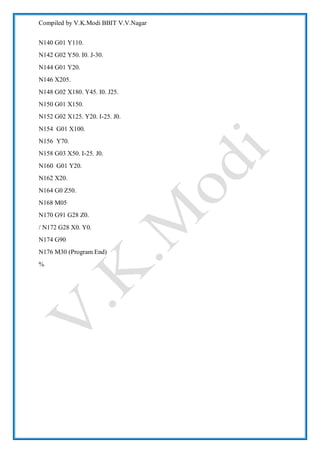
Download to read offline
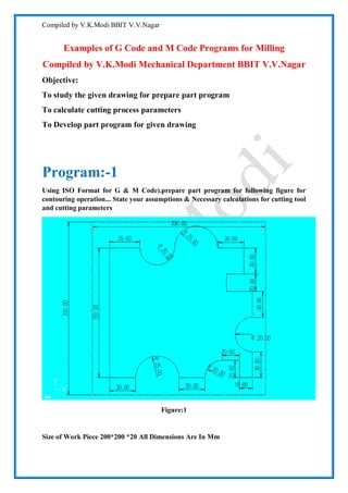
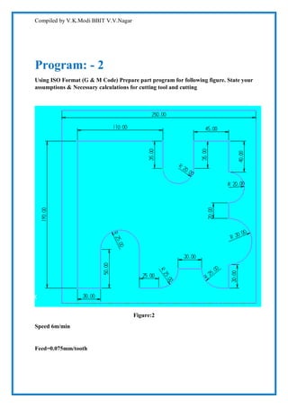
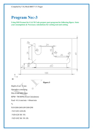
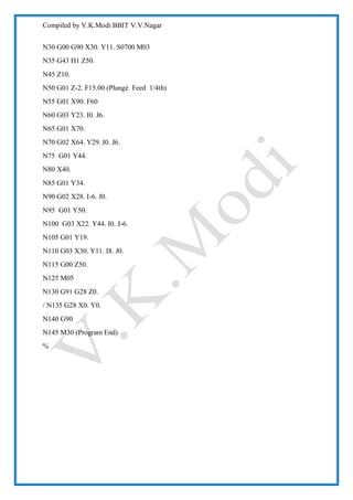

The document provides three G-code and M-code programs for milling different contour shapes. It includes assumptions and calculations for cutting parameters like cutting speed, tool diameter, feed rate, and RPM. Program 1 contours a shape with dimensions 200x200x20mm using an end mill with a 2mm diameter cutting at 140mm/min. Program 2 contours another shape using a 4mm end mill cutting at 70mm/min. Program 3 contours a third shape using a 5mm end mill cutting at 60mm/min. Calculations are provided for determining feed rate and RPM based on cutting speed, tool diameter and number of flutes.