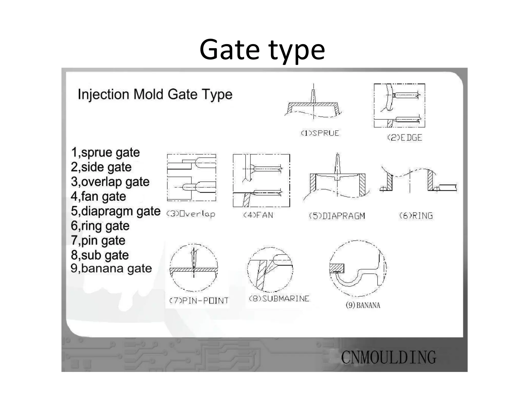
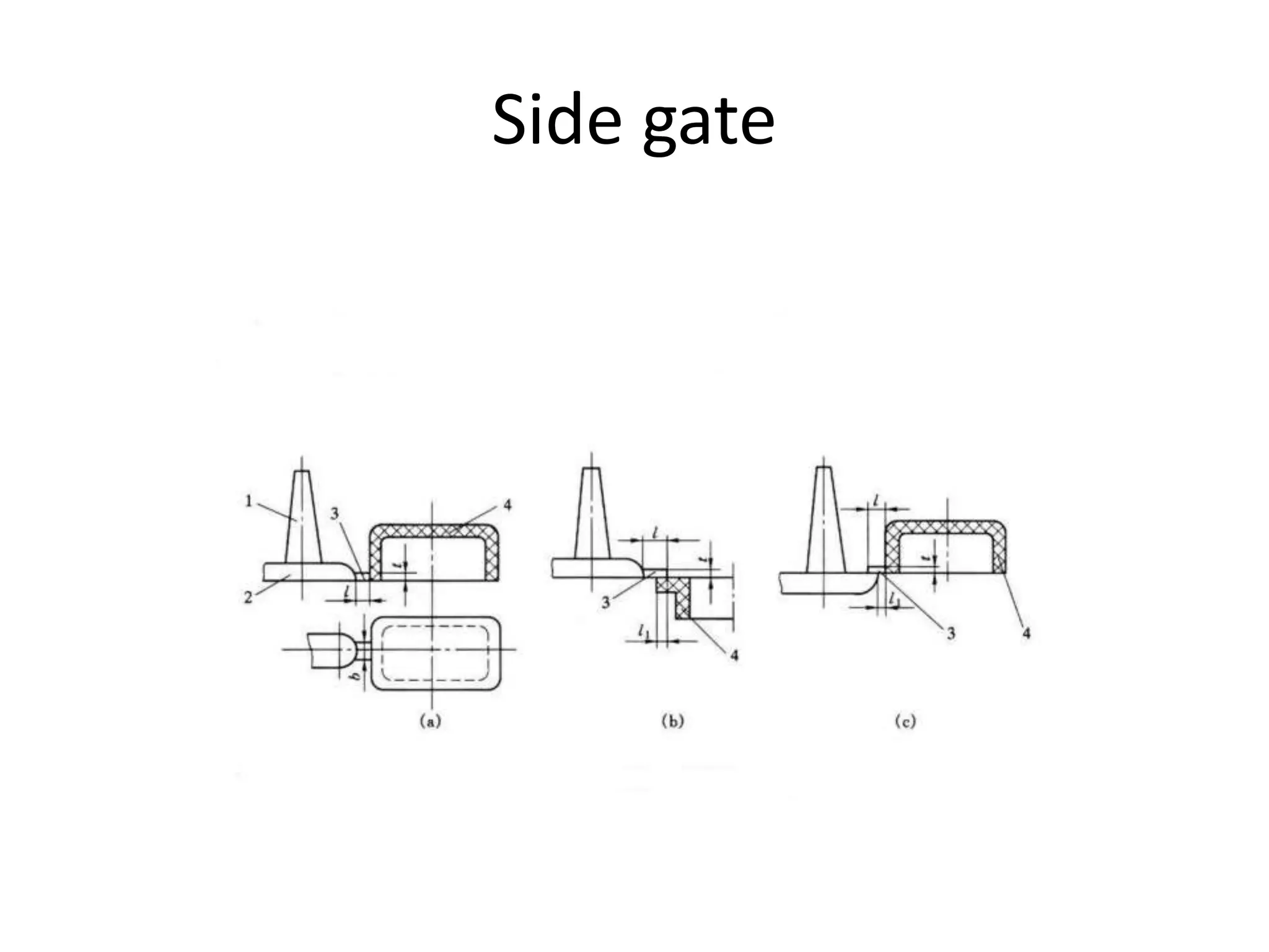
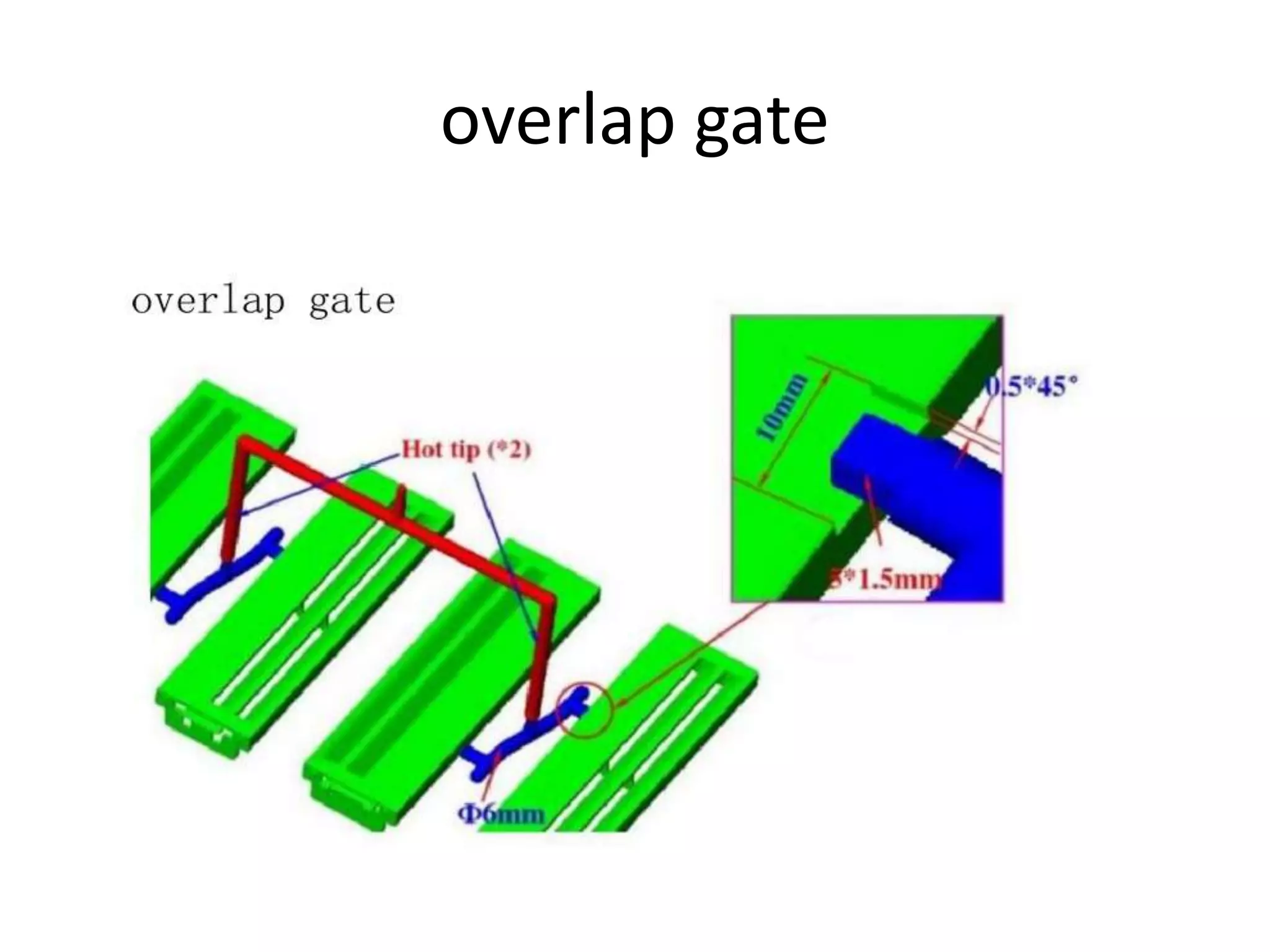
Injection mold gate type
Gate definition:
The final gate where the plastic melt enters the
cavity from the runner is the gate, which
connects the end of the gating system with
the cavity.
Injection mold gate
• Gates can be divided into large gates and
small gates according to their cross-sectional
dimensions.
Large gate:
The cross-sectional size is greater than or equal
to the runner area, and has no obvious effect
on the filling flow and pressure holding
process. It is called an unrestricted gate. Its
melt filling flow resistance is small, which is
conducive to material and pressure
transmission, but the gate is slow to set and
seal, it is easy to flow back at the gate, and the
residue is difficult to remove.
Small gate
• Small gate:
• The cross-sectional area is about 3%-9% of the
runner, which has a significant impact on the
filling speed, refill time, material flow state,
pressure drop, etc. It is called a restrictive gate.
• If the gate is too small, it is easy to cause
appearance defects such as insufficient filling,
shrinkage, fusion line, etc., and molding
shrinkage will increase.
• If the gate is too large, excess residual stress
will be generated around the gate, causing the
molded product to deform or crack.
Gate type
Application of sprue gate:
1).Because of the small pressure loss, it can be
used for large and deep barrel-shaped parts.
For shallow and flat rubber parts, due to
shrinkage and stress. Prone to warpage and
deformation.
2). For plastic parts whose appearance does not
allow gate marks, the gate can be set on the
inner surface of the plastic part.
Side gate application:
suitable for various shapes of plastic parts, but
not suitable for thin and long barrel-shaped
plastic parts.
Side gate
Overlap gate application:
suitable for flat-shaped plastic parts that require
surface quality.
overlap gate
Fan gate is suitable for:
It is commonly used to form thin-film plastic
parts with large width and transparent plastic
parts with poor flow properties, such as: PC,
PMMA, etc.
Fan gate
Pin gate application:
It is often applied to larger surfaces and bottom
shells. A reasonable distribution of gates can
help reduce the length of the flow path and
obtain a more ideal weld line distribution;
It can also be used for long barrel-shaped plastic
parts to improve exhaust.
Pin gate
Banana gate application:
commonly used in ABS, HIPS. It is not suitable
for crystalline materials such as POM and PBT,
nor is it suitable for materials with good
rigidity such as PC and PMMA, to prevent the
curved runner from being broken and blocking
the gate.
Banana gate
Sub gate application:
It is suitable for plastic parts whose appearance
does not allow the traces of the gate to be
exposed. It should be ensured that the resistance
of each cavity from the gate to the cavity is as
close as possible to avoid stagnation in order to
obtain a better flow balance.
Note: It can be submerged in front and back mold
bone position, side wall, submerged thimble and
other positions.
Sub gate

Injection mold gate type

  • 1.
    Injection mold gatetype Gate definition: The final gate where the plastic melt enters the cavity from the runner is the gate, which connects the end of the gating system with the cavity.
  • 2.
  • 3.
    • Gates canbe divided into large gates and small gates according to their cross-sectional dimensions.
  • 4.
    Large gate: The cross-sectionalsize is greater than or equal to the runner area, and has no obvious effect on the filling flow and pressure holding process. It is called an unrestricted gate. Its melt filling flow resistance is small, which is conducive to material and pressure transmission, but the gate is slow to set and seal, it is easy to flow back at the gate, and the residue is difficult to remove.
  • 5.
    Small gate • Smallgate: • The cross-sectional area is about 3%-9% of the runner, which has a significant impact on the filling speed, refill time, material flow state, pressure drop, etc. It is called a restrictive gate.
  • 6.
    • If thegate is too small, it is easy to cause appearance defects such as insufficient filling, shrinkage, fusion line, etc., and molding shrinkage will increase. • If the gate is too large, excess residual stress will be generated around the gate, causing the molded product to deform or crack.
  • 7.
  • 8.
    Application of spruegate: 1).Because of the small pressure loss, it can be used for large and deep barrel-shaped parts. For shallow and flat rubber parts, due to shrinkage and stress. Prone to warpage and deformation. 2). For plastic parts whose appearance does not allow gate marks, the gate can be set on the inner surface of the plastic part.
  • 9.
    Side gate application: suitablefor various shapes of plastic parts, but not suitable for thin and long barrel-shaped plastic parts.
  • 10.
  • 11.
    Overlap gate application: suitablefor flat-shaped plastic parts that require surface quality.
  • 12.
  • 13.
    Fan gate issuitable for: It is commonly used to form thin-film plastic parts with large width and transparent plastic parts with poor flow properties, such as: PC, PMMA, etc.
  • 14.
  • 15.
    Pin gate application: Itis often applied to larger surfaces and bottom shells. A reasonable distribution of gates can help reduce the length of the flow path and obtain a more ideal weld line distribution; It can also be used for long barrel-shaped plastic parts to improve exhaust.
  • 16.
  • 17.
    Banana gate application: commonlyused in ABS, HIPS. It is not suitable for crystalline materials such as POM and PBT, nor is it suitable for materials with good rigidity such as PC and PMMA, to prevent the curved runner from being broken and blocking the gate.
  • 18.
  • 19.
    Sub gate application: Itis suitable for plastic parts whose appearance does not allow the traces of the gate to be exposed. It should be ensured that the resistance of each cavity from the gate to the cavity is as close as possible to avoid stagnation in order to obtain a better flow balance. Note: It can be submerged in front and back mold bone position, side wall, submerged thimble and other positions.
  • 20.