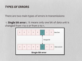
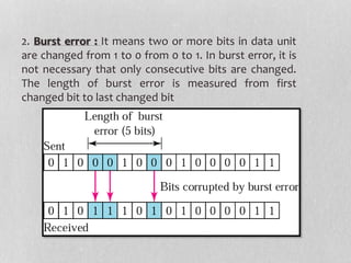
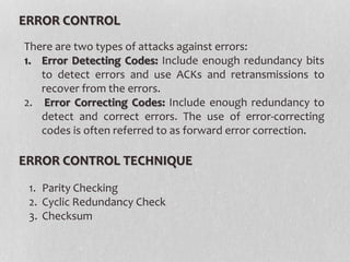
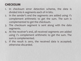
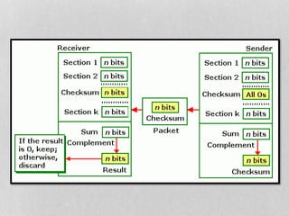
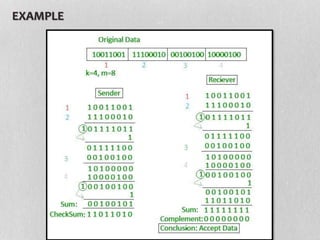
Presented by :
Ahtesham Ullah Khan
1604610013
CSE 3RD YR
ERROR CONTROL IN
NETWORK LAYER
There are two main types of errors in transmissions:
1. Single bit error : It means only one bit of data unit is
changed from 1 to 0 or from 0 to 1.
TYPES OF ERRORS
2. Burst error : It means two or more bits in data unit
are changed from 1 to 0 from 0 to 1. In burst error, it is
not necessary that only consecutive bits are changed.
The length of burst error is measured from first
changed bit to last changed bit
ERROR CONTROL
1. Parity Checking
2. Cyclic Redundancy Check
3. Checksum
There are two types of attacks against errors:
1. Error Detecting Codes: Include enough redundancy bits
to detect errors and use ACKs and retransmissions to
recover from the errors.
2. Error Correcting Codes: Include enough redundancy to
detect and correct errors. The use of error-correcting
codes is often referred to as forward error correction.
ERROR CONTROL TECHNIQUE
PARITY CHECK TECHNIQUE
A parity check is the process that ensures accurate data
transmission between nodes during communication. A parity
bit is appended to the original data bits to create an even or
odd bit number; the number of bits with value one. The
source then transmits this data via a link, and bits are checked
and verified at the destination. Data is considered accurate if
the number of bits (even or odd) matches the number
transmitted from the source.
TYPE OF PARITY
1. Even Parity
2. Odd Parity
CYCLIC REDUNDANCY CHECK
1. In CRC, a sequence of redundant bits, called cyclic
redundancy check bits, are appended to the end
of data unit so that the resulting data unit
becomes exactly divisible by a second,
predetermined binary number.
2. At the destination, the incoming data unit is
divided by the same number. If at this step there
is no remainder, the data unit is assumed to be
correct and is therefore accepted.
3. A remainder indicates that the data unit has been
damaged in transit and therefore must be
rejected.
EXAMPLE :
Data word : 1010 Divisor : 1011
1011 1010000
1
1011
1000
1011
011 CRC
1011 1010
1
1011
1011
1011
0000 ACCEPTED
00 1
001
CHECKSUM
1. In checksum error detection scheme, the data is
divided into k segments each of m bits.
2. In the sender’s end the segments are added using 1’s
complement arithmetic to get the sum. The sum is
complemented to get the checksum.
3. The checksum segment is sent along with the data
segments.
4. At the receiver’s end, all received segments are added
using 1’s complement arithmetic to get the sum. The
sum is complemented.
5. If the result is zero, the received data is accepted;
otherwise discarded.
EXAMPLE
Error Control In Network Layer

Error Control In Network Layer

  • 1.
    Presented by : AhteshamUllah Khan 1604610013 CSE 3RD YR ERROR CONTROL IN NETWORK LAYER
  • 2.
    There are twomain types of errors in transmissions: 1. Single bit error : It means only one bit of data unit is changed from 1 to 0 or from 0 to 1. TYPES OF ERRORS
  • 3.
    2. Burst error: It means two or more bits in data unit are changed from 1 to 0 from 0 to 1. In burst error, it is not necessary that only consecutive bits are changed. The length of burst error is measured from first changed bit to last changed bit
  • 4.
    ERROR CONTROL 1. ParityChecking 2. Cyclic Redundancy Check 3. Checksum There are two types of attacks against errors: 1. Error Detecting Codes: Include enough redundancy bits to detect errors and use ACKs and retransmissions to recover from the errors. 2. Error Correcting Codes: Include enough redundancy to detect and correct errors. The use of error-correcting codes is often referred to as forward error correction. ERROR CONTROL TECHNIQUE
  • 5.
    PARITY CHECK TECHNIQUE Aparity check is the process that ensures accurate data transmission between nodes during communication. A parity bit is appended to the original data bits to create an even or odd bit number; the number of bits with value one. The source then transmits this data via a link, and bits are checked and verified at the destination. Data is considered accurate if the number of bits (even or odd) matches the number transmitted from the source. TYPE OF PARITY 1. Even Parity 2. Odd Parity
  • 7.
    CYCLIC REDUNDANCY CHECK 1.In CRC, a sequence of redundant bits, called cyclic redundancy check bits, are appended to the end of data unit so that the resulting data unit becomes exactly divisible by a second, predetermined binary number. 2. At the destination, the incoming data unit is divided by the same number. If at this step there is no remainder, the data unit is assumed to be correct and is therefore accepted. 3. A remainder indicates that the data unit has been damaged in transit and therefore must be rejected.
  • 9.
    EXAMPLE : Data word: 1010 Divisor : 1011 1011 1010000 1 1011 1000 1011 011 CRC 1011 1010 1 1011 1011 1011 0000 ACCEPTED 00 1 001
  • 10.
    CHECKSUM 1. In checksumerror detection scheme, the data is divided into k segments each of m bits. 2. In the sender’s end the segments are added using 1’s complement arithmetic to get the sum. The sum is complemented to get the checksum. 3. The checksum segment is sent along with the data segments. 4. At the receiver’s end, all received segments are added using 1’s complement arithmetic to get the sum. The sum is complemented. 5. If the result is zero, the received data is accepted; otherwise discarded.
  • 12.