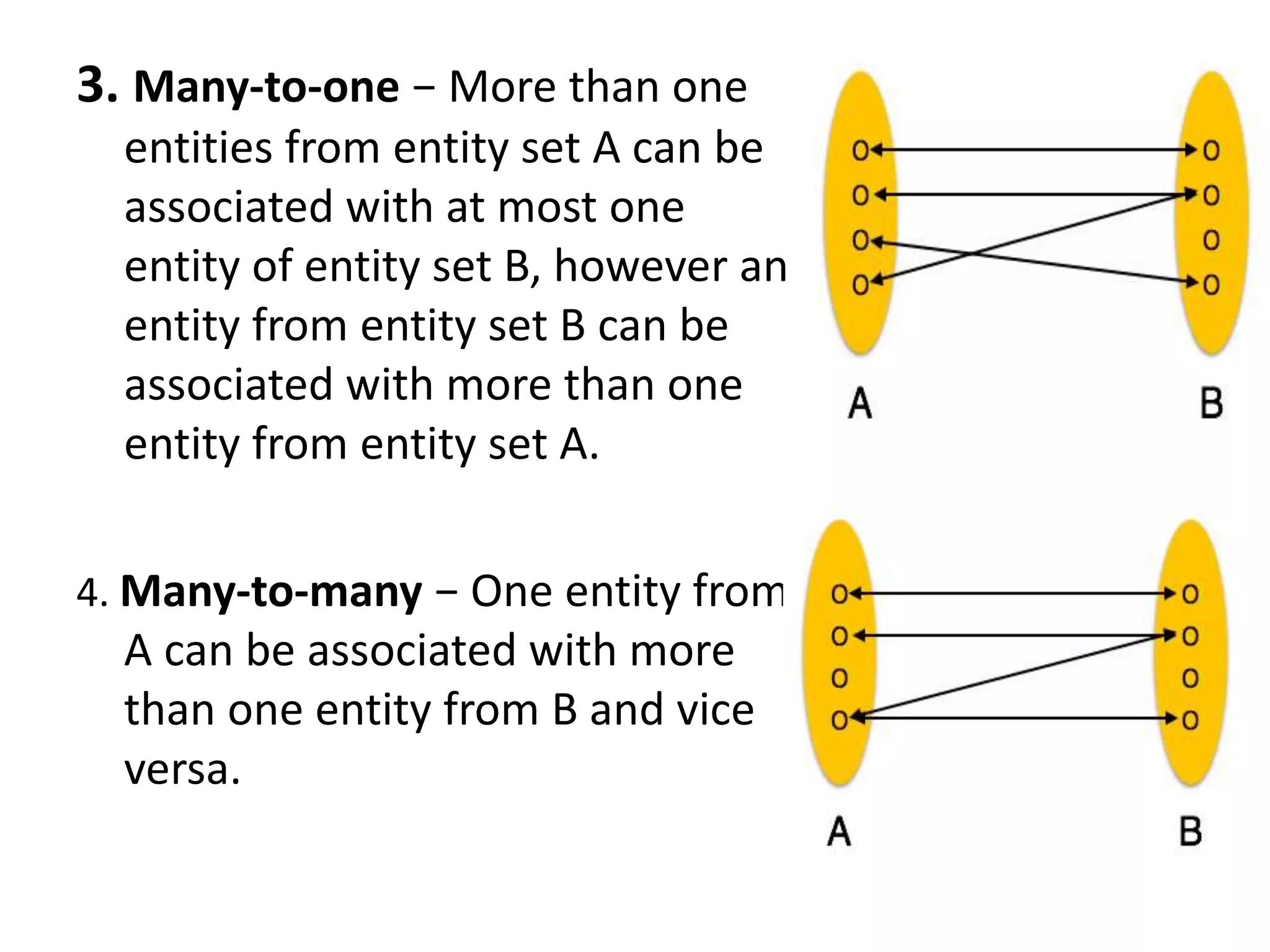
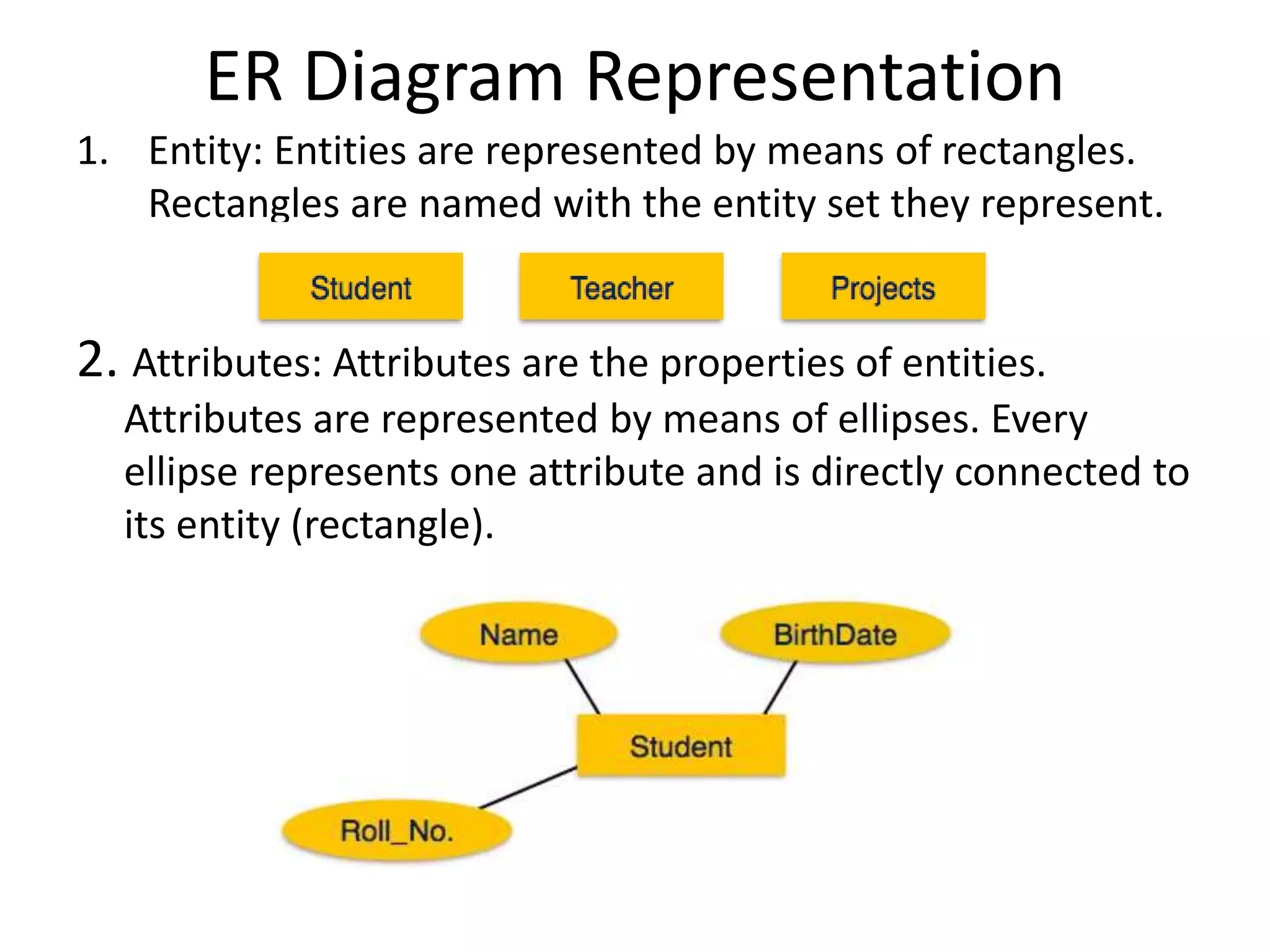
ER diagrams
The ER model defines the conceptual view of a
database. It works around real-world entities
and the associations among them.
• Entity: An entity can be a real-world object,
either animate or inanimate, that can be
easily identifiable.
• Attributes: Entities are represented by means
of their properties, called attributes. All
attributes have values.
Types of Attributes
• Simple attribute
• Composite attribute
• Derived attribute
• Single-value attribute
• Multi-value attribute
Relationship
The association among entities is called a
relationship.
Degree of Relationship
• The number of participating entities in a
relationship defines the degree of the
relationship.
Binary = degree 2
Ternary = degree 3
n-ary = degree
Mapping Cardinalities
1. One-to-one − One entity from
entity set A can be associated
with at most one entity of
entity set B and vice versa.
2. One-to-many − One entity
from entity set A can be
associated with more than one
entities of entity set B however
an entity from entity set B, can
be associated with at most one
entity.
3. Many-to-one − More than one
entities from entity set A can be
associated with at most one
entity of entity set B, however an
entity from entity set B can be
associated with more than one
entity from entity set A.
4. Many-to-many − One entity from
A can be associated with more
than one entity from B and vice
versa.
ER Diagram Representation
1. Entity: Entities are represented by means of rectangles.
Rectangles are named with the entity set they represent.
2. Attributes: Attributes are the properties of entities.
Attributes are represented by means of ellipses. Every
ellipse represents one attribute and is directly connected to
its entity (rectangle).
Composite attribute
Multi-valued attribute
Derived attribute
Relationship
Relationships are represented by diamond-shaped box.
All the entities (rectangles) participating in a
relationship, are connected to it by a line.
Binary Relationship and Cardinality
A relationship where two entities are participating is
called a binary relationship. Cardinality is the
number of instance of an entity from a relation that
can be associated with the relation.
• One-to-one − When only one instance of an entity is
associated with the relationship, it is marked as '1:1'.
• One-to-many − When more than one instance of an
entity is associated with a relationship, it is marked
as '1:N‘.
• Many-to-one − When more than one instance of
entity is associated with the relationship, it is marked
as 'N:1'.
• Many-to-many - more than one instance of an entity on
the left and more than one instance of an entity on the
right can be associated with the relationship.

Er diagrams

  • 1.
    ER diagrams The ERmodel defines the conceptual view of a database. It works around real-world entities and the associations among them. • Entity: An entity can be a real-world object, either animate or inanimate, that can be easily identifiable. • Attributes: Entities are represented by means of their properties, called attributes. All attributes have values.
  • 2.
    Types of Attributes •Simple attribute • Composite attribute • Derived attribute • Single-value attribute • Multi-value attribute
  • 3.
    Relationship The association amongentities is called a relationship. Degree of Relationship • The number of participating entities in a relationship defines the degree of the relationship. Binary = degree 2 Ternary = degree 3 n-ary = degree
  • 4.
    Mapping Cardinalities 1. One-to-one− One entity from entity set A can be associated with at most one entity of entity set B and vice versa. 2. One-to-many − One entity from entity set A can be associated with more than one entities of entity set B however an entity from entity set B, can be associated with at most one entity.
  • 5.
    3. Many-to-one −More than one entities from entity set A can be associated with at most one entity of entity set B, however an entity from entity set B can be associated with more than one entity from entity set A. 4. Many-to-many − One entity from A can be associated with more than one entity from B and vice versa.
  • 6.
    ER Diagram Representation 1.Entity: Entities are represented by means of rectangles. Rectangles are named with the entity set they represent. 2. Attributes: Attributes are the properties of entities. Attributes are represented by means of ellipses. Every ellipse represents one attribute and is directly connected to its entity (rectangle).
  • 7.
  • 8.
    Relationship Relationships are representedby diamond-shaped box. All the entities (rectangles) participating in a relationship, are connected to it by a line. Binary Relationship and Cardinality A relationship where two entities are participating is called a binary relationship. Cardinality is the number of instance of an entity from a relation that can be associated with the relation. • One-to-one − When only one instance of an entity is associated with the relationship, it is marked as '1:1'.
  • 9.
    • One-to-many −When more than one instance of an entity is associated with a relationship, it is marked as '1:N‘. • Many-to-one − When more than one instance of entity is associated with the relationship, it is marked as 'N:1'. • Many-to-many - more than one instance of an entity on the left and more than one instance of an entity on the right can be associated with the relationship.