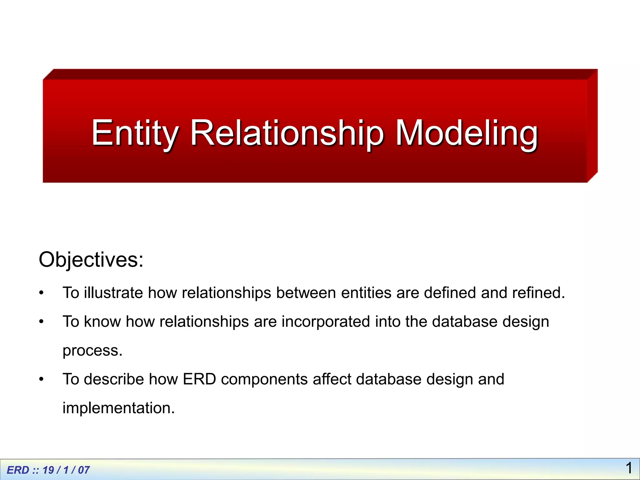
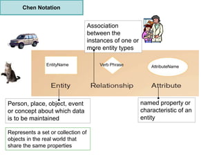
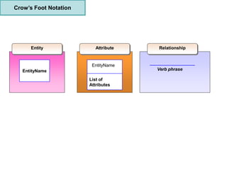
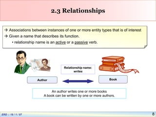
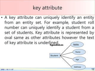
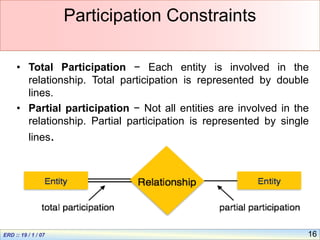
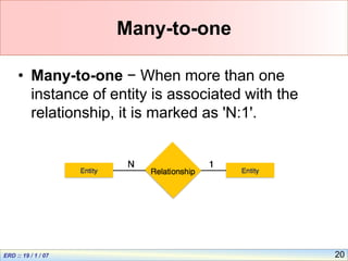
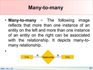
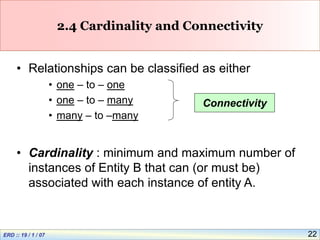
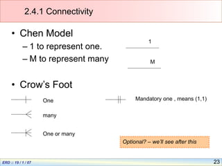
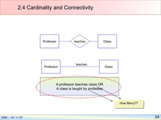
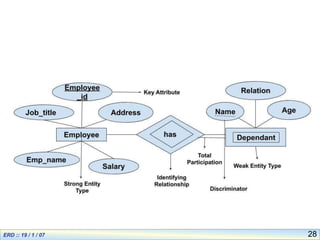
Entity Relationship modeling is used to define relationships between entities in a database. It involves creating Entity Relationship Diagrams which use entities, attributes, and relationships to represent how data is connected. The ER diagram defines the entities, their attributes, and the relationships between entities. This modeling helps with database design and implementation by illustrating how data is structured and related.
Considering Company as a Mini world Problem we need to design the Database.
Company Database consists of:
Company Info
Employee Info
Project Info
The Formulated Requirements are:
The company is organized into departments. Each department has a unique name, a unique number, and a particular employee who manages the department. We keep track of the start date when that employee began managing the department. A department may have several location
A department controls a number of projects, each of which has a unique name, a unique number, and a single location
We store each employee’s name, Social Security number, address, salary, sex (gender), and birth date. An employee is assigned to one department, but may work on several projects, which are not necessarily controlled by the same department. We keep track of the current number of hours per week that an employee works on each project. We also keep track of the direct supervisor of each employee (who is another employee).
We want to keep track of the dependents of each employee for insurance purposes
This Presentation would make you understand the Fundamentals of Database Design, Data Models (Conceptual, Logical & Physical), ERD, ERM. Also, have real-life examples and case study to understand better.
The following presentation represents database keys and its types, and also database relationship and its types with references. It will help you to know about what is keys and database relationship.
Entity type
Entity sets
Attributes and keys
Relationship model
Mapping Constraints
The ER Model
Cardinality Constraints
Generalization, Specialization and Aggregation
ER Diagram & Database design with the ER Model
Introduction
Relational Model
Concepts
Characteristics
How to Make a Field invisible in Odoo 17Celine George
It is possible to hide or invisible some fields in odoo. Commonly using “invisible” attribute in the field definition to invisible the fields. This slide will show how to make a field invisible in odoo 17.
The French Revolution, which began in 1789, was a period of radical social and political upheaval in France. It marked the decline of absolute monarchies, the rise of secular and democratic republics, and the eventual rise of Napoleon Bonaparte. This revolutionary period is crucial in understanding the transition from feudalism to modernity in Europe.
For more information, visit-www.vavaclasses.com
Synthetic Fiber Construction in lab .pptxPavel ( NSTU)
Synthetic fiber production is a fascinating and complex field that blends chemistry, engineering, and environmental science. By understanding these aspects, students can gain a comprehensive view of synthetic fiber production, its impact on society and the environment, and the potential for future innovations. Synthetic fibers play a crucial role in modern society, impacting various aspects of daily life, industry, and the environment. ynthetic fibers are integral to modern life, offering a range of benefits from cost-effectiveness and versatility to innovative applications and performance characteristics. While they pose environmental challenges, ongoing research and development aim to create more sustainable and eco-friendly alternatives. Understanding the importance of synthetic fibers helps in appreciating their role in the economy, industry, and daily life, while also emphasizing the need for sustainable practices and innovation.
Biological screening of herbal drugs: Introduction and Need for
Phyto-Pharmacological Screening, New Strategies for evaluating
Natural Products, In vitro evaluation techniques for Antioxidants, Antimicrobial and Anticancer drugs. In vivo evaluation techniques
for Anti-inflammatory, Antiulcer, Anticancer, Wound healing, Antidiabetic, Hepatoprotective, Cardio protective, Diuretics and
Antifertility, Toxicity studies as per OECD guidelines
Embracing GenAI - A Strategic ImperativePeter Windle
Artificial Intelligence (AI) technologies such as Generative AI, Image Generators and Large Language Models have had a dramatic impact on teaching, learning and assessment over the past 18 months. The most immediate threat AI posed was to Academic Integrity with Higher Education Institutes (HEIs) focusing their efforts on combating the use of GenAI in assessment. Guidelines were developed for staff and students, policies put in place too. Innovative educators have forged paths in the use of Generative AI for teaching, learning and assessments leading to pockets of transformation springing up across HEIs, often with little or no top-down guidance, support or direction.
This Gasta posits a strategic approach to integrating AI into HEIs to prepare staff, students and the curriculum for an evolving world and workplace. We will highlight the advantages of working with these technologies beyond the realm of teaching, learning and assessment by considering prompt engineering skills, industry impact, curriculum changes, and the need for staff upskilling. In contrast, not engaging strategically with Generative AI poses risks, including falling behind peers, missed opportunities and failing to ensure our graduates remain employable. The rapid evolution of AI technologies necessitates a proactive and strategic approach if we are to remain relevant.
Francesca Gottschalk - How can education support child empowerment.pptxEduSkills OECD
Francesca Gottschalk from the OECD’s Centre for Educational Research and Innovation presents at the Ask an Expert Webinar: How can education support child empowerment?
Acetabularia Information For Class 9 .docxvaibhavrinwa19
Acetabularia acetabulum is a single-celled green alga that in its vegetative state is morphologically differentiated into a basal rhizoid and an axially elongated stalk, which bears whorls of branching hairs. The single diploid nucleus resides in the rhizoid.
Chapter 3 - Islamic Banking Products and Services.pptx
ERD(2).ppt
1. 1
Entity Relationship Modeling
Objectives:
• To illustrate how relationships between entities are defined and refined.
• To know how relationships are incorporated into the database design
process.
• To describe how ERD components affect database design and
implementation.
2. 2
Entity-Relationship (ER) Modeling.
• Entity Relationship (ER) Diagram
– A detailed, logical representation of the entities,
associations and data elements for an organization or
business
• Notation uses three main constructs
– Data entities
– Relationships
– Attributes Chen Model &
Crow’s Foot
Model
3. Person, place, object, event
or concept about which data
is to be maintained
named property or
characteristic of an
entity
Association
between the
instances of one or
more entity types
Represents a set or collection of
objects in the real world that
share the same properties
Chen Notation
EntityName Verb Phrase AttributeName
5. 5
2.1 Entities
• Examples of entities:
– Person: EMPLOYEE, STUDENT, PATIENT
– Place: STORE, WAREHOUSE
– Object: MACHINE, PRODUCT, CAR
– Event: SALE,REGISTRATION, RENEWAL
– Concept: ACCOUNT, COURSE
• Guidelines for naming and defining entity types:
– An entity type should be descriptive and specific
– An entity name should be concise
– Event entity types should be named for the result of the event, not
the activity or process of the event.
6. 6
2.2 Attributes
• Example of entity types and associated attributes:
STUDENT: Student_ID, Student_Name, Home_Address,
Phone_Number, Major
• Guidelines for naming attributes:
– An attribute name is a noun.
– An attribute name should be unique
– To make an attribute name unique and clear, each attribute name
should follow a standard format
– Similar attributes of different entity types should use similar but
distinguishing names.
8. 8
2.3 Relationships
Associations between instances of one or more entity types that is of interest
Given a name that describes its function.
• relationship name is an active or a passive verb.
Author Book
Relationship name:
writes
An author writes one or more books
A book can be written by one or more authors.
9. 9
2.3.1 Degree of Relationships
• Degree: number of entity types that participate in a relationship
• Three cases
– Unary: between two instances of one entity type
– Binary: between the instances of two entity types
– Ternary: among the instances of three entity types
10. 10
main components and its symbols in
ER Diagrams:
Following are the main components and its symbols in ER Diagrams:
•Rectangles: This Entity Relationship Diagram symbol represents entity types
•Ellipses : Symbol represent attributes
•Diamonds: This symbol represents relationship types
•Lines: It links attributes to entity types and entity types with other relationship types
•Primary key: attributes are underlined
•Double Ellipses: Represent multi-valued attributes
11. 11
Attribute
• An attribute describes the property of an
entity. An attribute is represented as Oval in
an ER diagram. There are four types of
attributes:
• 1. Key attribute
2. Composite attribute
3. Multivalued attribute
4. Derived attribute
12. 12
key attribute
• A key attribute can uniquely identify an entity
from an entity set. For example, student roll
number can uniquely identify a student from a
set of students. Key attribute is represented by
oval same as other attributes however the text
of key attribute is underlined.
13. 13
composite attribute
An attribute that is a combination of other attributes is known as composite
attribute. For example, In student entity, the student address is a composite
attribute as an address is composed of other attributes such as pin code, state,
country.
14. 14
Multivalued attribute:
• An attribute that can hold multiple values is
known as multivalued attribute. It is
represented with double ovals in an ER
Diagram. For example – A person can have
more than one phone numbers so the
phone number attribute is multivalued.
15. 15
4. Derived attribute:
• A derived attribute is one whose value is
dynamic and derived from another attribute.
It is represented by dashed oval in an ER
Diagram. For example – Person age is a
derived attribute as it changes over time
and can be derived from another attribute
(Date of birth).
16. 16
Participation Constraints
• Total Participation − Each entity is involved in the
relationship. Total participation is represented by double
lines.
• Partial participation − Not all entities are involved in the
relationship. Partial participation is represented by single
lines.
17. 17
• A relationship where two entities are
participating is called a binary relationship.
Cardinality is the number of instance of an
entity from a relation that can be associated
with the relation.
18. 18
One-to-one −
• When only one instance of an entity is
associated with the relationship, it is marked
as '1:1'.
19. 19
One-to-many
• One-to-many − When more than one
instance of an entity is associated with a
relationship, it is marked as '1:N'.
20. 20
Many-to-one
• Many-to-one − When more than one
instance of entity is associated with the
relationship, it is marked as 'N:1'.
21. 21
Many-to-many
• Many-to-many − The following image
reflects that more than one instance of an
entity on the left and more than one instance
of an entity on the right can be associated
with the relationship. It depicts many-to-
many relationship.
•
22. 22
2.4 Cardinality and Connectivity
• Relationships can be classified as either
• one – to – one
• one – to – many
• many – to –many
• Cardinality : minimum and maximum number of
instances of Entity B that can (or must be)
associated with each instance of entity A.
Connectivity
23. 23
2.4.1 Connectivity
• Chen Model
– 1 to represent one.
– M to represent many
• Crow’s Foot
many
One
One or many
1
M
Mandatory one , means (1,1)
Optional? – we’ll see after this
24. 24
2.4 Cardinality and Connectivity
Professor Class
teaches
A professor teaches class OR
A class is taught by professor
How Many??
Professor Class
teaches
25. 25
Strong Entity
• Strong Entity is independent to any other
entity in the schema.
• A strong entity always have a primary key. In
ER diagram, a strong entity is represented
by rectangle.
• Relationship between two strong entities is
represented by a diamond.
• A set of strong entities is known as strong
entity set.
27. 27
Weak Entity
• Weak entity is dependent on strong entity
and cannot exists without a corresponding
strong.
• It has a foreign key which relates it to a
strong entity. A weak entity is represented by
double rectangle.
• Relationship between a strong entity and a
weak entity is represented by double
diamond. The foreign key is also called a
partial discriminator key.
29. 29
Strong Entity Set Weak Entity Set
Strong entity set always has a primary key.
It does not have enough attributes to build a
primary key.
It is represented by a rectangle symbol. It is represented by a double rectangle symbol.
It contains a Primary key represented by the
underline symbol.
It contains a Partial Key which is represented by a
dashed underline symbol.
The member of a strong entity set is called as
dominant entity set.
The member of a weak entity set called as a
subordinate entity set.
Primary Key is one of its attributes which helps to
identify its member.
In a weak entity set, it is a combination of primary
key and partial key of the strong entity set.
In the ER diagram the relationship between two
strong entity set shown by using a diamond
symbol.
The relationship between one strong and a weak
entity set shown by using the double diamond
symbol.
The connecting line of the strong entity set with the
relationship is single.
The line connecting the weak entity set for
identifying relationship is double.
Comparing Strong Entity and weak Entity
30. 30
What are Keys in DBMS?
• KEYS in DBMS is an attribute or set of
attributes which helps you to identify a
row(tuple) in a relation(table).
• They allow you to find the relation between
two tables.
• Key is also helpful for finding unique record
or row from the table. Database key is also
helpful for finding unique record or row from
the table.
34. 34
Primary Key
Primary Key: There can be more than one candidate key in relation out of which
one can be chosen as the primary key. For Example, STUD_NO, as well as
STUD_PHONE both, are candidate keys for relation STUDENT but STUD_NO can
be chosen as the primary key (only one out of many candidate keys).
35. 35
Candidate Key:
• The minimal set of attributes that can
uniquely identify a tuple is known as
a candidate key.
• For Example, STUD_NO in STUDENT
relation.
• The candidate key can be simple (having
only one attribute) or composite as well. For
Example, {STUD_NO, COURSE_NO} is a
composite candidate key for relation
36. 36
• Super Key: The set of attributes that can
uniquely identify a tuple is known as Super
Key. For Example, STUD_NO, (STUD_NO,
STUD_NAME), etc.
• Adding zero or more attributes to the
candidate key generates the super key.
• A candidate key is a super key but vice
versa is not true.
37. 37
Alternate Key:
• The candidate key other than the primary
key is called an alternate key.
• For Example, STUD_NO, as well as
STUD_PHONE both, are candidate keys for
relation STUDENT but STUD_PHONE will
be an alternate key (only one out of many
candidate keys).
38. 38
Foreign keys
• Foreign keys are the column of the table
which is used to point to the primary key of
another table.
39. 39
Composite Key
• A composite key is a key that contains two
or more attributes that help to identify a
record in the table uniquely.
• we have to use this combination to identify
the records separately. It is not possible to
use individual attributes to identify the
records.
40. 40
• For example, assume that there is a table to store
the marks of the students.
• It has 4 attributes or columns: student_id,
subject_id, marks and exam_name.
• In this table, we cannot consider either the
student_id or the subject_id as the primary key
because we cannot uniquely identify the records
by using them. However, we can identify each
record by using the combination of student_id and
subject_id. Therefore, this combination is
the primary key. Furthermore, this combination is
also a composite key.
42. 42
Surrogate key
Surrogate key also called a synthetic primary
key, is generated when a new record is
inserted into a table automatically by a
database that can be declared as the primary
key of that table . It is the sequential number
outside of the database that is made available
to the user and the application or it acts as an
object that is present in the database but is
not visible to the user or application.
43. 43
Example
Suppose we have two tables of two different
schools having the same column registration_no
, name and percentage , each table having its
own natural primary key, that is registration_no.
Table A Table B
registration_n
o
name percentage
CS107 Taylor 49
CS108 Simon 86
CS109 Sam 96
CS110 Andy 58
registration_n
o
name percentage
210101 Harry 90
210102 Maxwell 65
210103 Lee 87
210104 Chris 76
44. 44
Now, suppose we want to merge the details of both the schools in a single table
.
Resulting table will be –
46. 46
Sectorsssss Use of DBMS
Banking For customer information, account activities,
payments, deposits, loans, etc.
Airlines For reservations and schedule information.
Universities For student information, course registrations,
colleges and grades.
Telecommunication It helps to keep call records, monthly bills,
maintaining balances, etc.
Finance For storing information about stock, sales, and
purchases of financial instruments like stocks
and bonds.
Sales Use for storing customer, product & sales
information.
Manufacturing It is used for the management of supply chain
and for tracking production of items. Inventories
status in warehouses.
HR Management For information about employees, salaries,
payroll, deduction, generation of paychecks,
etc.