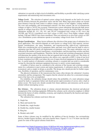
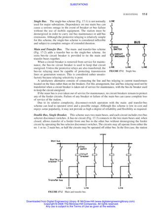
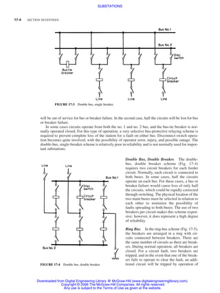
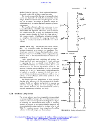
SlideShare a Scribd company logo
1 of 52
Download to read offline
SECTION 17
SUBSTATIONS
W. Bruce Dietzman
Project Engineering Manager, TXU Electric Delivery Company; Senior Member, IEEE;
Past Chair, IEEE/PES Substations Committee; Past VP-Technical Activities, IEEE/PES
Philip C. Bolin
General Manager, Substation Division Mitsubishi Electric Power Products, Inc.;
Fellow, IEEE; Past Chair, IEEE/PES Gas-Insulated Substations
Subcommittee; Member, CIGRE Working Group 23.10 GIS
CONTENTS
17.1 AIR-INSULATED SUBSTATIONS . . . . . . . . . . . . . . . . . . 17-1
17.1.1 Function of Substations . . . . . . . . . . . . . . . . . . . . 17-1
17.1.2 Design Objectives . . . . . . . . . . . . . . . . . . . . . . . . 17-1
17.1.3 Reliability Comparisons . . . . . . . . . . . . . . . . . . . 17-5
17.1.4 Arrangements and Equipment . . . . . . . . . . . . . . . 17-7
17.1.5 Site Selection . . . . . . . . . . . . . . . . . . . . . . . . . . . . 17-8
17.1.6 Substation Buses . . . . . . . . . . . . . . . . . . . . . . . . . 17-9
17.1.7 Clearance Requirements . . . . . . . . . . . . . . . . . . . 17-16
17.1.8 Mechanical and Electrical Forces . . . . . . . . . . . . . 17-18
17.1.9 Overvoltage and Overcurrent Protection . . . . . . . . 17-21
17.1.10 Substation Grounding . . . . . . . . . . . . . . . . . . . . . 17-32
17.1.11 Transformers . . . . . . . . . . . . . . . . . . . . . . . . . . . . 17-38
17.1.12 Surge Protection . . . . . . . . . . . . . . . . . . . . . . . . . 17-40
REFERENCES ON AIR-INSULATED SUBSTATIONS . . . . . . . . 17-43
17.2 GAS-INSULATED SUBSTATIONS . . . . . . . . . . . . . . . . . . 17-45
17.2.1 Introduction . . . . . . . . . . . . . . . . . . . . . . . . . . . . . 17-45
17.2.2 General Characteristics . . . . . . . . . . . . . . . . . . . . 17-45
17.2.3 Equipment . . . . . . . . . . . . . . . . . . . . . . . . . . . . . . 17-48
REFERENCES ON SF6
GAS-INSULATED SUBSTATIONS . . . . . 17-51
17.1 AIR-INSULATED SUBSTATIONS
17.1.1 Function of Substations
Transmission and Distribution Systems. In large, modern ac power systems, the transmission and
distribution systems function to deliver bulk power from generating sources to users at the load
centers. Transmission systems generally include generation switchyards, interconnecting transmis-
sion lines, autotransformers, switching stations, and step-down transformers. Distribution systems
include primary distribution lines or networks, transformer banks, and secondary lines or networks,
all of which serve the load area.
17.1.2 Design Objectives
As an integral part of the transmission or distribution systems, the substation or switching station
functions as a connection and switching point for generation sources, transmission or subtransmis-
sion lines, distribution feeders, and step-up and step-down transformers. The design objective for the
17-1
Beaty_Sec17.qxd 17/7/06 8:51 PM Page 17-1
Downloaded from Digital Engineering Library @ McGraw-Hill (www.digitalengineeringlibrary.com)
Copyright © 2006 The McGraw-Hill Companies. All rights reserved.
Any use is subject to the Terms of Use as given at the website.
Source: STANDARD HANDBOOK FOR ELECTRICAL ENGINEERS
17-2 SECTION SEVENTEEN
substation is to provide as high a level of reliability and flexibility as possible while satisfying system
requirements and minimizing total investment costs.
Voltage Levels. The selection of optimal system voltage levels depends on the load to be served
and the distance between the generation source and the load. Many large power plants are located
great distances from the load centers to address energy sources or fuel supplies, cooling methods,
site costs and availability, and environmental concerns. For these reasons, the use of transmission
voltages as high as 765 kV has occurred. Transmission system substations that provide bulk power
operate at voltages from 69 to 765 kV. Common voltage classes used in the United States for major
substations include 69, 115, 138, 161, and 230 kV (considered high voltage or HV class) and
345,500, and 765 kV (considered extra high voltage or EHV class). Even higher voltages which
include 1100 and 1500 kV have been considered. These are referred to as ultra high voltage or UHV
class. Distribution system substations operate at secondary voltage levels from 4 to 69 kV.
Design Considerations. Many factors influence the selection of the proper type of substation for a
given application. This selection depends on such factors as voltage level, load capacity, environ-
mental considerations, site space limitations, and transmission-line right-of-way requirements.
While also considering the cost of equipment, labor, and land, every effort must be made to select a
substation type that will satisfy all requirements at minimum costs. The major substation costs are
reflected in the number of power transformers, circuit breakers, and disconnecting switches and their
associated structures and foundations. Therefore, the bus layout and switching arrangement selected
will determine the number of the devices that are required and in turn the overall cost. The choice of
insulation levels and coordination practices also affects cost, especially at EHV. A drop of one level
in basic insulation level (BIL) can reduce the cost of major electrical equipment by thousands of dol-
lars. A careful analysis of alternative switching schemes is essential and can result in considerable
savings by choosing the minimum equipment necessary to satisfy system requirements.
A number of factors must be considered in the selection of bus layouts and switching arrange-
ments for a substation to meet system and station requirements. A substation must be safe, reliable,
economical, and as simple in design as possible. The design also should provide for further expan-
sion, flexibility of operation, and low maintenance costs.
The physical orientation of the transmission-line routes often dictates the substation’s location,
orientation, and bus arrangement. This requires that the selected site allow for a convenient arrange-
ment of the lines to be accomplished.
For reliability, the substation design should reduce the probability of a total substation outage
caused by faults or equipment failure and should permit rapid restoration of service after a fault or
failure occurs. The layout also should consider how future additions and extensions can be accom-
plished without interrupting service.
Bus Schemes. The substation design or scheme selected determines the electrical and physical
arrangement of the switching equipment. Different bus schemes can be selected as emphasis is shifted
between the factors of safety, reliability, economy, and simplicity dictated by the function and impor-
tance of the substation.
The substation bus schemes used most often are
1. Single bus
2. Main and transfer bus
3. Double bus, single breaker
4. Double bus, double breaker
5. Ring bus
6. Breaker and a half
Some of these schemes may be modified by the addition of bus-tie breakers, bus sectionalizing
devices, breaker bypass facilities, and extra transfer buses. Figures 17-1 to 17-6 show one-line dia-
grams for some of the typical schemes listed above.
Beaty_Sec17.qxd 17/7/06 8:51 PM Page 17-2
Downloaded from Digital Engineering Library @ McGraw-Hill (www.digitalengineeringlibrary.com)
Copyright © 2006 The McGraw-Hill Companies. All rights reserved.
Any use is subject to the Terms of Use as given at the website.
SUBSTATIONS
Single Bus. The single-bus scheme (Fig. 17-1) is not normally
used for major substations. Dependence on one main bus can
cause a serious outage in the event of breaker or bus failure
without the use of mobile equipment. The station must be
deenergized in order to carry out bus maintenance or add bus
extensions. Although the protective relaying is relatively simple
for this scheme, the single-bus scheme is considered inflexible
and subject to complete outages of extended duration.
Main and Transfer Bus. The main- and transfer-bus scheme
(Fig. 17-2) adds a transfer bus to the single-bus scheme. An
extra bus-tie circuit breaker is provided to tie the main and
transfer buses together.
When a circuit breaker is removed from service for mainte-
nance, the bus-tie circuit breaker is used to keep that circuit
energized. Unless the protective relays are also transferred, the
bus-tie relaying must be capable of protecting transmission
lines or generation sources. This is considered rather unsatis-
factory because relaying selectivity is poor.
A satisfactory alternative consists of connecting the line and bus relaying to current transformers
located on the lines rather than on the breakers. For this arrangement, line and bus relaying need not be
transferred when a circuit breaker is taken out of service for maintenance, with the bus-tie breaker used
to keep the circuit energized.
If the main bus is ever taken out of service for maintenance, no circuit breakers remain to protect
any of the feeder circuits. Failure of any breaker or failure of the main bus can cause complete loss
of service of the station.
Due to its relative complexity, disconnect-switch operation with the main- and transfer-bus
scheme can lead to operator error and a possible outage. Although this scheme is low in cost and
enjoys some popularity, it may not provide as high a degree of reliability and flexibility as required.
Double Bus, Single Breaker. This scheme uses two main buses, and each circuit includes two bus
selector disconnect switches. A bus-tie circuit (Fig. 17-3) connects to the two main buses and, when
closed, allows transfer of a feeder from one bus to the other bus without deenergizing the feeder
circuit by operating the bus selector disconnect switches. The circuits may all operate from either the
no. 1 or no. 2 main bus, or half the circuits may be operated off either bus. In the first case, the station
SUBSTATIONS 17-3
FIGURE 17-1 Single bus.
FIGURE 17-2 Main and transfer bus.
Beaty_Sec17.qxd 17/7/06 8:51 PM Page 17-3
Downloaded from Digital Engineering Library @ McGraw-Hill (www.digitalengineeringlibrary.com)
Copyright © 2006 The McGraw-Hill Companies. All rights reserved.
Any use is subject to the Terms of Use as given at the website.
SUBSTATIONS
will be out of service for bus or breaker failure. In the second case, half the circuits will be lost for bus
or breaker failure.
In some cases circuits operate from both the no. 1 and no. 2 bus, and the bus-tie breaker is nor-
mally operated closed. For this type of operation, a very selective bus-protective relaying scheme is
required to prevent complete loss of the station for a fault on either bus. Disconnect-switch opera-
tion becomes quite involved, with the possibility of operator error, injury, and possible outage. The
double-bus, single-breaker scheme is relatively poor in reliability and is not normally used for impor-
tant substations.
Double Bus, Double Breaker. The double-
bus, double breaker scheme (Fig. 17-4)
requires two circuit breakers for each feeder
circuit. Normally, each circuit is connected to
both buses. In some cases, half the circuits
operate on each bus. For these cases, a bus or
breaker failure would cause loss of only half
the circuits, which could be rapidly corrected
through switching. The physical location of the
two main buses must be selected in relation to
each other to minimize the possibility of
faults spreading to both buses. The use of two
breakers per circuit makes this scheme expen-
sive; however, it does represent a high degree
of reliability.
Ring Bus. In the ring-bus scheme (Fig. 17-5),
the breakers are arranged in a ring with cir-
cuits connected between breakers. There are
the same number of circuits as there are break-
ers. During normal operation, all breakers are
closed. For a circuit fault, two breakers are
tripped, and in the event that one of the break-
ers fails to operate to clear the fault, an addi-
tional circuit will be tripped by operation of
17-4 SECTION SEVENTEEN
FIGURE 17-4 Double bus, double breaker.
FIGURE 17-3 Double bus, single breaker.
Beaty_Sec17.qxd 17/7/06 8:51 PM Page 17-4
Downloaded from Digital Engineering Library @ McGraw-Hill (www.digitalengineeringlibrary.com)
Copyright © 2006 The McGraw-Hill Companies. All rights reserved.
Any use is subject to the Terms of Use as given at the website.
SUBSTATIONS
breaker-failure backup relays. During breaker maintenance,
the ring is broken, but all lines remain in service.
The circuits connected to the ring are arranged so that
sources are alternated with loads. For an extended circuit
outage, the line-disconnect switch may be opened, and the
ring can be closed. No changes to protective relays are
required for any of the various operating conditions or during
maintenance.
The ring-bus scheme is relatively economical in cost,
has good reliability, is flexible, and is normally consid-
ered suitable for important substations up to a limit of
five circuits. Protective relaying and automatic reclosing
are more complex than for previously described schemes.
It is common practice to build major substations initially
as a ring bus; for more than five outgoing circuits, the
ring bus is usually converted to the breaker-and-a-half
scheme.
Breaker and a Half. The breaker-and-a half scheme
(Fig. 17-6), sometimes called the three-switch scheme,
has three breakers in series between two main buses. Two
circuits are connected between the three breakers, hence
the term breaker and a half. This pattern is repeated along
the main buses so that one and a half breakers are used for
each circuit.
Under normal operating conditions, all breakers are
closed, and both buses are energized. A circuit is tripped
by opening the two associated circuit breakers. Tie-
breaker failure will trip one additional circuit, but no addi-
tional circuit is lost if a line trip involves failure of a bus
breaker. Either bus may be taken out of service at any time
with no loss of service. With sources connected opposite
to loads, it is possible to operate with both buses out of
service. Breaker maintenance can be done with no loss of
service, no relay changes, and simple operation of the
breaker disconnects.
The breaker-and-a-half arrangement is more expensive
than the other schemes, with the exception of the double-
breaker, double-bus scheme, and protective relaying and
automatic reclosing schemes are more complex than for
other schemes. However, the breaker-and-a half scheme is
superior in flexibility, reliability, and safety.
17.1.3 Reliability Comparisons
The various schemes have been compared to emphasize their
advantages and disadvantages. The basis of comparison to be
employed is the economic justification of a particular degree
of reliability. The determination of the degree of reliability
involves an appraisal of anticipated operating conditions and
the continuity of service required by the load to be served.
Table 17-1 contains a summary of the comparison of switching
schemes to show advantages and disadvantages.
SUBSTATIONS 17-5
FIGURE 17-5 Ring bus.
FIGURE 17-6 Breaker-and-a-half scheme.
Beaty_Sec17.qxd 17/7/06 8:51 PM Page 17-5
Downloaded from Digital Engineering Library @ McGraw-Hill (www.digitalengineeringlibrary.com)
Copyright © 2006 The McGraw-Hill Companies. All rights reserved.
Any use is subject to the Terms of Use as given at the website.
SUBSTATIONS
17-6 SECTION SEVENTEEN
TABLE 17-1 Summary of Comparison of Switching Schemes
Switching scheme Advantages Disadvantages
1. Single bus 1. Lowest cost. 1. Failure of bus or any circuit breaker results
in shutdown of entire substation.
2. Difficult to do any maintenance.
3. Bus cannot be extended without completely
deenergizing substation.
4. Can be used only where loads can be
interrupted or have other supply
arrangements.
2. Double bus, 1. Each circuit has two dedicated breakers. 1. Most expensive.
double breaker 2. Has flexibility in permitting feeder circuits to 2. Would lose half of the circuits for breaker
be connected to either bus. failure if circuits are not connected to both
3. Any breaker can be taken out of service for buses.
maintenance.
4. High reliability.
3. Main and transfer 1. Low initial and ultimate cost. 1. Requires one extra breaker for the bus tie.
2. Any breaker can be taken out of service for 2. Switching is somewhat complicated when
maintenance. maintaining a breaker.
3. Potential devices may be used on the main 3. Failure of bus or any circuit breaker results
bus for relaying. in shutdown of entire substation.
4. Double bus, 1. Permits some flexibility with two operating 1. One extra breaker is required for the bus tie.
single breaker buses. 2. Four switches are required per circuit.
2. Either main bus may be isolated for 3. Bus protection scheme may cause loss of
maintenance. substation when it operates if all circuits are
3. Circuit can be transferred readily from one connected to that bus.
bus to the other by use of bus-tie breaker and 4. High exposure to bus faults.
bus selector disconnect switches. 5. Line breaker failure takes all circuits
connected to that bus out of service.
6. Bus-tie breaker failure takes entire substation
out of service.
5. Ring bus 1. Low initial and ultimate cost. 1. If a fault occurs during a breaker
2. Flexible operation for breaker maintenance. maintenance period, the ring can be separated
3. Any breaker can be removed for maintenance into two sections.
without interrupting load. 2. Automatic reclosing and protective relaying
4. Requires only one breaker per circuit. circuitry rather complex.
5. Does not use main bus. 3. If a single set of relays is used, the circuit
6. Each circuit is fed by two breakers. must be taken out of service to maintain the
7. All switching is done with breakers. relays. (Common on all schemes.)
4. Requires potential devices on all circuits
since there is no definite potential reference
point. These devices may be required in all
cases for synchronizing, live line, or voltage
indication.
5. Breaker failure during a fault on one of the
circuits causes loss of one additional circuit
owing to operation of breaker-failure relaying.
6. Breaker and a half 1. Most flexible operation. 1. 11/2 breakers per circuit.
2. High reliability. 2. Relaying and automatic reclosing are
3. Breaker failure of bus side breakers removes somewhat involved since the middle breaker
only one circuit from service. must be responsive to either of its associated
4. All switching is done with breakers. circuits.
5. Simple operation; no disconnect switching
required for normal operation.
6. Either main bus can be taken out of service
at any time for maintenance.
7. Bus failure does not remove any feeder circuits
from service.
Beaty_Sec17.qxd 17/7/06 8:51 PM Page 17-6
Downloaded from Digital Engineering Library @ McGraw-Hill (www.digitalengineeringlibrary.com)
Copyright © 2006 The McGraw-Hill Companies. All rights reserved.
Any use is subject to the Terms of Use as given at the website.
SUBSTATIONS
SUBSTATIONS 17-7
17.1.4 Arrangements and Equipment
Once a determination of the switching scheme best suited for a particular substation application is
made, it is necessary to consider the station arrangement and equipment that will satisfy the many
physical requirements of the design. Available to the design engineer are the following:
1. Conventional outdoor air-insulated open-type bus-and-switch arrangement substations (using
either a strain bus or rigid bus design)
2. Metal-clad or metal-enclosed substations
3. Gas (sulfur hexafluoride)–insulated substations
Outdoor open-type bus-and-switch arrangements generally are used because of their lower cost, but
they are larger in overall physical size. Metal-clad substations generally are limited to 38 kV. Gas-
insulated substations are generally the highest in cost but smallest in size.
Substation Components. The electrical equipment in a typical substation can include the following:
Circuit breakers
Disconnecting switches
Grounding switches
Current transformers
Voltage transformers or capacitor voltage transformers
Coupling capacitors
Line traps
Surge arresters
Power transformers
Shunt reactors
Current-limiting reactors
Station buses and insulators
Grounding systems
Series capacitors
Shunt capacitors
Support Structures. In order to properly support, mount, and install the electrical equipment,
structures made of steel, aluminum, wood, or concrete and associate foundations are required. The
typical open-type substation requires strain structures to support the transmission-line conductors;
support structures for disconnecting switches, current transformers, potential transformers, lightning
arresters, and line traps, capacitor voltage transformers; and structures and supports for the strain and
rigid buses in the station.
When the structures are made of steel or aluminum, they require concrete foundations; however,
when they are made of wood or concrete, concrete foundations are not required. Additional work is
required to design concrete foundations for supporting circuit breakers, reactors, transformers,
capacitors, and any other heavy electrical equipment.
Substation-equipment support structures fabricated of steel or aluminum may consist of single
wide-flange or tubular-type columns, rigid-frame structures composed of wide flanges or tubular
sections, or lattice structures composed of angle members. Substation strain structures can be wood
or concrete pole structures, aluminum or steel lattice-type structures, or steel A-frame structures.
Aluminum, weathering steel, and concrete pole structures can be used in their natural unfinished
state. Normal carbon-steel structures should have galvanized or painted finishes. Wood structures
should have a thermal- or pressure-process-applied preservative finish.
Beaty_Sec17.qxd 17/7/06 8:51 PM Page 17-7
Downloaded from Digital Engineering Library @ McGraw-Hill (www.digitalengineeringlibrary.com)
Copyright © 2006 The McGraw-Hill Companies. All rights reserved.
Any use is subject to the Terms of Use as given at the website.
SUBSTATIONS
17-8 SECTION SEVENTEEN
Aluminum structures are lightweight, have an excellent strength-to-weight ratio, and require little
maintenance but have a greater initial cost than steel structures. Weathering-steel structures can be
field-welded without the special surface preparation and touch-up work required on galvanized or
painted steel structures, and the self-forming protective corrosion oxide eliminates maintenance. In
addition, the weathering-steel color blends well in natural surroundings. Galvanized- or painted-steel
structures have a slightly lower initial cost than weathering-steel structures; however, they require
special treatment before and after field welding and require more maintenance.
Lattice-type structures are light in weight, have a small wind-load area, and are low in cost.
Single-column support structures and rigid-frame structures require little maintenance, are more aes-
thetically pleasing, and can be inspected more quickly than lattice structures, but they have a greater
initial cost. In order to reduce erection costs, rigid-frame structures should be designed with bolted
field connections.
The design of supporting structures is affected by the phase spacings and ground clearances
required, by the types of insulators, by the length and weight of buses and other equipment, and by
wind and ice loading. For data on wind and ice loadings, see National Electric Safety Code©, IEEE
Standard C2-2002, or latest edition. For required clearances and phase spacings, see Part I, Secs. 11
and 12.
Other structural and concrete work required in the substation includes site selection and preparation,
roads, control houses, manholes, conduits, ducts, drainage facilities, catch basins, oil containment,
and fences.
17.1.5 Site Selection
Civil engineering work associated with the substation should be initiated as early as possible in order
to ensure that the best available site is selected. This work includes a study of the topography and
drainage patterns of the area together with a subsurface soil investigation. The information obtained
from the subsurface soil investigation also will be used to determine the design of the substation
foundations. For large substations or substations located in area with poor soils, it may be necessary
to obtain additional subsurface soil tests after final selection of the substation site has been made.
The additional information should fully describe the quality of the soil at the site, since the data will
be used to design equipment foundations.
Open-Bus Arrangement. An air-insulated, open-bus substation arrangement consists essentially of
open-bus construction using either rigid- or strain-bus design such as the breaker-and-a-half arrange-
ment shown in Fig. 17-7; the buses are arranged to run the length of the station and are located
toward the outside of the station. The transmission-line exits cross over the main bus and are dead-
ended on takeoff tower structures. The line drops into the bay in the station and connects to the dis-
connecting switches and circuit breakers.
Use of this arrangement requires three distinct levels of bus to make the necessary crossovers and
connections to each substation bay. Typical dimensions of these levels at 230 kV are 16 ft for the
first level above ground, 30 ft high for the main bus location, and 57 ft for the highest level of bus
(see Fig. 17-7).
This arrangement, in use since the mid-1920s and widely used by many electric utilities, has the
advantage of requiring a minimum of land area per bay and relative ease of maintenance, and it is
ideally suited to a transmission-line through-connection where a substation must be inserted into a
transmission line.
Inverted Bus. An alternate arrangement is the inverted-bus, breaker-and-a-half scheme for EHV
substations. A typical layout is outlined in Fig. 17-8. A one-line diagram of a station showing many
variations of the inverted-bus scheme is presented in Fig. 17-9. With this arrangement, all outgoing
circuit takeoff towers are located in the outer perimeter of the substation, eliminating the crossover
of line or exit facilities. Main buses are located in the middle of the substation, with all disconnecting
switches, circuit breakers, and bay equipment located outboard of the main buses. The end result of
Beaty_Sec17.qxd 17/7/06 8:51 PM Page 17-8
Downloaded from Digital Engineering Library @ McGraw-Hill (www.digitalengineeringlibrary.com)
Copyright © 2006 The McGraw-Hill Companies. All rights reserved.
Any use is subject to the Terms of Use as given at the website.
SUBSTATIONS
SUBSTATIONS 17-9
FIGURE 17-7 Typical conventional substation layout, breaker-and-a-half scheme. (a) Main one-line diagram; (b) plan; (c) elevation.
the inverted-bus arrangement presents a very low profile station with many advantages in areas
where beauty and aesthetic qualities are a necessity for good public relations. The overall height of
the highest bus in the 230-kV station just indicated reduces from a height of 57 ft above ground in
the conventional arrangement to a height of only 30 ft above ground for the inverted-bus low-profile
scheme.
17.1.6 Substation Buses
Substation buses are an important part of the substation because they carry electric currents in a con-
fined space. They must be carefully designed to have sufficient structural strength to withstand the
maximum stresses that may be imposed on the conductors, and in turn on the supporting structures,
due to short-circuit currents, high winds, and ice loadings.
During their early development, HV class substations were usually of the strain-bus design. The
strain bus is similar to a transmission line and consists of a conductor such as ACSR (aluminum cable
steel reinforced), copper, or high-strength aluminum alloy strung between substation structures.
EHV substations normally use the rigid-bus approach and enjoy the advantage of low station profile
and ease of maintenance and operation (see Fig. 17-8). The mixing of rigid- and strain-bus con-
struction is normally employed in the conventional arrangement shown in Fig. 17-7. Here, the main
buses use rigid-bus design, and the upper buses between transmission towers are of strain-bus design.
A typical design at 765 kV uses a combination of both rigid and strain buses (Fig. 17-10).
Beaty_Sec17.qxd 17/7/06 8:51 PM Page 17-9
Downloaded from Digital Engineering Library @ McGraw-Hill (www.digitalengineeringlibrary.com)
Copyright © 2006 The McGraw-Hill Companies. All rights reserved.
Any use is subject to the Terms of Use as given at the website.
SUBSTATIONS
FIGURE
17-8
Typical
130-kV
inverted-bus
substation.
(a)
One-line
diagram;
(b)
plan;
(c)
elevation.
17-10
Beaty_Sec17.qxd 17/7/06 8:51 PM Page 17-10
Downloaded from Digital Engineering Library @ McGraw-Hill (www.digitalengineeringlibrary.com)
Copyright © 2006 The McGraw-Hill Companies. All rights reserved.
Any use is subject to the Terms of Use as given at the website.
SUBSTATIONS
FIGURE
17-8
Typical
130-kV
inverted-bus
substation.
(a)
One-line
diagram;
(b)
plan;
(c)
elevation.
17-11
Beaty_Sec17.qxd 17/7/06 8:51 PM Page 17-11
Downloaded from Digital Engineering Library @ McGraw-Hill (www.digitalengineeringlibrary.com)
Copyright © 2006 The McGraw-Hill Companies. All rights reserved.
Any use is subject to the Terms of Use as given at the website.
SUBSTATIONS
17-12 SECTION SEVENTEEN
FIGURE 17-9 EHV substation, low-profile, inverted breaker-and-a-half scheme.
A comparison of rigid and strain buses indicates that careful consideration should be given to
selection of the proper type of bus to use.
Rigid-bus advantages:
1. Less steel is used, and structures are of a simpler design.
2. Rigid conductors are not under constant strain.
3. Individual pedestal-mounted insulators are more accessible for cleaning.
4. The rigid bus is lower in height, has a distinct layout, and can be definitely segregated for maintenance.
5. Low profile with the rigid bus provides good visibility of the conductors and apparatus and gives
a good appearance to the substation.
Rigid-bus disadvantages:
1. More insulators and supports are usually needed for rigid-bus design, thus requiring more
insulators to clean.
2. The rigid bus is more sensitive to structural deflections, causing misalignment problems and
possible damage to the bus.
3. The rigid bus usually requires more land area than the strain bus.
4. Rigid-bus designs are comparatively expensive.
Strain-bus advantages:
1. Comparatively lower cost than the rigid bus.
2. Substations employing the strain bus may occupy less land area than stations using the rigid bus.
3. Fewer structures are required.
Beaty_Sec17.qxd 17/7/06 8:51 PM Page 17-12
Downloaded from Digital Engineering Library @ McGraw-Hill (www.digitalengineeringlibrary.com)
Copyright © 2006 The McGraw-Hill Companies. All rights reserved.
Any use is subject to the Terms of Use as given at the website.
SUBSTATIONS
FIGURE
17-10
A
765-kV
substation
using
both
rigid-
and
strain-bus
design.
(a)
Main
one-line
diagram;
(b)
plan;
(c)
elevation.
17-13
Beaty_Sec17.qxd 17/7/06 8:51 PM Page 17-13
Downloaded from Digital Engineering Library @ McGraw-Hill (www.digitalengineeringlibrary.com)
Copyright © 2006 The McGraw-Hill Companies. All rights reserved.
Any use is subject to the Terms of Use as given at the website.
SUBSTATIONS
17-14 SECTION SEVENTEEN
Strain-bus disadvantages:
1. Strain structures require larger structures and foundations.
2. Insulators are not conveniently accessible for cleaning.
3. Painting of high-steel structures is costly and hazardous.
4. Emergency conductor repairs are more difficult.
The design of station buses depends on a number of elements, which include the following:
1. Current-carrying capacity
2. Short-circuit stresses
3. Minimum electrical clearances
The current-carrying capacity of a bus is limited by the heating effects produced by the current.
Buses generally are rated on the basis of the temperature rise, which can be permitted without danger
of overheating equipment terminals, bus connections, and joints.
The permissible temperature rise for plain copper and aluminum buses is usually limited to 30°C
above an ambient temperature of 40°C. This value is the accepted standard of IEEE, NEMA, and
ANSI. This is an average temperature rise; a maximum or hot-spot temperature rise of 35°C is per-
missible. Many factors enter into the heating of a bus, such as the type of material used, the size and
shape of the conductor, the surface area of the conductor and its condition, skin effect, proximity
effect, conductor reactance, ventilation, and inductive heating caused by the proximity of magnetic
materials.
Rigid-Bus Material. Rigid-bus materials in general use are aluminum and copper. Hard-drawn
aluminum, especially in the tubular shape, is the most widely used material in HV and EHV
open-type outdoor stations. Aluminum has the advantage of being about one-third the weight of
copper and requires little maintenance. The proper use of alloys of aluminum will provide the
rigidity needed to serve as a bus material. For a given current rating and for equal limiting tem-
peratures, the required area of aluminum bus is about 133% of the area of the copper bus. Copper
and aluminum tubing, as well as other special shapes, are also used for low-voltage distribution
substation buses.
Skin Effect. Skin effect in a conductor carrying an alternating current is the tendency toward
crowding of the current into the outer layer, or “skin,” of the conductor due to the self-inductance of
the conductor. This results in an increase in the effective resistance of the conductor and in a lower
current rating for a given temperature rise. Skin effect is very important in heavy-current buses where
a number of conductors are used in parallel, because it affects not only each conductor but also each
group of conductors as a unit.
Tubing has less skin-effect resistance than rod or flat conductors of the same cross section, and
tubing with a thin wall is affected the least by skin effect. Aluminum conductors are affected less
by skin effect than copper conductors of similar cross section because of the greater resistance of
aluminum.
Proximity Effect. Proximity effect in a bus is distortion of the current distribution caused by induc-
tion between the leaving and returning conductors. This distortion causes a concentration of current
in the parts of the buses nearest together, thus increasing their effective resistance. The proximity
effect must be taken into account for buses carrying alternating current. The effect is less on three-
phase buses than on single-phase buses.
Tubular Bus. Tubular conductors used on alternating current have a better current distribution than
any other shape of conductor of similar cross-sectional area, but they also have a relatively small sur-
face area for dissipating heat losses. These two factors must be balanced properly in the design of a
tubular bus.
Beaty_Sec17.qxd 17/7/06 8:51 PM Page 17-14
Downloaded from Digital Engineering Library @ McGraw-Hill (www.digitalengineeringlibrary.com)
Copyright © 2006 The McGraw-Hill Companies. All rights reserved.
Any use is subject to the Terms of Use as given at the website.
SUBSTATIONS
SUBSTATIONS 17-15
TABLE 17-2 Current Ratings for Bare Copper Tubular Bus, Outdoors
(40°C ambient temperature, 98% conductivity copper, frequency 60 Hz, wind velocity 2 ft/s at 90° angle)
Outside Inside
Nominal diameter, diameter,
Current ratings, A
size in in 30°C rise 40°C rise 50°C rise
Standard pipe sizes
1/2 0.840 0.625 545 615 675
3/4 1.050 0.822 675 765 850
1 1.315 1.062 850 975 1080
11/4 1.660 1.368 1120 1275 1415
11/2 1.900 1.600 1270 1445 1600
2 2.375 2.062 1570 1780 1980
21/2 2.875 2.500 1990 2275 2525
3 3.500 3.062 2540 2870 3225
31/2 4.000 3.500 3020 3465 3860
4 4.500 4.000 3365 3810 4305
Extra-heavy pipe sizes
1/2 0.840 0.542 615 705 775
3/4 1.050 0.736 760 875 970
1 1.315 0.951 1000 1140 1255
11/4 1.660 1.272 1255 1445 1600
11/2 1.900 1.494 1445 1650 1830
2 2.375 1.933 1830 2080 2325
21/2 2.875 2.315 2365 2720 3020
3 3.500 2.892 2970 3365 3710
31/2 4.000 3.358 3380 3860 4255
4 4.500 3.818 3840 4350 4850
Note: 1 in  25.4 mm; 1 ft/s  0.3048 m/s.
Source: From Anderson Electric Technical Data, Table 13.
Tubing provides a relatively large cross-sectional area in minimum space and has the maximum
structural strength for equivalent cross-sectional area, permitting longer distances between supports.
In outdoor substations, spans of up to 40 and 50 ft with 6-in-diameter copper or aluminum tubes are
considered practicable. The use of long spans reduces the number of insulator posts to a minimum.
Current-carrying capacities of copper and aluminum tubular buses of different dimensions are shown
in Tables 17-2 and 17-3.
Thermal Expansion. Thermal expansion and contraction of bus conductors is an important factor
in bus design, particularly where high-current buses or buses of long lengths are involved. An alu-
minum bus will expand 0.0105 in/ft of length for a temperature rise of 38°C (100°F). In order to pro-
tect insulator supports, disconnecting switches, and equipment terminals from the stresses caused by
this expansion, provisions should be made by means of expansion joints and bus-support clamps,
which permit the tubing to slide.
Bus Vibration. Long tubular-bus spans have experienced vibration caused by wind blowing across
the bus. Over time, this vibration can damage the bus and the equipment connected to the bus. The
vibration can be eliminated or reduced by inserting a length of cable inside the tubular bus.
Bus Spacing. The spacing of buses in substations is largely a matter of design experience.
However, in an attempt to arrive at some standardization of practices, minimum electrical clearances
for standard basic insulation levels were established and published by the AIEE Committee on
Beaty_Sec17.qxd 17/7/06 8:51 PM Page 17-15
Downloaded from Digital Engineering Library @ McGraw-Hill (www.digitalengineeringlibrary.com)
Copyright © 2006 The McGraw-Hill Companies. All rights reserved.
Any use is subject to the Terms of Use as given at the website.
SUBSTATIONS
17-16 SECTION SEVENTEEN
TABLE 17-3 Current Ratings for Bare Aluminum Tubular Bus, Outdoors
(Ratings based on 30°C over 40°C ambient, frequency 60 Hz, wind velocity 2 ft/s crosswind)
Outside Inside
Nominal diameter, diameter,
Current ratings, A
size in in 6063-T6*
6061-T6†
ASA Schedule 40 (standard pipe size)
1/2 0.840 0.622 405 355
3/4 1.050 0.824 495 440
1 1.315 1.049 650 575
11/4 1.660 1.380 810 720
11/2 1.900 1.610 925 820
2 2.375 2.067 1150 1020
21/2 2.875 2.469 1550 1370
3 3.500 3.068 1890 1670
31/2 4.000 3.548 2170 1920
4 4.500 4.026 2460 2180
5 5.563 5.047 3080 2730
ASA Schedule 80 (extra-heavy pipe size)
1/2 0.840 0.546 455 400
3/4 1.050 0.742 565 500
1 1.315 0.957 740 655
11/4 1.660 1.278 930 825
11/2 1.900 1.500 1070 945
2 2.375 1.939 1350 1200
21/2 2.875 2.323 1780 1580
3 3.500 2.900 2190 1940
31/2 4.000 3.364 2530 2240
4 4.500 3.826 2880 2560
5 5.563 4.813 3640 3230
∗
6063-T6  53% IACS typical.
†
6061-T6  40% IACS typical.
Note: 1 in  25.4 mm.
Source: Data from Aluminum Company of America.
Substations. The data are summarized in AIEE Paper 54-80, which appeared in Transactions (June
1954, p. 636). This guide, shown in Table 17-4, provides minimum clearance recommendations for
electric transmission systems designed for impulse-withstand levels up to and including 1175 kV BIL.
Ongoing studies attempt to extend the clearance recommendations to include the EHV range. The
data published in 1954 are satisfactory to withstand anticipated switching-surge requirements of
electric systems rated 161 kV and below. For systems rated 230 kV and above, more accurate deter-
mination of the switching-surge characteristics of insulation systems was required before final
clearance recommendations could be made.
17.1.7 Clearance Requirements
In 1972, the Substations Committee of the IEEE published Trans. Paper T72 131-6, which estab-
lished recommendations for minimum line-to-ground electrical clearances for EHV substations
based on switching-surge requirements. The recommendations are based on a study of actual test
data of the switching-surge strength characteristics of air gaps with various electrode configurations
as reported by many investigators. The results are shown in Table 17-5 and include minimum line-
to-ground clearances for EHV system voltage ratings of 345, 500, and 765 kV. The clearances given
in Table 17-4 are considered adequate for both line-to-ground and phase-to-phase values for the voltage
Beaty_Sec17.qxd 17/7/06 8:51 PM Page 17-16
Downloaded from Digital Engineering Library @ McGraw-Hill (www.digitalengineeringlibrary.com)
Copyright © 2006 The McGraw-Hill Companies. All rights reserved.
Any use is subject to the Terms of Use as given at the website.
SUBSTATIONS
SUBSTATIONS 17-17
TABLE 17-4 Minimum Electrical Clearances for Standard BIL Outdoor Alternating Current
Minimum
Minimum clearance
clearance between Minimum
between overhead clearance
Minimum phases (or live conductors and between wires
clearance to parts) for rigid grade for and roadways,
BIL level, kV ground for parts, in, personnel safety inside substation
kV classa
withstandb
rigid parts, inc
metal to metald
inside substation, fte
enclosure, ft
7.5 95 6 7 8 20
15 110 7 12 9 20
23 150 10 15 10 22
34.5 200 13 18 10 22
46 250 17 21 10 22
69 350 25 31 11 23
115 550 42 53 12 25
138 650 50 62 13 25
161 750 58 72 14 26
230 825 65 80 15 27
230 900 71 89 15 27
1050 83 105 16 28
1175 94 113 17 29
a
Coordinate kV class and BIL when choosing minimum clearances.
b
The values above are recommended minimums but may be decreased in line with good practice, depending on local conditions, procedures, etc.
c
The values above apply to 3300 ft above sea level. Above this elevation, the values should be increased according to IEEE Standard C37.30-1992.
d
These recommended minimum clearances are for rigid conductors. Any structural tolerances, or allowances for conductor movement, or possible
reduction in spacing by foreign objects should be added to the minimum values.
e
These minimum clearances are intended as a guide for the installation of equipment in the field only, and not for the design of electric devices
or apparatus, such as circuit breakers and transformers. 1 in  25.4 mm; 1 ft  0.3048 m.
classes up through 230 kV nominal system voltage where air-gap distances are dictated by impulse
(BIL) withstand characteristics. The National Electric Safety Code, IEEE Standard C2-2002, also
includes clearance requirements to the substation fence (Fig. 17-11).
The Substations Committee of the IEEE has an ongoing effort to review phase-to-phase air clear-
ances and is currently balloting IEEE Standard P1427, Guide for Recommended Electrical
Clearances and Insulation Levels in Air Insulated Power Substations.
Considerable information has been published by CIGRE relative to establishing phase-to-phase
air clearances in EHV substations as required by switching surges. The CIGRE method is based on
nearly simultaneous and equal opposite-polarity surge overvoltages in adjacent phases. The phase-
to-ground surge overvoltage is multiplied by a factor of up to 1.8 (the theoretical maximum phase-
to-phase voltage would be twice the phase-to-ground surge overvoltage). The estimated value of
phase-to-phase overvoltage is then compared with obtained clearances. Refer to an article in CIGRE,
Electra, no. 29, 1973, “Phase-to-Ground and Phase-to-Phase Air Clearances in Substations,” by L. Paris
and A. Taschini.
Suggested values of phase-to-phase clearances for EHV substations based on the CIGRE method
are shown in Table 17-6. The table was formulated by choosing various phase-to-ground transient
voltage values such as are used in Table 17-5. These values of phase-to-ground overvoltage were
multiplied by a factor of 1.8 to arrive at a value of estimated phase-to-phase transient overvoltages.
An equivalent phase-to-phase critical flashover value of voltage is next assumed by multiplying the
switching-surge phase-to-phase voltage by 1.21. Finally, this value is compared with data in the
CIGRE article prepared by Paris and Taschini to arrive at air-clearance values based on switching-
surge impulse voltages.
EHV substation bus phase spacing is normally based on the clearance required for switching-surge
impulse values plus an allowance for energized equipment projections and corona rings. This total
distance may be further increased to facilitate substation maintenance.
Beaty_Sec17.qxd 17/7/06 8:51 PM Page 17-17
Downloaded from Digital Engineering Library @ McGraw-Hill (www.digitalengineeringlibrary.com)
Copyright © 2006 The McGraw-Hill Companies. All rights reserved.
Any use is subject to the Terms of Use as given at the website.
SUBSTATIONS
17-18 SECTION SEVENTEEN
TABLE 17-5 Minimum Electrical Clearances for EHV Substations Based on Switching Surge and
Lightning Impulse Requirements
(Line to ground)
Transient voltage SS clearances, in
Withstand Equivalent
SS crest, SS CFO, Line to Withstand Line to
Nom. Max. PU SS kV kV ground BIL, kV ground
345 362 2.2 650 785 84 1050 84
2.3 680 821 90
2.4 709 857 96
2.5 739 893 104 1300 104
2.6 768 928 111
2.7 798 964 118
2.8 828 1000 125
2.9 857 1035 133
3.0 887 1071 140
500 550 1.8 808 976 124 1550 124
1.9 853 1031 132
2.0 898 1085 144 1800 144
2.1 943 1139 156
2.2 988 1193 168
2.3 1033 1248 181
2.4 1078 1302 194
2.5 1123 1356 208
2.6 1167 1410 222
2.7 1212 1464 238
2.8 1257 1519 251
765 800 1.5 982 1186 166 2050 167
1.6 1047 1265 185
1.7 1113 1344 205
1.8 1178 1423 225
1.9 1244 1502 246
2.0 1309 1581 268
2.1 1375 1660 291
2.2 1440 1739 314
2.3 1505 1818 339
2.4 1571 1897 363
2.5 1636 1976 389
2.6 1702 2055 415
Notes:
1. Minimum clearances should satisfy either maximum switching-surge or BIL duty requirement, whichever
dictates the larger dimension.
2. For installations at altitudes in excess of 3300 ft elevation, it is suggested that correction factors, as provided
in IEEE C37.30-1992, be applied to withstand voltages as given above.
SS: switching surge
CFO: critical flashover
1 in  25.4 mm.
System voltage,
kV
BIL clearances, in
17.1.8 Mechanical and Electrical Forces
A station bus must have sufficient mechanical strength to withstand short-circuit stresses. Two factors
are involved: (1) the strength of the insulators and their supporting structure and (2) the strength of
the bus conductor.
A simple guide for the calculation of electromagnetic forces exerted on buses during short-circuit
conditions is stated in ANSI Standard C37.32-2002, High-Voltage Switches, Bus Supports, and
Accessories Schedules of Preferred Ratings, Construction Guidelines and Specifications.
Beaty_Sec17.qxd 17/7/06 8:51 PM Page 17-18
Downloaded from Digital Engineering Library @ McGraw-Hill (www.digitalengineeringlibrary.com)
Copyright © 2006 The McGraw-Hill Companies. All rights reserved.
Any use is subject to the Terms of Use as given at the website.
SUBSTATIONS
SUBSTATIONS 17-19
FIGURE 17-11 Substation fence clearance requirements. (National Electrical Safety Code,
IEEE C2-2002.)
Nominal voltage Dimension R
between phases Typical BIL m ft
151-7200 95 3.0 10.0
13,800 110 3.1 10.1
23,000 150 3.1 10.3
34,500 200 3.2 10.6
46,000 250 3.3 10.9
69,000 350 3.5 11.6
115,000 550 4.0 13.0
138,000 650 4.2 13.7
161,000 750 4.4 14.3
230,000 825 4.5 14.9
230,000 900 4.7 15.4
345,000 1050 5.0 16.4
500,000 1175 5.3 17.3
The electromagnetic force exerted between two current-carrying conductors is a function of the
current, its decrement rate, the shape and arrangement of conductors, and the natural frequencies of
the complete assembly, including mounting structure, insulators, and conductors. Obviously, it is not
feasible to cover each and every case with one simple equation, even if some approximations are
made, because of the large number of variables involved, including the wide range of constants for
support structures.
The force calculated by the following equation is that produced by the maximum peak current. In
most cases, the calculated force is higher than that which actually occurs, due to inertia and flexibility
Beaty_Sec17.qxd 17/7/06 8:51 PM Page 17-19
Downloaded from Digital Engineering Library @ McGraw-Hill (www.digitalengineeringlibrary.com)
Copyright © 2006 The McGraw-Hill Companies. All rights reserved.
Any use is subject to the Terms of Use as given at the website.
SUBSTATIONS
17-20 SECTION SEVENTEEN
TABLE 17-6 Suggested Electrical Clearances for EHV Substations Based on Switching Surge Requirements
and Including U.S. Utility Practice
(Phase to phase)
Transient voltage SS clearances, in∗
System voltage,
SS Withstand Equivalent
Present practice
kV
L-G SS crest, L-L SS Rod to rod U.S. utility
Nom. Max. PU kV CFO, kV withstand∗
phase spacing, ft
345 362 2.2 650 1405 103 15 to 18
2.6 768 1660 128
3.0 887 1915 159
500 550 1.8 808 1745 138 20 to 35
2.2 988 2135 190
2.5 1123 2425 239
2.8 1257 2715 294
765 800 1.5 982 2120 189 45 to 50
1.8 1178 2545 261
2.1 1375 2970 356
2.4 1571 3395 480
Note: 1 in  25.4 mm; 1 ft  0.3048 m.
∗
The values of L-L switching-surge clearances are based on the use of SS L-G crest voltages multiplied by 1.8. This value of
L-L SS voltage is then multiplied by 1.21 to indicate an SS CFO value of voltage used to determine the clearances. For a descrip-
tion of method used, refer to CIGRE report by L. Paris and A. Taschini, Phase-to-Ground and Phase-to-Phase Air Clearances in
Substations, CIGRE, Electra, no. 29, 1973, pp. 29–44. L-G: line-to-ground; L-L: line-to-line; SS: switching surge; CFO: critical
flashover.
TABLE 17-7 Multiplying Factor (M) for Calculation of Electromagnetic Forces
Circuit Amperes (I) expressed as Multiplying factor (M)
dc Max. peak 1.0
ac, 3-phase Max. peak 0.866
ac, 3-phase rms asymmetrical (0.866  1.632
)  2.3
ac, 3-phase rms symmetrical (0.866  2.822
)  6.9
1 phase of 3 phase Max peak 1.0
or 1 phase
1 phase of 3 phase rms asymmetrical (1.632
)  2.66
or 1 phase
1 phase of 3 phase rms symmetrical (2.822
)  8.0
or 1 phase
of the systems, and this fact tends to compensate for the neglect of resonant forces. The equation,
therefore, is sufficiently accurate for usual practice conditions.
(17-1)
where F  pounds per foot of conductor
M  multiplying factor
I  short-circuit current, A (defined in Table 17-7)
S  spacing between centerlines of conductors, in
After determining the value of I, select the corresponding M factor from Table 17-7.
Structures with long spans held in tension by strain insulators cannot be calculated for stresses
by the preceding procedure, but approximate estimates can be made by following the procedure
generally used for calculating mechanical stresses in transmission-line conductors.
F  M
5.5  I2
S  107
Beaty_Sec17.qxd 17/7/06 8:51 PM Page 17-20
Downloaded from Digital Engineering Library @ McGraw-Hill (www.digitalengineeringlibrary.com)
Copyright © 2006 The McGraw-Hill Companies. All rights reserved.
Any use is subject to the Terms of Use as given at the website.
SUBSTATIONS
SUBSTATIONS 17-21
The total stress in an outdoor bus is the resultant of the stresses due to the short-circuit load
together with the dead, ice, and wind loads.
1. Buses up to 161 kV. The distance between phases and the character of the bus supports and their
spacing are such that wind loading usually may be neglected. Ice load of 12 in is usually considered.
2. Buses for 230 kV and higher voltages. The spacing between phases is usually so large that the
mechanical effects of short-circuit currents may not be the determining factor, and such buses,
when designed properly for the mechanical loads only, may be found to also satisfy the electrical
short-circuit current requirements. However, short-circuit duties on modern systems continue to
rise, and the electrical forces should be checked by Eq. (17-1).
Deflections and stresses on aluminum buses can be determined by referring to Tables 17-8 and 17-9.
All loads are assumed to be uniformly distributed. Loading includes the dead load of the bus and, in
addition, includes ice loadings of 1/2- and 1-in coating on the bus. Wind loads are assumed to be 8 lb/ft2
of the projected area of tubing including 1/2 in of ice. Large deflections should be avoided even if the
maximum bending stress is found to be within safe limits. It is generally satisfactory, in approximation
of bus diameter, to allow 1 in of bus outside diameter for every 10 ft of bus span. Refer to the foot notes
below Tables 17-8 and 17-9 for the method of support and number of spans.
Stresses on disconnecting switches under short-circuit conditions may be sufficient to open them,
with disastrous results; therefore, modern switch designs embody locks, or overtoggle mechanisms,
to prevent this from occurring. The force on the switchblade varies as the square of the current. This
force will be increased if the return circuit passes behind the switch and will vary inversely with the
distance from the center of the switchblade to the center of the return conductor.
Bus supports are designed for definite cantilever strength, expressed in inch pounds and measured
at the cap supporting the conductor clamp. Ample margin of safety with regard to insulation and
structural strength should be provided, manufacturers’ data should be checked carefully, and units
should be so selected that allowable values for the particular units are not exceeded. Good practice
recommends that the working load must not exceed 40% of the published rating, and short-circuit
loads must not exceed the insulator published rating. These loads should include forces for ultimate
short-circuit growth and worst mechanical loading.
17.1.9 Overvoltage and Overcurrent Protection
Protective Relaying. A substation can employ many relaying systems to protect the equipment
associated with the station; the most important of these are
1. Transmission and distribution lines emanating from the station
2. Step-up and step-down transformers
3. Station buses
4. Breakers
5. Shunt and series reactors
6. Shunt and series capacitors
Substations serving bulk transmission system circuits must provide a high order of reliability and
security in order to provide continuity of service to the system. More and more emphasis is being
placed on very sophisticated relaying systems which must function reliably and at high speeds to
clear line and station faults while minimizing false tripping.
Most EHV and UHV systems now use two sets of protective relays for lines, buses, and trans-
formers. Many utilities use one set of electromechanical relays for transmission-line protection,
with a completely separate, redundant set of solid-state relays to provide a second protective relay-
ing package or two completely separate redundant sets of solid-state relays. The use of two sepa-
rate sets of relays, operating from separate potential and current transformers and from separate
station batteries, allows for the testing of relays without the necessity of removing the protected
line or bus from service. For more difficult relaying applications, such as EHV lines using series
Beaty_Sec17.qxd 17/7/06 8:51 PM Page 17-21
Downloaded from Digital Engineering Library @ McGraw-Hill (www.digitalengineeringlibrary.com)
Copyright © 2006 The McGraw-Hill Companies. All rights reserved.
Any use is subject to the Terms of Use as given at the website.
SUBSTATIONS
TABLE
17-8
Aluminum
Round
Tubular
Bus
bar
Deflections
and
Stresses
(Standard
iron
pipe
sizes)
Span,
ft
IPS
20
25
30
35
40
45
50
size,
Deflection,
Stress,
Deflection,
Stress,
Deflection,
Stress,
Deflection,
Stress,
Deflection,
Stress,
Deflection,
Stress,
Deflection,
Stress,
in
Loading
in
lb/in
2
in
lb/in
2
in
lb/in
2
in
lb/in
2
in
lb/in
2
in
lb/in
2
in
lb/in
2
1
1
/
4
Bare
1.45
2010
3.54
3135
1
/
2

ice
3.94
5445
9.61
8510
1
/
2

ice
+
8
lb
5.12
7090
12.51
11075
wind
1
ice
7.57
10470
18.48
16360
1
1
/
2
Bare
1.09
1725
2.66
2700
1
/
2

ice
2.83
4475
6.90
6990
1
/
2

ice
+
8
lb
3.61
5715
8.81
8930
wind
1
ice
5.28
8365
12.90
13070
2
Bare
0.68
1350
1.67
2110
3.45
3040
1
/
2

ice
1.65
3265
4.03
5100
8.35
7345
1
/
2

ice
+
8
lb
2.05
4055
5.00
6340
10.38
9125
wind
1
ice
2.95
5845
7.21
9135
14.95
13150
2
1
/
2
Bare
0.47
1130
1.15
1765
2.38
2540
4.42
3455
1
/
2

ice
0.96
2310
2.36
3610
4.89
5200
9.05
7080
1
/
2

ice
+
8
lb
1.14
2730
2.78
4270
5.77
6150
10.70
8370
wind
1
ice
1.61
3845
3.92
6010
8.13
8655
15.06
11780
3
Bare
0.31
910
0.76
1425
1.58
2050
2.93
2790
5.00
3640
1
/
2

ice
0.61
1775
1.49
2775
3.08
3995
5.71
5440
9.74
7105
1
/
2

ice
+
8
lb
0.71
2060
1.72
3220
3.58
4635
6.62
6310
11.30
8240
wind
1
ice
0.98
2860
2.39
4465
4.96
6430
9.19
8755
15.68
11435
3
1
/
2
Bare
0.24
790
0.58
1230
1.20
1775
2.22
2415
3.79
3155
6.06
3995
1
/
2

ice
0.45
1490
1.09
2330
2.26
3355
4.19
4565
7.15
5960
11.46
7545
1
/
2

ice
+
8
lb
0.51
1710
1.25
2670
2.59
3845
4.81
5230
8.20
6835
13.14
8650
wind
1
ice
0.70
2350
1.72
3670
3.57
5280
6.61
7190
11.27
9390
18.05
11885
17-22
Beaty_Sec17.qxd 17/7/06 8:51 PM Page 17-22
Downloaded from Digital Engineering Library @ McGraw-Hill (www.digitalengineeringlibrary.com)
Copyright © 2006 The McGraw-Hill Companies. All rights reserved.
Any use is subject to the Terms of Use as given at the website.
SUBSTATIONS
4
Bare
0.19
695
0.45
1090
0.94
1565
1.74
2130
2.97
2785
4.76
3525
7.25
4350
1
/
2

ice
0.34
1275
0.83
1995
1.72
2870
3.19
3910
5.45
5105
8.72
6465
13.30
7980
1
/
2

ice
+
8
lb
0.39
1450
0.94
2265
1.96
3260
3.62
4435
6.18
5795
9.90
7335
15.09
9055
wind
1
ice
0.53
1975
1.28
3085
2.66
4440
4.93
6045
8.42
7895
13.49
9990
20.55
12330
4
1
/
2
Bare
0.15
620
0.36
970
0.76
1400
1.40
1905
2.39
2490
3.83
3150
5.83
3890
1
/
2

ice
0.27
1115
0.65
1740
1.35
2505
2.51
3410
4.28
4455
6.85
5640
10.44
6960
1
/
2

ice
+
8
lb
0.30
1255
0.73
1960
1.52
2820
2.82
3840
4.81
5015
7.71
6345
11.75
7835
wind
1
ice
0.41
1695
0.99
2650
2.06
3810
3.81
5190
6.51
6780
10.42
8580
15.89
10590
5
Bare
0.12
555
0.29
870
0.61
1250
1.12
1705
1.92
2225
3.07
2815
4.69
3475
1
/
2

ice
0.21
970
0.51
1520
1.06
2185
1.96
2975
3.35
3885
5.37
4920
8.18
6070
1
/
2

ice
+
8
lb
0.23
1085
0.57
1695
1.18
2440
2.19
3320
3.74
4335
5.99
5490
9.13
6775
wind
1
ice
0.31
1455
0.77
2275
1.59
3275
2.94
4455
5.02
5820
8.04
7365
12.26
9095
6
Bare
0.08
465
0.20
725
0.42
1040
0.79
1420
1.34
1850
2.15
2345
3.28
2895
1
/
2

ice
0.14
775
0.34
1210
0.71
1745
1.32
2375
2.25
3105
3.60
3930
5.49
4850
1
/
2

ice
+
8
lb
0.15
855
0.38
1335
0.78
1925
1.45
2615
2.48
3420
3.97
4325
6.05
5340
wind
1
ice
0.21
1135
0.50
1770
1.04
2550
1.92
3470
3.28
4530
5.26
5735
8.02
7080
Note:
The
tabulated
deflections
are
for
single-span,
simply
supported
buses.
Deflections
for
fixed-end
buses
are
one-fifth
of
the
values
given
above,
and
the
deflections
for
continuous
buses
for
the
center
spans
are
also
one-fifth
of
the
values
above.
The
deflections
for
the
end
spans
are
two-fifths
of
the
values
given.
The
stresses
given
in
the
above
table
are
the
stresses
in
the
outer
fibers
as
calculated
for
simply
supported
beams
with
a
uniformly
distributed
load.
1
in

25.4
mm;
1
ft

0.3048
m;
1
lb

0.4536
kg;
1
lb/in
2

6.895
kPa.
Source:
From
Kaiser
Aluminum
Electrical
Conductor
Technical
Manual.
17-23
Beaty_Sec17.qxd 17/7/06 8:51 PM Page 17-23
Downloaded from Digital Engineering Library @ McGraw-Hill (www.digitalengineeringlibrary.com)
Copyright © 2006 The McGraw-Hill Companies. All rights reserved.
Any use is subject to the Terms of Use as given at the website.
SUBSTATIONS
TABLE
17-9
Aluminum
Round
Tubular
Bus
bar
Deflections
and
Stresses
(Extra-heavy
pipe
sizes)
Span,
ft
IPS
20
25
30
35
40
45
50
size,
Deflection,
Stress,
Deflection,
Stress,
Deflection,
Stress,
Deflection,
Stress,
Deflection,
Stress,
Deflection,
Stress,
Deflection,
Stress,
in
Loading
in
lb/in
2
in
lb/in
2
in
lb/in
2
in
lb/in
2
in
lb/in
2
in
lb/in
2
in
lb/in
2
1
1
/
4
Bare
1.54
2130
1
/
2

ice
3.54
4900
1
/
2

ice
+
8
lb
4.42
6110
wind
1
ice
6.47
8945
1
1
/
2
Bare
1.15
1825
2.82
2855
1
/
2

ice
2.53
4005
6.17
6255
1
/
2

ice
+
8
lb
3.09
4895
7.55
7645
wind
1
ice
4.47
7085
10.92
11070
2
Bare
0.72
1425
1.76
2225
1
/
2

ice
1.46
2890
3.57
4520
1
/
2

ice
+
8
lb
1.73
3430
4.23
5360
wind
1
ice
2.46
4870
6.01
7610
2
1
/
2
Bare
0.49
1185
1.21
1850
2.50
2665
1
/
2

ice
0.89
2125
2.17
3320
4.49
4780
1
/
2

ice
+
8
lb
1.01
2420
2.46
3780
5.11
5440
wind
1
ice
1.40
3345
3.41
5225
7.07
7525
3
Bare
0.33
955
0.80
1495
1.66
2150
3.07
2925
1
/
2

ice
0.56
1625
1.36
2540
2.82
3660
5.23
4980
1
/
2

ice
+
8
lb
0.62
1815
1.52
2840
3.15
4085
5.84
5560
wind
1
/
2

ice
0.85
2465
2.06
3850
4.28
5545
7.93
7550
3
1
/
2
Bare
0.25
825
0.60
1290
1.25
1860
2.32
2530
3.96
3305
1
/
2

ice
0.41
1360
1.00
2125
2.07
3060
3.83
4165
6.53
5440
1
/
2

ice
+
8
lb
0.45
1500
1.10
2345
2.28
3380
4.23
4600
7.21
6010
wind
1
ice
0.60
2015
1.48
3145
3.06
4530
5.67
6170
9.67
8055
17-24
Beaty_Sec17.qxd 17/7/06 8:51 PM Page 17-24
Downloaded from Digital Engineering Library @ McGraw-Hill (www.digitalengineeringlibrary.com)
Copyright © 2006 The McGraw-Hill Companies. All rights reserved.
Any use is subject to the Terms of Use as given at the website.
SUBSTATIONS
4
Bare
0.19
725
0.47
1135
0.98
1635
1.82
2230
3.10
2910
4.97
3680
7.58
4545
1
/
2

ice
0.31
1165
0.76
1820
1.57
2620
2.91
3565
4.97
4655
7.96
5895
12.13
7275
1
/
2

ice
+
8
lb
0.34
1270
0.83
1990
1.72
2865
3.18
3900
5.43
5095
8.70
6445
13.26
7955
wind
1
ice
0.45
1690
1.10
2640
2.28
3800
4.22
5170
7.20
6755
11.54
8550
17.59
10555
4
1
/
2
Bare
0.16
650
0.38
1015
0.79
1460
1.46
1990
2.49
2600
4.00
3290
6.09
4060
1
/
2

ice
0.24
1015
0.59
1585
1.23
2285
2.28
3110
3.90
4060
6.24
5135
9.51
6340
1
/
2

ice
+
8
lb
0.26
1100
0.65
1720
1.34
2475
2.48
3370
4.23
4405
6.77
5575
10.32
6880
wind
1
ice
0.35
1445
0.85
2260
1.76
3255
3.26
4430
5.55
5785
8.90
7320
13.56
9040
5
Bare
0.13
580
0.31
905
0.63
1305
1.17
1775
2.00
2320
3.20
2935
4.88
3625
1
/
2

ice
0.19
885
0.47
1380
0.97
1990
1.79
2710
3.05
3535
4.89
4475
7.45
5525
1
/
2

ice
+
8
lb
0.21
950
0.50
1490
1.04
2140
1.93
2915
3.29
3810
5.26
4820
8.02
5950
wind
1
ice
0.27
1240
0.65
1935
1.35
2785
2.51
3795
4.28
4955
6.85
6270
10.44
7745
6
Bare
0.09
485
0.21
755
0.44
1090
0.82
1485
1.40
1940
2.25
2455
3.43
3030
1
/
2

ice
0.13
700
0.31
1095
0.64
1580
1.19
2150
2.04
2810
3.26
3555
4.97
4390
1
/
2

ice
+
8
lb
0.13
745
0.33
1165
0.68
1675
1.27
2280
2.16
2980
3.46
3775
5.27
4660
wind
1
ice
0.17
950
0.42
1485
0.87
2140
1.61
2910
2.75
3800
4.41
4810
6.72
5940
Note:
The
tabulated
deflections
are
for
single-span,
simply
supported
buses.
Deflections
for
fixed-end
buses
are
one-fifth
of
the
values
given
above,
and
the
deflections
for
continuous
buses
for
the
center
spans
are
also
one-fifth
of
the
values
above.
The
deflections
for
the
end
spans
are
two-fifths
of
the
values
given.
The
stresses
given
in
the
above
table
are
the
stresses
in
the
outer
fibers
as
cal-
culated
for
simply
supported
beams
with
a
uniformly
distributed
load.
1
in

25.4
mm;
1
ft

0.3048
m;
1
lb

0.4536
kg;
1
lb/in
2

6.895
kPa.
Source:
From
Kaiser
Aluminum
Electrical
Conductor
Technical
Manual.
17-25
Beaty_Sec17.qxd 17/7/06 8:51 PM Page 17-25
Downloaded from Digital Engineering Library @ McGraw-Hill (www.digitalengineeringlibrary.com)
Copyright © 2006 The McGraw-Hill Companies. All rights reserved.
Any use is subject to the Terms of Use as given at the website.
SUBSTATIONS
17-26 SECTION SEVENTEEN
FIGURE 17-12 Fault-relay operating zones for the underreaching transfer trip transmission-
line pilot relaying system.
capacitors in the line, some companies always use two sets of solid-state relays to provide the pro-
tection systems.
Transmission-line relay terminals are located at the substation and employ many different types
of relaying schemes that include the following:
1. Pilot wire
2. Direct underreaching
3. Permissive underreaching
4. Permissive overreaching
5. Directional comparison
6. Phase comparison
Pilot-Wire Relaying. Pilot-wire relaying is an adaptation of the principle of differential relaying to
line protection and functions to provide high-speed clearing of the line for faults anywhere on the
line. Pilots include wire pilot (using a two-wire pair between the ends of the line), carrier-current
pilots, microwave pilots, fiber-optics pilots, and the use of audio-tone equipment over wire, carrier,
fiber-optics, or microwave. The transmission lines may have two or more terminals each with circuit
breakers for disconnecting the line from the rest of the power system. All the relaying systems
described can be used on two-terminal or multiterminal lines. The relaying systems program the
automatic operation of the circuit breakers during power-system faults.
Direct Underreaching Fault Relays. These relays (Fig. 17-12) at each terminal of the protected
line sense fault power flow into the line. Their zones of operation must overlap but not overreach any
remote terminals. The operation of the relays at any terminal initiates both the opening of the local
breaker and the transmission of a continuous remote tripping signal to effect instantaneous operation
of all remote breakers. For example, in Fig. 17-12, for a line fault near bus A, the fault relays at A
open (trip) breaker A directly and send a transfer trip signal to B. The reception of this trip signal at
B trips breaker B.
Permissive Underreaching Relays. The operation and equipment for this system are the same as
those of the direct underreaching system, with the addition of fault-detector units at each terminal.
The fault detectors must overreach all remote terminals. They are used to provide added security by
supervising remote tripping. Thus, the fault relays operate as shown in Fig. 17-12 and the fault detec-
tors as shown in Fig. 17-13. As an example, for a fault near A in Fig. 17-12, the fault relays at A trip
breaker A directly and send a transfer trip signal to B. The reception of the trip signal plus the oper-
ation of the fault detector relays at B (Fig. 17-13) trip breaker B.
Permissive Overreaching Relays. Fault relays at each terminal of the protected line sense fault
power flow into the line, with their zones of operation overreaching all remote terminals. Both the
Beaty_Sec17.qxd 17/7/06 8:51 PM Page 17-26
Downloaded from Digital Engineering Library @ McGraw-Hill (www.digitalengineeringlibrary.com)
Copyright © 2006 The McGraw-Hill Companies. All rights reserved.
Any use is subject to the Terms of Use as given at the website.
SUBSTATIONS
SUBSTATIONS 17-27
FIGURE 17-13 Fault-relay operating zones for the overreaching transmission-line pilot
relaying system.
FIGURE 17-14 Fault and blocking relay operating zones for the directional-comparison
transmission-line pilot relay system.
operation of the local fault relays and a transfer trip signal from all the remote terminals are required
to trip any breaker. Thus, in the example of Fig. 17-13 for the line fault near A, fault relays at A operate
and transmit a trip signal to B. Similarly, the relays at B operate and transmit a trip signal to A.
Breaker A is tripped by the operation of the fault relay A plus the remote trip signal from B. Likewise,
breaker B is tripped by the operation of fault relay B plus the remote trip signal from A.
Directional-Comparison Relays. The channel signal in these systems (Fig. 17-14) is used to block
tripping in contrast to its use to initiate tripping in the preceding three systems. Fault relays at each
terminal of the protected line section sense fault power flow into the line. Their zones of operation
must overreach all remote terminals. Additional fault-detecting units are required at each terminal to
initiate the channel-blocking signal. Their operating zones must extend further or be set more sensi-
tively than the fault relays at the far terminals. For example, in Fig. 17-13 the blocking zone at B
must extend further behind breaker B (to the right) than the operating zone of the fault relays at A.
Correspondingly, the blocking zone at A must extend further out into the system (to the left) than the
operating zone of the fault relays at B.
For an internal fault on line AB, no channel signal is transmitted (or if transmitted, it is cut off by
the fault relays) from any terminal. In this absence of any channel signal, fault relays at A instantly
trip breaker A, and fault relays at B instantly trip breaker B. For the external fault to the right of B as
shown in Fig. 17-13, the blocking zone relays at B transmit a blocking channel signal to prevent the
fault relays at A from tripping breaker A. Breaker B is not tripped because the B operating zone does
not see this fault.
Phase-Comparison Relays. The three line currents at each end of the protected line are converted
into a proportional single-phase voltage. The phase angles of the voltages are compared by permitting
Beaty_Sec17.qxd 17/7/06 8:51 PM Page 17-27
Downloaded from Digital Engineering Library @ McGraw-Hill (www.digitalengineeringlibrary.com)
Copyright © 2006 The McGraw-Hill Companies. All rights reserved.
Any use is subject to the Terms of Use as given at the website.
SUBSTATIONS
the positive half-cycle of the voltage to transmit a half-wave signal block over the pilot channel. For
external faults, these blocks are out of phase so that alternately the local and then the remote signal
provide essentially a continuous signal to block or prevent tripping. For internal faults, the local and
remote signals are essentially in phase so that approximately a half-cycle of no channel signal exists.
This is used to permit the fault relays at each terminal to trip their respective breakers.
Station Bus Protection. Station bus protection deserves very careful attention because bus failures
are, as a rule, the most serious that can occur to an electrical system. Unless properly isolated, a bus
fault could result in complete shutdown of a station. Many methods are employed to protect the sta-
tion buses. Among them are the use of overcurrent relays, backup protection by relays of adjacent
protective zones, directional-comparison schemes, and so forth. By far, the most effective and pre-
ferred method used to protect buses consists of percentage differential relaying, using either current or
voltage differential relays. Differential relaying is preferred because it is fast, selective, and sensitive.
The relays are available in either electromechanical or solid-state form, with the solid-state units
featuring somewhat higher speeds and sensitivity than are available in the electromechanical models.
Operating times of 5 to 8 ms can be achieved with solid-state bus differential relays.
Because of the high magnitude of currents encountered during bus faults, current transformers
may saturate and thus cause false tripping during external faults. The possibility of ac and dc satu-
ration during faults makes it mandatory that current transformers used for bus differential protection
be accurate and of the best quality possible. Also, current transformers should be matched to provide
similar ratios and characteristics.
Some bus differential relays developed in solid-state form in Europe have been designed to func-
tion correctly even when using current transformers of inferior quality and different ratios. However,
it is considered good practice to provide the best possible current transformers for use in bus differ-
ential relay applications. For a sensitive bus differential scheme using current percentage differential
relays, refer to Fig. 17-15. For a percentage differential scheme using high-impedance-voltage dif-
ferential relays, refer to Fig. 17-16.
Because the effective resistance of the voltage relay coil circuit is so high, of the order of 3000 Ω,
a voltage-limiting element must be connected in parallel with the rectifier branch in order to prevent
the CT secondary voltage from being excessive. The overcurrent relay in series with the voltage lim-
iter provides high-speed operation for bus faults of high currents. All current-transformer leads are
paralleled at a junction point in the substation near the circuit breakers, and only one set of leads is
required to be run into the control house where the relay is normally located.
17-28 SECTION SEVENTEEN
FIGURE 17-16 Bus differential protection using volt-
age differential relays; (OC, high set overcurrent relays;
OV, voltage element; CT, current transformer).
FIGURE 17-15 Bus differential protection using
current percentage differential relays (CT, current
transformer; O, operating coil; R, restraining coil).
Beaty_Sec17.qxd 17/7/06 8:51 PM Page 17-28
Downloaded from Digital Engineering Library @ McGraw-Hill (www.digitalengineeringlibrary.com)
Copyright © 2006 The McGraw-Hill Companies. All rights reserved.
Any use is subject to the Terms of Use as given at the website.
SUBSTATIONS
SUBSTATIONS 17-29
FIGURE 17-17 Transformer differential protection for a Y- transformer.
Transformer Protection. Transformers may be subjected to short circuits between phase and
ground, open circuits, turn-to-turn short circuits, and overheating. Interphase short circuits are rare
and seldom develop as such initially, since the phase windings are usually well separated in a three-
phase transformer. Faults usually begin as turn-to-turn failures and frequently develop into faults
involving ground.
It is highly desirable to isolate transformers with faulty windings as quickly as possible to reduce
the possibility of oil fires, with the attendant resulting cost for replacement. Differential protection is
the preferred type of transformer protection due to its simplicity, sensitivity, selectivity, and speed of
operation. If the current-transformer ratios are not perfectly matched, taking into account the voltage
ratios of the transformer, autotransformers or auxiliary current transformers are required in the current-
transformer secondary circuits to match the units properly so that no appreciable current will flow in
the relay operating coil, except for internal fault conditions.
In applying differential protection to transformers, somewhat less sensitivity in the relays is usu-
ally required, as compared with generator relays, since they must remain nonoperative for the max-
imum transformer tap changes that might be used. It is also necessary to take into account the
transformer exciting inrush current that may flow in only one circuit when the transformer is ener-
gized by closing one of its circuit breakers. As a rule, incorrect relay operation can be avoided by
imposing a slight time delay for this condition.
Voltage-load tap-changing (LTC) transformers may be protected by differential relays. The
same principles of applying differential protection to other transformers hold here as well. It is
important that the differential relay be selected carefully so that the unbalance in the current-
transformer secondary circuits will not in any case be sufficient to operate the relay under normal
conditions. It is suggested that the current transformers be matched at the midpoint of the tap-
changing range. The current-transformer error will then be a minimum for the maximum tap posi-
tion in either direction.
Current-transformer and relay connections for various types of differential protection are indi-
cated (1) in Fig. 17-17 for a Y-delta transformer and (2) in Fig. 17-18 for a three-winding Y-delta-Y
transformer. Two rules, frequently used in laying out the wiring for differential protection of trans-
formers whose main windings are connected in Y and delta, are
Beaty_Sec17.qxd 17/7/06 8:51 PM Page 17-29
Downloaded from Digital Engineering Library @ McGraw-Hill (www.digitalengineeringlibrary.com)
Copyright © 2006 The McGraw-Hill Companies. All rights reserved.
Any use is subject to the Terms of Use as given at the website.
SUBSTATIONS
17-30 SECTION SEVENTEEN
FIGURE 17-18 Transformer differential protection for a Y- Y transformer.
1. The current transformers in the leads to the Y-connected winding should be connected in delta;
current transformers in the leads to a delta-connected winding should be connected inY.
2. The delta connection of the current transformers should be a replica of the delta connection of the
power transformers; theY connection of the current transformers should be a replica of theY con-
nection of the power transformers.
Current transformers that will give approximately 5-A secondary current at full load on the trans-
former should be chosen. This will not be possible in all cases, particularly for transformers having
three or more windings, since the kVA ratings may vary widely and may not be proportional to the
voltage ratings.
Overcurrent protection should be applied to transformers as the primary protection where a
differential scheme cannot be justified or as “backup” protection if differential is used. Frequently,
faster relaying may be obtained for power flow from one direction by the use of power-directional
relays.
Transformer overheating protection is sometimes provided to give an indication of overtem-
perature, rarely to trip automatically. Overload relays of the replica type may be connected in the
current-transformer circuits to detect overloading of the unit. Others operate on top-oil tempera-
ture, and still others operate on top-oil temperature supplemented with heat from an adjacent resistor
connected to a current transformer in the circuit. A recently developed sensor using a glass chip
sensitive to temperature changes employs fiber-optics techniques to measure winding hot-spot
temperatures.
Gas- or oil-pressure relays are available for attachment to the top or side of transformer tanks to
indicate winding faults, which produce gas or sudden pressure waves in the oil. Rapid collection of
gas or pressure waves in the oil, due to short circuits in the winding, will produce fast operation.
New, more sophisticated methods to detect incipient failures by frequent monitoring of gas samples
are being developed.
Circuit-Breaker Protection. In recent years, great emphasis has been placed on the need to pro-
vide backup protection in the event of failure of a circuit breaker to clear a fault following receipt of
Beaty_Sec17.qxd 17/7/06 8:51 PM Page 17-30
Downloaded from Digital Engineering Library @ McGraw-Hill (www.digitalengineeringlibrary.com)
Copyright © 2006 The McGraw-Hill Companies. All rights reserved.
Any use is subject to the Terms of Use as given at the website.
SUBSTATIONS
SUBSTATIONS 17-31
a trip command from protective relays. For any fault, the protective relays operate to trip the neces-
sary circuit breakers. In addition, these same protective relays, together with breaker-failure fault-
detector relays, will energize a timer to start the breaker-failure backup scheme. If any breaker fails
to clear the fault, the protective relays will remain picked up, permitting the timer to time-out and
trip the necessary other breakers to clear the fault.
Circuit-breaker failure can be caused by loss of dc trip supply, blown trip fuses, trip-coil failure,
failure of breaker trip linkages, or failure of the breaker current-interrupting mechanism. The two
basic types of failures are (1) mechanical failure and (2) electrical failure of the breaker to clear the
fault. Mechanical failure occurs when the breaker does not move following receipt of a trip com-
mand because of loss of dc trip supply, trip coil failure, or trip linkage failure. Electrical failure
occurs when the breaker moves in an attempt to clear a fault on receipt of the trip command but fails
to break the fault current because of misoperation of the current interrupter itself.
In order to clear faults for these two types of breaker failures, two different schemes of protec-
tion can be employed. The more conventional breaker-failure schemes consist of using instanta-
neous current-operated fault detectors which pick up to start a timer when fault relays operate. If
the breaker fails to operate to clear the fault, the timer times out and trips necessary breakers to clear
the fault. However, if the breaker operates correctly to clear the fault, enough time must be allowed
in the timer setting to ensure reset of the fault-detector relay. Total clearing times at EHV using this
scheme are quite fast and usually take 10 to 12 cycles from the time of fault until the fault is cleared.
For those faults where mechanical failure of the breakers occurs, an even faster scheme is in use.
This scheme depends on a breaker auxiliary switch (normally open type 52-A contact) to initiate a
fast timer. The auxiliary switch is specially located to operate from breaker trip linkages to sense
actual movement of the breaker mechanism. If the breaker failure is mechanical, the breaker-failure
timer is actuated through the auxiliary switch when the protective relays operate. The advantage of
using the auxiliary switch is the extremely fast reset time of the breaker-failure timer that can be real-
ized when the breaker operates correctly. Schemes in use with the fast breaker-failure circuit can
attain total clearing times of 7.5 cycles when a breaker failure occurs.
Shielding and Grounding Practices for Control Cables. For several years, the increased applica-
tion of solid-state devices for protective relaying and control and for electronic equipment, such as
audio tones, carrier and microwave equipment, event recorders, and supervisory control equipment,
in EHV substations has resulted in many equipment failures. Many of these failures have been attributed
to transients or surges in the control circuits connected to the solid-state devices. Failures due to tran-
sients or surges have been experienced even with conventional electromechanical devices.
The failures being experienced are attributed to the use of EHV (345 kV and higher voltage levels)
as well as the presence of unusually high short-circuit currents. One of the major sources of transient
voltages is the switching of capacitances, for example, the operation of a disconnect switch which gen-
erates high-magnitude, high-frequency oscillatory surge currents. The transient magnetic fields associ-
ated with these high-frequency surge currents are both electrostatically and magnetically coupled to
cables in the area. Induced voltages have been reported to be as high as 10 kV in cables without shield-
ing, and the frequencies of these induced voltages have been reported to be as high as 3 MHz.
In order to avoid insulation breakdown at 10-kV crest and possible false operation of relays, it is
important that station design includes necessary precautions to limit the undesirable surges and con-
trol circuit transients to an acceptable minimum.
In any station design there are several precautions that can be taken. All cable circuits that are
used in a substation should be run radially, with each circuit separated from any other circuit and
with both supply and return conductors contained within the same cable. If a conductor is routed
from the control house to a point in the switchyard with the return circuits following different paths,
loops may be formed that are inductive and are subject to magnetically induced voltages. However,
when the two conductors involved are both affected by the same field, the voltage appearing between
them at the open end should be essentially zero.
Because of ground-mat potential differences and longitudinally induced voltages in the radial cir-
cuits, proper cable shielding is necessary to maintain lowest possible voltages on the cable leads. The
cables that require shielding include control, current, and potential transformer circuits. The shield
should be of as low resistance as possible, and it should be connected to the ground grid at least at
Beaty_Sec17.qxd 17/7/06 8:51 PM Page 17-31
Downloaded from Digital Engineering Library @ McGraw-Hill (www.digitalengineeringlibrary.com)
Copyright © 2006 The McGraw-Hill Companies. All rights reserved.
Any use is subject to the Terms of Use as given at the website.
SUBSTATIONS
17-32 SECTION SEVENTEEN
both ends. To reduce penetration of a magnetic flux through the nonferrous shield (lead, copper,
bronze, etc.), a current must flow in the shield to produce a counterflux, which opposes the applied
flux. Ground-grid conductors should be placed in parallel to and in close proximity to the shield to
maintain as low a resistance between the ends as possible and also to form a small loop to reduce the
reactance between ground and the shield. Without close coupling of the conductor and ground shield,
the propagation time of the two paths could differ so that a voltage impulse could arrive at the receiv-
ing end with a time difference, hence causing an unwanted voltage difference.
All control, potential-transformer, and current-transformer cables should be shielded, with the
shield grounded at the switchyard end and at the control-house end. In addition, each group or run
of conduits and cables should be installed with a separate No. 4/0 bare stranded copper cable buried
directly in the ground and grounded and bonded to the control-cable shield at each end of each cable.
The bare copper cable should run as closely as possible to the cable run. The heavy cable functions
to provide a low-resistance path in an attempt to prevent heavy fault currents from flowing in the
shield and to reduce reactance between ground and shield.
In order to limit induced voltages, the control-cable runs should be installed, where possible, at
right angles to high-voltage buses. Where it is necessary to run parallel to a high-voltage bus for any
appreciable distance, the spacing between cables and high-voltage buses should be made as great as
possible. Distances of at least 50 ft should be maintained.
It is further considered good practice to have both current-transformer and potential-transformer
leads installed with the ground for the secondary wye neutral made at the control-house end rather
than at the switchyard end. Any rise due to induced voltages will be concentrated at the switchyard
and will ensure operator safety at the control switchboard in the control house.
The shield can be grounded by using a flexible tinned copper braid of from 1/2 to 1 in wide. The
shielded-cable outer insulation is peeled back, exposing the sheath. The 1-in braid is wrapped around
the sheath and soldered carefully to it. The other end of the braid is connected to a lug, and solder
should be run over the lug to the braid connection. The lug is then bolted securely to the ground bus
bar. The flexible copper braid circuits should be kept as short as possible and should be run directly
to the ground bus without any bends, if possible.
It should be pointed out that the shields should be grounded at multiple points rather than at a sin-
gle point, because of the tendency to lose any advantage from single-point grounding at 50 kHz and
above. As an example, assume that one input and one output terminal of a system are grounded, each
at different points on a common ground plane. A small noise voltage will usually exist across these
ground points because of currents flowing in the finitely conductive ground plane. If either the load
or source ground is lifted, a ground loop is no longer formed, and coupling of unwanted signals is
minimized. This is the advantage of having one physical ground.
Removal of one of the ground connections achieves a single-point ground only for dc and low-
frequency signals. At higher frequencies, ground loops will be created by capacitance coupling.
Frequencies below 50 kHz are considered the arbitrary crossover point for single-point grounding.
At EHV, the transient voltages above 50 kHz represent the more serious problem; for this reason, all
cable shields should be grounded at least at two points. It should be noted that shielding of control
cables is normally provided for substations operating at voltage levels of 138 kV and above.
17.1.10 Substation Grounding
Grounding at substations is highly important. The functions of a grounding system are listed below:
1. Provide the ground connection for the grounded neutral for transformers, reactors, and capacitors
2. Provide the discharge path for lightning rods, arresters, gaps, and similar devices
3. Ensure safety to operating personnel by limiting potential differences, which can exist in a
substation
4. Provide a means of discharging and deenergizing equipment in order to proceed with mainte-
nance on the equipment
5. Provide a sufficiently low-resistance path to ground to minimize rise in ground potential with
respect to remote ground
Beaty_Sec17.qxd 17/7/06 8:51 PM Page 17-32
Downloaded from Digital Engineering Library @ McGraw-Hill (www.digitalengineeringlibrary.com)
Copyright © 2006 The McGraw-Hill Companies. All rights reserved.
Any use is subject to the Terms of Use as given at the website.
SUBSTATIONS
SUBSTATIONS 17-33
Substation safety requirements call for the grounding of all exposed metal parts of switches,
structures, transformer tanks, metal walkways, fences, steelwork of buildings, switchboards, instrument-
transformer secondaries, etc. so that a person touching or near any of this equipment cannot receive
a dangerous shock if a high-tension conductor flashes to or comes in contact with any of the equipment
listed. This function in general is satisfied if all metalwork between which a person can complete
contact or which a person can touch when standing on the ground is so bonded and grounded that
dangerous potentials cannot exist. This means that each individual piece of equipment, each struc-
tural column, etc., must have its own connection to the station grounding mat.
A most useful source of information concerning substation grounding is contained in the compre-
hensive guide IEEE Standard 80-1986, IEEE Guide for Safety in AC Substation Grounding Period.
Much of the following information is based on recommendations stated in the IEEE Standard 80.
The basic substation ground system used by most utilities takes the form of a grid of horizontally
buried conductors. The reason that the grid or mat is so effective is attributed to the following:
1. In systems where the maximum ground current may be very high, it is seldom possible to obtain
a ground resistance so low as to ensure that the total rise of the grounding system potential will
not reach values unsafe for human contact. This being the case, the hazard can be corrected only
by control of local potentials. A grid is usually the most practical way to do this.
2. In HV and EHV substations, no ordinary single electrode is adequate to provide needed conduc-
tivity and current-carrying capacity. However, when several are connected to each other and to
structures, equipment frames, and circuit neutrals which are to be grounded, the result is neces-
sarily a grid, regardless of original objectives. If this grounding network is buried in soil of rea-
sonably good conductivity, this network provides an excellent grounding system.
The first step in the practical design of a grid or mat consists of inspecting the layout plan of
equipment and structures. A continuous cable should surround the grid perimeter to enclose as much
ground as practical and to avoid current concentration and hence high gradients at projecting ground
cable ends. Within the grid, cables should be laid in parallel lines and at reasonably uniform spacing.
They should be located, where practical, along rows of structures or equipment to facilitate the
making of ground connections. The preliminary design should be adjusted so that the total length of
buried conductor, including cross connections and rods, is at least equal to that required to keep local
potential differences within acceptable limits.
A typical grid system for a substation might comprise 4/0 bare stranded copper cable buried 12
to 18 in below grade and spaced in a grid pattern of about 10 by 20 ft. (Other conductor sizes, burial
depths, and grid conductor spacings, however, are frequently used.) At each junction of 4/0 cable,
the cables would be securely bonded together, and there might also be connected a driven copper-
covered steel rod approximately 5/8 in. in diameter and approximately 8 ft long. In very high-
resistance soils it might be desirable to drive the rods deeper. (Lengths approaching 100 ft are
recorded.) A typical grid system usually extends over the entire substation yard and sometimes a few
feet beyond the fence, which surrounds the building and equipment. Figure 17-19 shows a ground-
ing plan for a typical EHV substation operating at 345 kV.
In order to ensure that all ground potentials around the station are equalized, the various ground
cables or buses in the yard and in the substation building should be bonded together by heavy mul-
tiple connections and tied into the main station ground. This is necessary in order that appreciable
voltage differences to ground may not exist between the ends of cables which may run from the
switchyard to the substation building.
Heavy ground currents, such as those that may flow in a transformer neutral during ground faults,
should not be localized in ground connections (mats or groups of rods) of small area in order to min-
imize potential gradients in the area around the ground connections. Such areas should have rein-
forced wire sizes where necessary to handle adequately the most severe condition of fault-current
magnitude and duration.
Copper cables or straps are usually employed for equipment-frame ground connections.
However, transformer tanks are sometimes used as part of the ground path for lightning arresters
mounted thereon. Similarly, steel structures may be used as part of the path to ground if it can be
established that the conductivity, including that of any joints, is and can be maintained as equivalent
Beaty_Sec17.qxd 17/7/06 8:51 PM Page 17-33
Downloaded from Digital Engineering Library @ McGraw-Hill (www.digitalengineeringlibrary.com)
Copyright © 2006 The McGraw-Hill Companies. All rights reserved.
Any use is subject to the Terms of Use as given at the website.
SUBSTATIONS
to the copper conductor that would otherwise be required. Studies by some utilities have led to their
successful use of steel structures as part of the path to the ground mat from overhead ground wires,
lightning arresters, etc. Where this practice is followed, any paint films, which might otherwise intro-
duce a high-resistance joint should be removed and a suitable joint compound applied or other effec-
tive means taken to prevent subsequent deterioration of the joint from oxidation.
Connections between the various ground leads and the cable grid and connections within the
cable grid are usually clamped, welded, or brazed. Ordinary soldered connections are to be avoided
because of possible failure under high fault currents or because of galvanic corrosion.
Each element of the ground system (including grid proper, connecting ground leads, and electrodes)
should be so designed that it will
17-34 SECTION SEVENTEEN
FIGURE 17-19 Grounding plan for a 345-kV substation.
Beaty_Sec17.qxd 17/7/06 8:51 PM Page 17-34
Downloaded from Digital Engineering Library @ McGraw-Hill (www.digitalengineeringlibrary.com)
Copyright © 2006 The McGraw-Hill Companies. All rights reserved.
Any use is subject to the Terms of Use as given at the website.
SUBSTATIONS
1. Resist fusing and deterioration of electric joints under the most adverse combination of fault-
current magnitude and fault duration to which it might be subjected.
2. Be mechanically rugged to a high degree, especially in locations exposed to physical damage.
3. Have sufficient conductivity so that it will not contribute substantially to dangerous local potential
differences.
Adequacy of a copper conductor and its joints against fusing can be determined from Table 17-10
and by referring to Fig. 17-20.
If the switchyard is on soil of high resistivity
so that it is impossible to obtain suitably low
resistance from rods driven within the station,
it is possible to reduce the resistance by
extending the main ground grid outside the
enclosed substation area to a secondary ground
mat located adjacent to the substation. The
effective resistance of the complete grounding
system can be lowered appreciably by the use
of a more extensive grid area and of additional
grid conductor length. An important reason for
trying to lower grid resistance is to minimize
ground-potential rise with respect to remote
ground during ground faults.
Ground-potential rise depends on fault-current magnitude, system voltage, and ground-system
resistance. The current through the ground system multiplied by its resistance measured from a point
remote from the substation determines the ground-potential rise with respect to remote ground. The
current through the grid is usually considered to be the maximum available line-to-ground fault
current. For example, a ground fault of 15,000 A flowing into a ground grid with a value of 0.5 Ω resis-
tance to absolute earth would cause an IR drop
of 7500 V. The 7500-V IR drop due to the fault
current could cause serious trouble to commu-
nications lines entering the station if the com-
munications facilities are not properly insulated
or neutralized.
Low-resistance station grounds are fre-
quently difficult to obtain. In such cases, the
use of driven grounds will provide the most
convenient means of obtaining a suitable
ground connection. The arrangement and
number of driven grounds will depend on the
station size and the nature of the soil. The
ground mat of Fig. 17-19 has a value measured
to be on the order of 0.5 Ω. The best soils for
ground mats are wet and marshy, with clay or
clay loam as the next best. Sand and sandy soils
are of higher resistance, making it difficult to
obtain low-resistance ground connections.
The size of the rods used is determined
mainly by the depth to which they must be
driven, although small rods can be driven to
considerable depths by the use of driving
collars. Figure 17-21 shows the relationship
between rod size and resistance obtained.
Driving more rods in a given space will help
reduce resistance, but the reduced resistance
SUBSTATIONS 17-35
TABLE 17-10 Minimum Copper Conductor Sizes to
Avoid Fusing
Circular mils per ampere
Time duration Cable With brazed With bolted
of fault, s only joints joints
30 40 50 65
4 14 20 24
1 7 10 12
0.5 5 6.5 8.5
FIGURE 17-20 Short-time fusing curves for copper cable.
Beaty_Sec17.qxd 17/7/06 8:52 PM Page 17-35
Downloaded from Digital Engineering Library @ McGraw-Hill (www.digitalengineeringlibrary.com)
Copyright © 2006 The McGraw-Hill Companies. All rights reserved.
Any use is subject to the Terms of Use as given at the website.
SUBSTATIONS
Substations
Substations
Substations
Substations
Substations
Substations
Substations
Substations
Substations
Substations
Substations
Substations
Substations
Substations
Substations
Substations
Substations

More Related Content

What's hot

ETAP - Ac networks
ETAP - Ac networksETAP - Ac networks
ETAP - Ac networksHimmelstern
 
Electrical Design calculations
Electrical Design calculationsElectrical Design calculations
Electrical Design calculationsPankaj Chavan
 
ETAP - Transformer mva sizing
ETAP - Transformer mva sizingETAP - Transformer mva sizing
ETAP - Transformer mva sizingHimmelstern
 
Power Quality and Monitoring
Power Quality and MonitoringPower Quality and Monitoring
Power Quality and Monitoringash08031996
 
Ppt on protection of power transformers
Ppt on protection of power transformersPpt on protection of power transformers
Ppt on protection of power transformerssiddharam kantoli
 
Testing of transformer
Testing of transformerTesting of transformer
Testing of transformervikasgupta1965
 
400kv sub-station-final-ppt-by-mohit
400kv sub-station-final-ppt-by-mohit400kv sub-station-final-ppt-by-mohit
400kv sub-station-final-ppt-by-mohitMohit Awasthi
 
Switchyard design overview
Switchyard design overviewSwitchyard design overview
Switchyard design overviewMilind Punj
 
Automatic Power Factor Corrector Using Arduino report
Automatic Power Factor Corrector Using Arduino reportAutomatic Power Factor Corrector Using Arduino report
Automatic Power Factor Corrector Using Arduino reportSelf-employed
 
Presentation on substations
Presentation on substationsPresentation on substations
Presentation on substationsvishalgohel12195
 
Transformer factory acceptance tests
Transformer factory acceptance testsTransformer factory acceptance tests
Transformer factory acceptance testsengrsurif
 
Harmonics In Transformer pdf
Harmonics In Transformer  pdfHarmonics In Transformer  pdf
Harmonics In Transformer pdfnavreet singh
 
Testing,maintenance&protection
Testing,maintenance&protectionTesting,maintenance&protection
Testing,maintenance&protectionRakesh Joshi
 
Acsr moose conductor
Acsr moose conductorAcsr moose conductor
Acsr moose conductorDineshsenthil
 
Automatic Generation Control
Automatic Generation ControlAutomatic Generation Control
Automatic Generation ControlBirju Besra
 
Grid synchronisation
Grid synchronisationGrid synchronisation
Grid synchronisationmanogna gwen
 

What's hot (20)

Cable Sizing Calculations
Cable Sizing CalculationsCable Sizing Calculations
Cable Sizing Calculations
 
ETAP - Ac networks
ETAP - Ac networksETAP - Ac networks
ETAP - Ac networks
 
Electrical Design calculations
Electrical Design calculationsElectrical Design calculations
Electrical Design calculations
 
ETAP - Transformer mva sizing
ETAP - Transformer mva sizingETAP - Transformer mva sizing
ETAP - Transformer mva sizing
 
Power Quality and Monitoring
Power Quality and MonitoringPower Quality and Monitoring
Power Quality and Monitoring
 
Ppt on protection of power transformers
Ppt on protection of power transformersPpt on protection of power transformers
Ppt on protection of power transformers
 
Testing of transformer
Testing of transformerTesting of transformer
Testing of transformer
 
400kv sub-station-final-ppt-by-mohit
400kv sub-station-final-ppt-by-mohit400kv sub-station-final-ppt-by-mohit
400kv sub-station-final-ppt-by-mohit
 
Switchyard design overview
Switchyard design overviewSwitchyard design overview
Switchyard design overview
 
Automatic Power Factor Corrector Using Arduino report
Automatic Power Factor Corrector Using Arduino reportAutomatic Power Factor Corrector Using Arduino report
Automatic Power Factor Corrector Using Arduino report
 
Presentation on substations
Presentation on substationsPresentation on substations
Presentation on substations
 
Transformer factory acceptance tests
Transformer factory acceptance testsTransformer factory acceptance tests
Transformer factory acceptance tests
 
Testing of transformer
Testing of transformerTesting of transformer
Testing of transformer
 
BUSBAR PROTECTION
BUSBAR PROTECTIONBUSBAR PROTECTION
BUSBAR PROTECTION
 
Load list calculation
Load list calculationLoad list calculation
Load list calculation
 
Harmonics In Transformer pdf
Harmonics In Transformer  pdfHarmonics In Transformer  pdf
Harmonics In Transformer pdf
 
Testing,maintenance&protection
Testing,maintenance&protectionTesting,maintenance&protection
Testing,maintenance&protection
 
Acsr moose conductor
Acsr moose conductorAcsr moose conductor
Acsr moose conductor
 
Automatic Generation Control
Automatic Generation ControlAutomatic Generation Control
Automatic Generation Control
 
Grid synchronisation
Grid synchronisationGrid synchronisation
Grid synchronisation
 

Similar to Substations

A Review on Selection of Proper Busbar Arrangement for Typical Substation (Bu...
A Review on Selection of Proper Busbar Arrangement for Typical Substation (Bu...A Review on Selection of Proper Busbar Arrangement for Typical Substation (Bu...
A Review on Selection of Proper Busbar Arrangement for Typical Substation (Bu...IRJET Journal
 
Power station practice (NEE-702) unit-3
Power station practice (NEE-702) unit-3Power station practice (NEE-702) unit-3
Power station practice (NEE-702) unit-3Md Irshad Ahmad
 
power grid design
power grid designpower grid design
power grid designsusanta das
 
Hybrid Power Supply using Improved H6 based MITCB DC – DC Converter for House...
Hybrid Power Supply using Improved H6 based MITCB DC – DC Converter for House...Hybrid Power Supply using Improved H6 based MITCB DC – DC Converter for House...
Hybrid Power Supply using Improved H6 based MITCB DC – DC Converter for House...IRJET Journal
 
seminar report on vsc-hvdc poornima college of engineering
seminar report on vsc-hvdc poornima college of engineeringseminar report on vsc-hvdc poornima college of engineering
seminar report on vsc-hvdc poornima college of engineeringSwapnil Singh Solanki
 
IRJET- Modular Multilevel Converter for Power Quality Improvement
IRJET- Modular Multilevel Converter for Power Quality ImprovementIRJET- Modular Multilevel Converter for Power Quality Improvement
IRJET- Modular Multilevel Converter for Power Quality ImprovementIRJET Journal
 
Simulation of different power transmission systems and their capacity of redu...
Simulation of different power transmission systems and their capacity of redu...Simulation of different power transmission systems and their capacity of redu...
Simulation of different power transmission systems and their capacity of redu...eSAT Publishing House
 
Universal Four Leg v4
Universal Four Leg v4Universal Four Leg v4
Universal Four Leg v4AxelDijksman
 
NTDC 220kV Transmission gird station Internship report
NTDC 220kV Transmission gird station Internship reportNTDC 220kV Transmission gird station Internship report
NTDC 220kV Transmission gird station Internship reportAneel-k Suthar
 
Substation Layouts - electrical power system that transforms voltage levels, ...
Substation Layouts - electrical power system that transforms voltage levels, ...Substation Layouts - electrical power system that transforms voltage levels, ...
Substation Layouts - electrical power system that transforms voltage levels, ...ssuser9e9be71
 
Training at 132 kv substation
Training at 132 kv substation Training at 132 kv substation
Training at 132 kv substation Tejveer Choudhary
 
Constructionmanualforsub stations-130713094651-phpapp02
Constructionmanualforsub stations-130713094651-phpapp02Constructionmanualforsub stations-130713094651-phpapp02
Constructionmanualforsub stations-130713094651-phpapp02Rakesh Sinha
 
HVDC Thesis,2011EEE 079
HVDC Thesis,2011EEE 079HVDC Thesis,2011EEE 079
HVDC Thesis,2011EEE 079Ahmed Aziz
 
HIGH VOLTAGE DIRECT CURRENT TRANSMISSION.pdf
HIGH VOLTAGE DIRECT CURRENT TRANSMISSION.pdfHIGH VOLTAGE DIRECT CURRENT TRANSMISSION.pdf
HIGH VOLTAGE DIRECT CURRENT TRANSMISSION.pdfEMERSON EDUARDO RODRIGUES
 
Construction manual for sub stations
Construction manual for sub stationsConstruction manual for sub stations
Construction manual for sub stationsAmit Kumar
 
220v gss working modelFinal report
220v gss working modelFinal report220v gss working modelFinal report
220v gss working modelFinal reportgiriraj bairwa
 
IRJET-Analysis and Rectification of Fault in Power System by Multilevel Modul...
IRJET-Analysis and Rectification of Fault in Power System by Multilevel Modul...IRJET-Analysis and Rectification of Fault in Power System by Multilevel Modul...
IRJET-Analysis and Rectification of Fault in Power System by Multilevel Modul...IRJET Journal
 

Similar to Substations (20)

A Review on Selection of Proper Busbar Arrangement for Typical Substation (Bu...
A Review on Selection of Proper Busbar Arrangement for Typical Substation (Bu...A Review on Selection of Proper Busbar Arrangement for Typical Substation (Bu...
A Review on Selection of Proper Busbar Arrangement for Typical Substation (Bu...
 
Power station practice (NEE-702) unit-3
Power station practice (NEE-702) unit-3Power station practice (NEE-702) unit-3
Power station practice (NEE-702) unit-3
 
Psp unit 3
Psp unit 3Psp unit 3
Psp unit 3
 
power grid design
power grid designpower grid design
power grid design
 
Hybrid Power Supply using Improved H6 based MITCB DC – DC Converter for House...
Hybrid Power Supply using Improved H6 based MITCB DC – DC Converter for House...Hybrid Power Supply using Improved H6 based MITCB DC – DC Converter for House...
Hybrid Power Supply using Improved H6 based MITCB DC – DC Converter for House...
 
seminar report on vsc-hvdc poornima college of engineering
seminar report on vsc-hvdc poornima college of engineeringseminar report on vsc-hvdc poornima college of engineering
seminar report on vsc-hvdc poornima college of engineering
 
IRJET- Modular Multilevel Converter for Power Quality Improvement
IRJET- Modular Multilevel Converter for Power Quality ImprovementIRJET- Modular Multilevel Converter for Power Quality Improvement
IRJET- Modular Multilevel Converter for Power Quality Improvement
 
Simulation of different power transmission systems and their capacity of redu...
Simulation of different power transmission systems and their capacity of redu...Simulation of different power transmission systems and their capacity of redu...
Simulation of different power transmission systems and their capacity of redu...
 
Universal Four Leg v4
Universal Four Leg v4Universal Four Leg v4
Universal Four Leg v4
 
NTDC 220kV Transmission gird station Internship report
NTDC 220kV Transmission gird station Internship reportNTDC 220kV Transmission gird station Internship report
NTDC 220kV Transmission gird station Internship report
 
Substation Layouts - electrical power system that transforms voltage levels, ...
Substation Layouts - electrical power system that transforms voltage levels, ...Substation Layouts - electrical power system that transforms voltage levels, ...
Substation Layouts - electrical power system that transforms voltage levels, ...
 
Training at 132 kv substation
Training at 132 kv substation Training at 132 kv substation
Training at 132 kv substation
 
Construction manual for sub stations
Construction manual for sub stationsConstruction manual for sub stations
Construction manual for sub stations
 
Constructionmanualforsub stations-130713094651-phpapp02
Constructionmanualforsub stations-130713094651-phpapp02Constructionmanualforsub stations-130713094651-phpapp02
Constructionmanualforsub stations-130713094651-phpapp02
 
1.substation layouts
1.substation  layouts1.substation  layouts
1.substation layouts
 
HVDC Thesis,2011EEE 079
HVDC Thesis,2011EEE 079HVDC Thesis,2011EEE 079
HVDC Thesis,2011EEE 079
 
HIGH VOLTAGE DIRECT CURRENT TRANSMISSION.pdf
HIGH VOLTAGE DIRECT CURRENT TRANSMISSION.pdfHIGH VOLTAGE DIRECT CURRENT TRANSMISSION.pdf
HIGH VOLTAGE DIRECT CURRENT TRANSMISSION.pdf
 
Construction manual for sub stations
Construction manual for sub stationsConstruction manual for sub stations
Construction manual for sub stations
 
220v gss working modelFinal report
220v gss working modelFinal report220v gss working modelFinal report
220v gss working modelFinal report
 
IRJET-Analysis and Rectification of Fault in Power System by Multilevel Modul...
IRJET-Analysis and Rectification of Fault in Power System by Multilevel Modul...IRJET-Analysis and Rectification of Fault in Power System by Multilevel Modul...
IRJET-Analysis and Rectification of Fault in Power System by Multilevel Modul...
 

Recently uploaded

Past, Present and Future of Generative AI
Past, Present and Future of Generative AIPast, Present and Future of Generative AI
Past, Present and Future of Generative AIabhishek36461
 
Gurgaon ✡️9711147426✨Call In girls Gurgaon Sector 51 escort service
Gurgaon ✡️9711147426✨Call In girls Gurgaon Sector 51 escort serviceGurgaon ✡️9711147426✨Call In girls Gurgaon Sector 51 escort service
Gurgaon ✡️9711147426✨Call In girls Gurgaon Sector 51 escort servicejennyeacort
 
Gfe Mayur Vihar Call Girls Service WhatsApp -> 9999965857 Available 24x7 ^ De...
Gfe Mayur Vihar Call Girls Service WhatsApp -> 9999965857 Available 24x7 ^ De...Gfe Mayur Vihar Call Girls Service WhatsApp -> 9999965857 Available 24x7 ^ De...
Gfe Mayur Vihar Call Girls Service WhatsApp -> 9999965857 Available 24x7 ^ De...srsj9000
 
What are the advantages and disadvantages of membrane structures.pptx
What are the advantages and disadvantages of membrane structures.pptxWhat are the advantages and disadvantages of membrane structures.pptx
What are the advantages and disadvantages of membrane structures.pptxwendy cai
 
Artificial-Intelligence-in-Electronics (K).pptx
Artificial-Intelligence-in-Electronics (K).pptxArtificial-Intelligence-in-Electronics (K).pptx
Artificial-Intelligence-in-Electronics (K).pptxbritheesh05
 
Risk Assessment For Installation of Drainage Pipes.pdf
Risk Assessment For Installation of Drainage Pipes.pdfRisk Assessment For Installation of Drainage Pipes.pdf
Risk Assessment For Installation of Drainage Pipes.pdfROCENODodongVILLACER
 
main PPT.pptx of girls hostel security using rfid
main PPT.pptx of girls hostel security using rfidmain PPT.pptx of girls hostel security using rfid
main PPT.pptx of girls hostel security using rfidNikhilNagaraju
 
complete construction, environmental and economics information of biomass com...
complete construction, environmental and economics information of biomass com...complete construction, environmental and economics information of biomass com...
complete construction, environmental and economics information of biomass com...asadnawaz62
 
Decoding Kotlin - Your guide to solving the mysterious in Kotlin.pptx
Decoding Kotlin - Your guide to solving the mysterious in Kotlin.pptxDecoding Kotlin - Your guide to solving the mysterious in Kotlin.pptx
Decoding Kotlin - Your guide to solving the mysterious in Kotlin.pptxJoão Esperancinha
 
Study on Air-Water & Water-Water Heat Exchange in a Finned Tube Exchanger
Study on Air-Water & Water-Water Heat Exchange in a Finned Tube ExchangerStudy on Air-Water & Water-Water Heat Exchange in a Finned Tube Exchanger
Study on Air-Water & Water-Water Heat Exchange in a Finned Tube ExchangerAnamika Sarkar
 
DATA ANALYTICS PPT definition usage example
DATA ANALYTICS PPT definition usage exampleDATA ANALYTICS PPT definition usage example
DATA ANALYTICS PPT definition usage examplePragyanshuParadkar1
 
Sachpazis Costas: Geotechnical Engineering: A student's Perspective Introduction
Sachpazis Costas: Geotechnical Engineering: A student's Perspective IntroductionSachpazis Costas: Geotechnical Engineering: A student's Perspective Introduction
Sachpazis Costas: Geotechnical Engineering: A student's Perspective IntroductionDr.Costas Sachpazis
 
UNIT III ANALOG ELECTRONICS (BASIC ELECTRONICS)
UNIT III ANALOG ELECTRONICS (BASIC ELECTRONICS)UNIT III ANALOG ELECTRONICS (BASIC ELECTRONICS)
UNIT III ANALOG ELECTRONICS (BASIC ELECTRONICS)Dr SOUNDIRARAJ N
 
VICTOR MAESTRE RAMIREZ - Planetary Defender on NASA's Double Asteroid Redirec...
VICTOR MAESTRE RAMIREZ - Planetary Defender on NASA's Double Asteroid Redirec...VICTOR MAESTRE RAMIREZ - Planetary Defender on NASA's Double Asteroid Redirec...
VICTOR MAESTRE RAMIREZ - Planetary Defender on NASA's Double Asteroid Redirec...VICTOR MAESTRE RAMIREZ
 
CCS355 Neural Network & Deep Learning UNIT III notes and Question bank .pdf
CCS355 Neural Network & Deep Learning UNIT III notes and Question bank .pdfCCS355 Neural Network & Deep Learning UNIT III notes and Question bank .pdf
CCS355 Neural Network & Deep Learning UNIT III notes and Question bank .pdfAsst.prof M.Gokilavani
 
GDSC ASEB Gen AI study jams presentation
GDSC ASEB Gen AI study jams presentationGDSC ASEB Gen AI study jams presentation
GDSC ASEB Gen AI study jams presentationGDSCAESB
 
Call Us ≽ 8377877756 ≼ Call Girls In Shastri Nagar (Delhi)
Call Us ≽ 8377877756 ≼ Call Girls In Shastri Nagar (Delhi)Call Us ≽ 8377877756 ≼ Call Girls In Shastri Nagar (Delhi)
Call Us ≽ 8377877756 ≼ Call Girls In Shastri Nagar (Delhi)dollysharma2066
 
Churning of Butter, Factors affecting .
Churning of Butter, Factors affecting  .Churning of Butter, Factors affecting  .
Churning of Butter, Factors affecting .Satyam Kumar
 
Effects of rheological properties on mixing
Effects of rheological properties on mixingEffects of rheological properties on mixing
Effects of rheological properties on mixingviprabot1
 

Recently uploaded (20)

Past, Present and Future of Generative AI
Past, Present and Future of Generative AIPast, Present and Future of Generative AI
Past, Present and Future of Generative AI
 
Gurgaon ✡️9711147426✨Call In girls Gurgaon Sector 51 escort service
Gurgaon ✡️9711147426✨Call In girls Gurgaon Sector 51 escort serviceGurgaon ✡️9711147426✨Call In girls Gurgaon Sector 51 escort service
Gurgaon ✡️9711147426✨Call In girls Gurgaon Sector 51 escort service
 
Call Us -/9953056974- Call Girls In Vikaspuri-/- Delhi NCR
Call Us -/9953056974- Call Girls In Vikaspuri-/- Delhi NCRCall Us -/9953056974- Call Girls In Vikaspuri-/- Delhi NCR
Call Us -/9953056974- Call Girls In Vikaspuri-/- Delhi NCR
 
Gfe Mayur Vihar Call Girls Service WhatsApp -> 9999965857 Available 24x7 ^ De...
Gfe Mayur Vihar Call Girls Service WhatsApp -> 9999965857 Available 24x7 ^ De...Gfe Mayur Vihar Call Girls Service WhatsApp -> 9999965857 Available 24x7 ^ De...
Gfe Mayur Vihar Call Girls Service WhatsApp -> 9999965857 Available 24x7 ^ De...
 
What are the advantages and disadvantages of membrane structures.pptx
What are the advantages and disadvantages of membrane structures.pptxWhat are the advantages and disadvantages of membrane structures.pptx
What are the advantages and disadvantages of membrane structures.pptx
 
Artificial-Intelligence-in-Electronics (K).pptx
Artificial-Intelligence-in-Electronics (K).pptxArtificial-Intelligence-in-Electronics (K).pptx
Artificial-Intelligence-in-Electronics (K).pptx
 
Risk Assessment For Installation of Drainage Pipes.pdf
Risk Assessment For Installation of Drainage Pipes.pdfRisk Assessment For Installation of Drainage Pipes.pdf
Risk Assessment For Installation of Drainage Pipes.pdf
 
main PPT.pptx of girls hostel security using rfid
main PPT.pptx of girls hostel security using rfidmain PPT.pptx of girls hostel security using rfid
main PPT.pptx of girls hostel security using rfid
 
complete construction, environmental and economics information of biomass com...
complete construction, environmental and economics information of biomass com...complete construction, environmental and economics information of biomass com...
complete construction, environmental and economics information of biomass com...
 
Decoding Kotlin - Your guide to solving the mysterious in Kotlin.pptx
Decoding Kotlin - Your guide to solving the mysterious in Kotlin.pptxDecoding Kotlin - Your guide to solving the mysterious in Kotlin.pptx
Decoding Kotlin - Your guide to solving the mysterious in Kotlin.pptx
 
Study on Air-Water & Water-Water Heat Exchange in a Finned Tube Exchanger
Study on Air-Water & Water-Water Heat Exchange in a Finned Tube ExchangerStudy on Air-Water & Water-Water Heat Exchange in a Finned Tube Exchanger
Study on Air-Water & Water-Water Heat Exchange in a Finned Tube Exchanger
 
DATA ANALYTICS PPT definition usage example
DATA ANALYTICS PPT definition usage exampleDATA ANALYTICS PPT definition usage example
DATA ANALYTICS PPT definition usage example
 
Sachpazis Costas: Geotechnical Engineering: A student's Perspective Introduction
Sachpazis Costas: Geotechnical Engineering: A student's Perspective IntroductionSachpazis Costas: Geotechnical Engineering: A student's Perspective Introduction
Sachpazis Costas: Geotechnical Engineering: A student's Perspective Introduction
 
UNIT III ANALOG ELECTRONICS (BASIC ELECTRONICS)
UNIT III ANALOG ELECTRONICS (BASIC ELECTRONICS)UNIT III ANALOG ELECTRONICS (BASIC ELECTRONICS)
UNIT III ANALOG ELECTRONICS (BASIC ELECTRONICS)
 
VICTOR MAESTRE RAMIREZ - Planetary Defender on NASA's Double Asteroid Redirec...
VICTOR MAESTRE RAMIREZ - Planetary Defender on NASA's Double Asteroid Redirec...VICTOR MAESTRE RAMIREZ - Planetary Defender on NASA's Double Asteroid Redirec...
VICTOR MAESTRE RAMIREZ - Planetary Defender on NASA's Double Asteroid Redirec...
 
CCS355 Neural Network & Deep Learning UNIT III notes and Question bank .pdf
CCS355 Neural Network & Deep Learning UNIT III notes and Question bank .pdfCCS355 Neural Network & Deep Learning UNIT III notes and Question bank .pdf
CCS355 Neural Network & Deep Learning UNIT III notes and Question bank .pdf
 
GDSC ASEB Gen AI study jams presentation
GDSC ASEB Gen AI study jams presentationGDSC ASEB Gen AI study jams presentation
GDSC ASEB Gen AI study jams presentation
 
Call Us ≽ 8377877756 ≼ Call Girls In Shastri Nagar (Delhi)
Call Us ≽ 8377877756 ≼ Call Girls In Shastri Nagar (Delhi)Call Us ≽ 8377877756 ≼ Call Girls In Shastri Nagar (Delhi)
Call Us ≽ 8377877756 ≼ Call Girls In Shastri Nagar (Delhi)
 
Churning of Butter, Factors affecting .
Churning of Butter, Factors affecting  .Churning of Butter, Factors affecting  .
Churning of Butter, Factors affecting .
 
Effects of rheological properties on mixing
Effects of rheological properties on mixingEffects of rheological properties on mixing
Effects of rheological properties on mixing
 

Substations

  • 1. SECTION 17 SUBSTATIONS W. Bruce Dietzman Project Engineering Manager, TXU Electric Delivery Company; Senior Member, IEEE; Past Chair, IEEE/PES Substations Committee; Past VP-Technical Activities, IEEE/PES Philip C. Bolin General Manager, Substation Division Mitsubishi Electric Power Products, Inc.; Fellow, IEEE; Past Chair, IEEE/PES Gas-Insulated Substations Subcommittee; Member, CIGRE Working Group 23.10 GIS CONTENTS 17.1 AIR-INSULATED SUBSTATIONS . . . . . . . . . . . . . . . . . . 17-1 17.1.1 Function of Substations . . . . . . . . . . . . . . . . . . . . 17-1 17.1.2 Design Objectives . . . . . . . . . . . . . . . . . . . . . . . . 17-1 17.1.3 Reliability Comparisons . . . . . . . . . . . . . . . . . . . 17-5 17.1.4 Arrangements and Equipment . . . . . . . . . . . . . . . 17-7 17.1.5 Site Selection . . . . . . . . . . . . . . . . . . . . . . . . . . . . 17-8 17.1.6 Substation Buses . . . . . . . . . . . . . . . . . . . . . . . . . 17-9 17.1.7 Clearance Requirements . . . . . . . . . . . . . . . . . . . 17-16 17.1.8 Mechanical and Electrical Forces . . . . . . . . . . . . . 17-18 17.1.9 Overvoltage and Overcurrent Protection . . . . . . . . 17-21 17.1.10 Substation Grounding . . . . . . . . . . . . . . . . . . . . . 17-32 17.1.11 Transformers . . . . . . . . . . . . . . . . . . . . . . . . . . . . 17-38 17.1.12 Surge Protection . . . . . . . . . . . . . . . . . . . . . . . . . 17-40 REFERENCES ON AIR-INSULATED SUBSTATIONS . . . . . . . . 17-43 17.2 GAS-INSULATED SUBSTATIONS . . . . . . . . . . . . . . . . . . 17-45 17.2.1 Introduction . . . . . . . . . . . . . . . . . . . . . . . . . . . . . 17-45 17.2.2 General Characteristics . . . . . . . . . . . . . . . . . . . . 17-45 17.2.3 Equipment . . . . . . . . . . . . . . . . . . . . . . . . . . . . . . 17-48 REFERENCES ON SF6 GAS-INSULATED SUBSTATIONS . . . . . 17-51 17.1 AIR-INSULATED SUBSTATIONS 17.1.1 Function of Substations Transmission and Distribution Systems. In large, modern ac power systems, the transmission and distribution systems function to deliver bulk power from generating sources to users at the load centers. Transmission systems generally include generation switchyards, interconnecting transmis- sion lines, autotransformers, switching stations, and step-down transformers. Distribution systems include primary distribution lines or networks, transformer banks, and secondary lines or networks, all of which serve the load area. 17.1.2 Design Objectives As an integral part of the transmission or distribution systems, the substation or switching station functions as a connection and switching point for generation sources, transmission or subtransmis- sion lines, distribution feeders, and step-up and step-down transformers. The design objective for the 17-1 Beaty_Sec17.qxd 17/7/06 8:51 PM Page 17-1 Downloaded from Digital Engineering Library @ McGraw-Hill (www.digitalengineeringlibrary.com) Copyright © 2006 The McGraw-Hill Companies. All rights reserved. Any use is subject to the Terms of Use as given at the website. Source: STANDARD HANDBOOK FOR ELECTRICAL ENGINEERS
  • 2. 17-2 SECTION SEVENTEEN substation is to provide as high a level of reliability and flexibility as possible while satisfying system requirements and minimizing total investment costs. Voltage Levels. The selection of optimal system voltage levels depends on the load to be served and the distance between the generation source and the load. Many large power plants are located great distances from the load centers to address energy sources or fuel supplies, cooling methods, site costs and availability, and environmental concerns. For these reasons, the use of transmission voltages as high as 765 kV has occurred. Transmission system substations that provide bulk power operate at voltages from 69 to 765 kV. Common voltage classes used in the United States for major substations include 69, 115, 138, 161, and 230 kV (considered high voltage or HV class) and 345,500, and 765 kV (considered extra high voltage or EHV class). Even higher voltages which include 1100 and 1500 kV have been considered. These are referred to as ultra high voltage or UHV class. Distribution system substations operate at secondary voltage levels from 4 to 69 kV. Design Considerations. Many factors influence the selection of the proper type of substation for a given application. This selection depends on such factors as voltage level, load capacity, environ- mental considerations, site space limitations, and transmission-line right-of-way requirements. While also considering the cost of equipment, labor, and land, every effort must be made to select a substation type that will satisfy all requirements at minimum costs. The major substation costs are reflected in the number of power transformers, circuit breakers, and disconnecting switches and their associated structures and foundations. Therefore, the bus layout and switching arrangement selected will determine the number of the devices that are required and in turn the overall cost. The choice of insulation levels and coordination practices also affects cost, especially at EHV. A drop of one level in basic insulation level (BIL) can reduce the cost of major electrical equipment by thousands of dol- lars. A careful analysis of alternative switching schemes is essential and can result in considerable savings by choosing the minimum equipment necessary to satisfy system requirements. A number of factors must be considered in the selection of bus layouts and switching arrange- ments for a substation to meet system and station requirements. A substation must be safe, reliable, economical, and as simple in design as possible. The design also should provide for further expan- sion, flexibility of operation, and low maintenance costs. The physical orientation of the transmission-line routes often dictates the substation’s location, orientation, and bus arrangement. This requires that the selected site allow for a convenient arrange- ment of the lines to be accomplished. For reliability, the substation design should reduce the probability of a total substation outage caused by faults or equipment failure and should permit rapid restoration of service after a fault or failure occurs. The layout also should consider how future additions and extensions can be accom- plished without interrupting service. Bus Schemes. The substation design or scheme selected determines the electrical and physical arrangement of the switching equipment. Different bus schemes can be selected as emphasis is shifted between the factors of safety, reliability, economy, and simplicity dictated by the function and impor- tance of the substation. The substation bus schemes used most often are 1. Single bus 2. Main and transfer bus 3. Double bus, single breaker 4. Double bus, double breaker 5. Ring bus 6. Breaker and a half Some of these schemes may be modified by the addition of bus-tie breakers, bus sectionalizing devices, breaker bypass facilities, and extra transfer buses. Figures 17-1 to 17-6 show one-line dia- grams for some of the typical schemes listed above. Beaty_Sec17.qxd 17/7/06 8:51 PM Page 17-2 Downloaded from Digital Engineering Library @ McGraw-Hill (www.digitalengineeringlibrary.com) Copyright © 2006 The McGraw-Hill Companies. All rights reserved. Any use is subject to the Terms of Use as given at the website. SUBSTATIONS
  • 3. Single Bus. The single-bus scheme (Fig. 17-1) is not normally used for major substations. Dependence on one main bus can cause a serious outage in the event of breaker or bus failure without the use of mobile equipment. The station must be deenergized in order to carry out bus maintenance or add bus extensions. Although the protective relaying is relatively simple for this scheme, the single-bus scheme is considered inflexible and subject to complete outages of extended duration. Main and Transfer Bus. The main- and transfer-bus scheme (Fig. 17-2) adds a transfer bus to the single-bus scheme. An extra bus-tie circuit breaker is provided to tie the main and transfer buses together. When a circuit breaker is removed from service for mainte- nance, the bus-tie circuit breaker is used to keep that circuit energized. Unless the protective relays are also transferred, the bus-tie relaying must be capable of protecting transmission lines or generation sources. This is considered rather unsatis- factory because relaying selectivity is poor. A satisfactory alternative consists of connecting the line and bus relaying to current transformers located on the lines rather than on the breakers. For this arrangement, line and bus relaying need not be transferred when a circuit breaker is taken out of service for maintenance, with the bus-tie breaker used to keep the circuit energized. If the main bus is ever taken out of service for maintenance, no circuit breakers remain to protect any of the feeder circuits. Failure of any breaker or failure of the main bus can cause complete loss of service of the station. Due to its relative complexity, disconnect-switch operation with the main- and transfer-bus scheme can lead to operator error and a possible outage. Although this scheme is low in cost and enjoys some popularity, it may not provide as high a degree of reliability and flexibility as required. Double Bus, Single Breaker. This scheme uses two main buses, and each circuit includes two bus selector disconnect switches. A bus-tie circuit (Fig. 17-3) connects to the two main buses and, when closed, allows transfer of a feeder from one bus to the other bus without deenergizing the feeder circuit by operating the bus selector disconnect switches. The circuits may all operate from either the no. 1 or no. 2 main bus, or half the circuits may be operated off either bus. In the first case, the station SUBSTATIONS 17-3 FIGURE 17-1 Single bus. FIGURE 17-2 Main and transfer bus. Beaty_Sec17.qxd 17/7/06 8:51 PM Page 17-3 Downloaded from Digital Engineering Library @ McGraw-Hill (www.digitalengineeringlibrary.com) Copyright © 2006 The McGraw-Hill Companies. All rights reserved. Any use is subject to the Terms of Use as given at the website. SUBSTATIONS
  • 4. will be out of service for bus or breaker failure. In the second case, half the circuits will be lost for bus or breaker failure. In some cases circuits operate from both the no. 1 and no. 2 bus, and the bus-tie breaker is nor- mally operated closed. For this type of operation, a very selective bus-protective relaying scheme is required to prevent complete loss of the station for a fault on either bus. Disconnect-switch opera- tion becomes quite involved, with the possibility of operator error, injury, and possible outage. The double-bus, single-breaker scheme is relatively poor in reliability and is not normally used for impor- tant substations. Double Bus, Double Breaker. The double- bus, double breaker scheme (Fig. 17-4) requires two circuit breakers for each feeder circuit. Normally, each circuit is connected to both buses. In some cases, half the circuits operate on each bus. For these cases, a bus or breaker failure would cause loss of only half the circuits, which could be rapidly corrected through switching. The physical location of the two main buses must be selected in relation to each other to minimize the possibility of faults spreading to both buses. The use of two breakers per circuit makes this scheme expen- sive; however, it does represent a high degree of reliability. Ring Bus. In the ring-bus scheme (Fig. 17-5), the breakers are arranged in a ring with cir- cuits connected between breakers. There are the same number of circuits as there are break- ers. During normal operation, all breakers are closed. For a circuit fault, two breakers are tripped, and in the event that one of the break- ers fails to operate to clear the fault, an addi- tional circuit will be tripped by operation of 17-4 SECTION SEVENTEEN FIGURE 17-4 Double bus, double breaker. FIGURE 17-3 Double bus, single breaker. Beaty_Sec17.qxd 17/7/06 8:51 PM Page 17-4 Downloaded from Digital Engineering Library @ McGraw-Hill (www.digitalengineeringlibrary.com) Copyright © 2006 The McGraw-Hill Companies. All rights reserved. Any use is subject to the Terms of Use as given at the website. SUBSTATIONS
  • 5. breaker-failure backup relays. During breaker maintenance, the ring is broken, but all lines remain in service. The circuits connected to the ring are arranged so that sources are alternated with loads. For an extended circuit outage, the line-disconnect switch may be opened, and the ring can be closed. No changes to protective relays are required for any of the various operating conditions or during maintenance. The ring-bus scheme is relatively economical in cost, has good reliability, is flexible, and is normally consid- ered suitable for important substations up to a limit of five circuits. Protective relaying and automatic reclosing are more complex than for previously described schemes. It is common practice to build major substations initially as a ring bus; for more than five outgoing circuits, the ring bus is usually converted to the breaker-and-a-half scheme. Breaker and a Half. The breaker-and-a half scheme (Fig. 17-6), sometimes called the three-switch scheme, has three breakers in series between two main buses. Two circuits are connected between the three breakers, hence the term breaker and a half. This pattern is repeated along the main buses so that one and a half breakers are used for each circuit. Under normal operating conditions, all breakers are closed, and both buses are energized. A circuit is tripped by opening the two associated circuit breakers. Tie- breaker failure will trip one additional circuit, but no addi- tional circuit is lost if a line trip involves failure of a bus breaker. Either bus may be taken out of service at any time with no loss of service. With sources connected opposite to loads, it is possible to operate with both buses out of service. Breaker maintenance can be done with no loss of service, no relay changes, and simple operation of the breaker disconnects. The breaker-and-a-half arrangement is more expensive than the other schemes, with the exception of the double- breaker, double-bus scheme, and protective relaying and automatic reclosing schemes are more complex than for other schemes. However, the breaker-and-a half scheme is superior in flexibility, reliability, and safety. 17.1.3 Reliability Comparisons The various schemes have been compared to emphasize their advantages and disadvantages. The basis of comparison to be employed is the economic justification of a particular degree of reliability. The determination of the degree of reliability involves an appraisal of anticipated operating conditions and the continuity of service required by the load to be served. Table 17-1 contains a summary of the comparison of switching schemes to show advantages and disadvantages. SUBSTATIONS 17-5 FIGURE 17-5 Ring bus. FIGURE 17-6 Breaker-and-a-half scheme. Beaty_Sec17.qxd 17/7/06 8:51 PM Page 17-5 Downloaded from Digital Engineering Library @ McGraw-Hill (www.digitalengineeringlibrary.com) Copyright © 2006 The McGraw-Hill Companies. All rights reserved. Any use is subject to the Terms of Use as given at the website. SUBSTATIONS
  • 6. 17-6 SECTION SEVENTEEN TABLE 17-1 Summary of Comparison of Switching Schemes Switching scheme Advantages Disadvantages 1. Single bus 1. Lowest cost. 1. Failure of bus or any circuit breaker results in shutdown of entire substation. 2. Difficult to do any maintenance. 3. Bus cannot be extended without completely deenergizing substation. 4. Can be used only where loads can be interrupted or have other supply arrangements. 2. Double bus, 1. Each circuit has two dedicated breakers. 1. Most expensive. double breaker 2. Has flexibility in permitting feeder circuits to 2. Would lose half of the circuits for breaker be connected to either bus. failure if circuits are not connected to both 3. Any breaker can be taken out of service for buses. maintenance. 4. High reliability. 3. Main and transfer 1. Low initial and ultimate cost. 1. Requires one extra breaker for the bus tie. 2. Any breaker can be taken out of service for 2. Switching is somewhat complicated when maintenance. maintaining a breaker. 3. Potential devices may be used on the main 3. Failure of bus or any circuit breaker results bus for relaying. in shutdown of entire substation. 4. Double bus, 1. Permits some flexibility with two operating 1. One extra breaker is required for the bus tie. single breaker buses. 2. Four switches are required per circuit. 2. Either main bus may be isolated for 3. Bus protection scheme may cause loss of maintenance. substation when it operates if all circuits are 3. Circuit can be transferred readily from one connected to that bus. bus to the other by use of bus-tie breaker and 4. High exposure to bus faults. bus selector disconnect switches. 5. Line breaker failure takes all circuits connected to that bus out of service. 6. Bus-tie breaker failure takes entire substation out of service. 5. Ring bus 1. Low initial and ultimate cost. 1. If a fault occurs during a breaker 2. Flexible operation for breaker maintenance. maintenance period, the ring can be separated 3. Any breaker can be removed for maintenance into two sections. without interrupting load. 2. Automatic reclosing and protective relaying 4. Requires only one breaker per circuit. circuitry rather complex. 5. Does not use main bus. 3. If a single set of relays is used, the circuit 6. Each circuit is fed by two breakers. must be taken out of service to maintain the 7. All switching is done with breakers. relays. (Common on all schemes.) 4. Requires potential devices on all circuits since there is no definite potential reference point. These devices may be required in all cases for synchronizing, live line, or voltage indication. 5. Breaker failure during a fault on one of the circuits causes loss of one additional circuit owing to operation of breaker-failure relaying. 6. Breaker and a half 1. Most flexible operation. 1. 11/2 breakers per circuit. 2. High reliability. 2. Relaying and automatic reclosing are 3. Breaker failure of bus side breakers removes somewhat involved since the middle breaker only one circuit from service. must be responsive to either of its associated 4. All switching is done with breakers. circuits. 5. Simple operation; no disconnect switching required for normal operation. 6. Either main bus can be taken out of service at any time for maintenance. 7. Bus failure does not remove any feeder circuits from service. Beaty_Sec17.qxd 17/7/06 8:51 PM Page 17-6 Downloaded from Digital Engineering Library @ McGraw-Hill (www.digitalengineeringlibrary.com) Copyright © 2006 The McGraw-Hill Companies. All rights reserved. Any use is subject to the Terms of Use as given at the website. SUBSTATIONS
  • 7. SUBSTATIONS 17-7 17.1.4 Arrangements and Equipment Once a determination of the switching scheme best suited for a particular substation application is made, it is necessary to consider the station arrangement and equipment that will satisfy the many physical requirements of the design. Available to the design engineer are the following: 1. Conventional outdoor air-insulated open-type bus-and-switch arrangement substations (using either a strain bus or rigid bus design) 2. Metal-clad or metal-enclosed substations 3. Gas (sulfur hexafluoride)–insulated substations Outdoor open-type bus-and-switch arrangements generally are used because of their lower cost, but they are larger in overall physical size. Metal-clad substations generally are limited to 38 kV. Gas- insulated substations are generally the highest in cost but smallest in size. Substation Components. The electrical equipment in a typical substation can include the following: Circuit breakers Disconnecting switches Grounding switches Current transformers Voltage transformers or capacitor voltage transformers Coupling capacitors Line traps Surge arresters Power transformers Shunt reactors Current-limiting reactors Station buses and insulators Grounding systems Series capacitors Shunt capacitors Support Structures. In order to properly support, mount, and install the electrical equipment, structures made of steel, aluminum, wood, or concrete and associate foundations are required. The typical open-type substation requires strain structures to support the transmission-line conductors; support structures for disconnecting switches, current transformers, potential transformers, lightning arresters, and line traps, capacitor voltage transformers; and structures and supports for the strain and rigid buses in the station. When the structures are made of steel or aluminum, they require concrete foundations; however, when they are made of wood or concrete, concrete foundations are not required. Additional work is required to design concrete foundations for supporting circuit breakers, reactors, transformers, capacitors, and any other heavy electrical equipment. Substation-equipment support structures fabricated of steel or aluminum may consist of single wide-flange or tubular-type columns, rigid-frame structures composed of wide flanges or tubular sections, or lattice structures composed of angle members. Substation strain structures can be wood or concrete pole structures, aluminum or steel lattice-type structures, or steel A-frame structures. Aluminum, weathering steel, and concrete pole structures can be used in their natural unfinished state. Normal carbon-steel structures should have galvanized or painted finishes. Wood structures should have a thermal- or pressure-process-applied preservative finish. Beaty_Sec17.qxd 17/7/06 8:51 PM Page 17-7 Downloaded from Digital Engineering Library @ McGraw-Hill (www.digitalengineeringlibrary.com) Copyright © 2006 The McGraw-Hill Companies. All rights reserved. Any use is subject to the Terms of Use as given at the website. SUBSTATIONS
  • 8. 17-8 SECTION SEVENTEEN Aluminum structures are lightweight, have an excellent strength-to-weight ratio, and require little maintenance but have a greater initial cost than steel structures. Weathering-steel structures can be field-welded without the special surface preparation and touch-up work required on galvanized or painted steel structures, and the self-forming protective corrosion oxide eliminates maintenance. In addition, the weathering-steel color blends well in natural surroundings. Galvanized- or painted-steel structures have a slightly lower initial cost than weathering-steel structures; however, they require special treatment before and after field welding and require more maintenance. Lattice-type structures are light in weight, have a small wind-load area, and are low in cost. Single-column support structures and rigid-frame structures require little maintenance, are more aes- thetically pleasing, and can be inspected more quickly than lattice structures, but they have a greater initial cost. In order to reduce erection costs, rigid-frame structures should be designed with bolted field connections. The design of supporting structures is affected by the phase spacings and ground clearances required, by the types of insulators, by the length and weight of buses and other equipment, and by wind and ice loading. For data on wind and ice loadings, see National Electric Safety Code©, IEEE Standard C2-2002, or latest edition. For required clearances and phase spacings, see Part I, Secs. 11 and 12. Other structural and concrete work required in the substation includes site selection and preparation, roads, control houses, manholes, conduits, ducts, drainage facilities, catch basins, oil containment, and fences. 17.1.5 Site Selection Civil engineering work associated with the substation should be initiated as early as possible in order to ensure that the best available site is selected. This work includes a study of the topography and drainage patterns of the area together with a subsurface soil investigation. The information obtained from the subsurface soil investigation also will be used to determine the design of the substation foundations. For large substations or substations located in area with poor soils, it may be necessary to obtain additional subsurface soil tests after final selection of the substation site has been made. The additional information should fully describe the quality of the soil at the site, since the data will be used to design equipment foundations. Open-Bus Arrangement. An air-insulated, open-bus substation arrangement consists essentially of open-bus construction using either rigid- or strain-bus design such as the breaker-and-a-half arrange- ment shown in Fig. 17-7; the buses are arranged to run the length of the station and are located toward the outside of the station. The transmission-line exits cross over the main bus and are dead- ended on takeoff tower structures. The line drops into the bay in the station and connects to the dis- connecting switches and circuit breakers. Use of this arrangement requires three distinct levels of bus to make the necessary crossovers and connections to each substation bay. Typical dimensions of these levels at 230 kV are 16 ft for the first level above ground, 30 ft high for the main bus location, and 57 ft for the highest level of bus (see Fig. 17-7). This arrangement, in use since the mid-1920s and widely used by many electric utilities, has the advantage of requiring a minimum of land area per bay and relative ease of maintenance, and it is ideally suited to a transmission-line through-connection where a substation must be inserted into a transmission line. Inverted Bus. An alternate arrangement is the inverted-bus, breaker-and-a-half scheme for EHV substations. A typical layout is outlined in Fig. 17-8. A one-line diagram of a station showing many variations of the inverted-bus scheme is presented in Fig. 17-9. With this arrangement, all outgoing circuit takeoff towers are located in the outer perimeter of the substation, eliminating the crossover of line or exit facilities. Main buses are located in the middle of the substation, with all disconnecting switches, circuit breakers, and bay equipment located outboard of the main buses. The end result of Beaty_Sec17.qxd 17/7/06 8:51 PM Page 17-8 Downloaded from Digital Engineering Library @ McGraw-Hill (www.digitalengineeringlibrary.com) Copyright © 2006 The McGraw-Hill Companies. All rights reserved. Any use is subject to the Terms of Use as given at the website. SUBSTATIONS
  • 9. SUBSTATIONS 17-9 FIGURE 17-7 Typical conventional substation layout, breaker-and-a-half scheme. (a) Main one-line diagram; (b) plan; (c) elevation. the inverted-bus arrangement presents a very low profile station with many advantages in areas where beauty and aesthetic qualities are a necessity for good public relations. The overall height of the highest bus in the 230-kV station just indicated reduces from a height of 57 ft above ground in the conventional arrangement to a height of only 30 ft above ground for the inverted-bus low-profile scheme. 17.1.6 Substation Buses Substation buses are an important part of the substation because they carry electric currents in a con- fined space. They must be carefully designed to have sufficient structural strength to withstand the maximum stresses that may be imposed on the conductors, and in turn on the supporting structures, due to short-circuit currents, high winds, and ice loadings. During their early development, HV class substations were usually of the strain-bus design. The strain bus is similar to a transmission line and consists of a conductor such as ACSR (aluminum cable steel reinforced), copper, or high-strength aluminum alloy strung between substation structures. EHV substations normally use the rigid-bus approach and enjoy the advantage of low station profile and ease of maintenance and operation (see Fig. 17-8). The mixing of rigid- and strain-bus con- struction is normally employed in the conventional arrangement shown in Fig. 17-7. Here, the main buses use rigid-bus design, and the upper buses between transmission towers are of strain-bus design. A typical design at 765 kV uses a combination of both rigid and strain buses (Fig. 17-10). Beaty_Sec17.qxd 17/7/06 8:51 PM Page 17-9 Downloaded from Digital Engineering Library @ McGraw-Hill (www.digitalengineeringlibrary.com) Copyright © 2006 The McGraw-Hill Companies. All rights reserved. Any use is subject to the Terms of Use as given at the website. SUBSTATIONS
  • 10. FIGURE 17-8 Typical 130-kV inverted-bus substation. (a) One-line diagram; (b) plan; (c) elevation. 17-10 Beaty_Sec17.qxd 17/7/06 8:51 PM Page 17-10 Downloaded from Digital Engineering Library @ McGraw-Hill (www.digitalengineeringlibrary.com) Copyright © 2006 The McGraw-Hill Companies. All rights reserved. Any use is subject to the Terms of Use as given at the website. SUBSTATIONS
  • 11. FIGURE 17-8 Typical 130-kV inverted-bus substation. (a) One-line diagram; (b) plan; (c) elevation. 17-11 Beaty_Sec17.qxd 17/7/06 8:51 PM Page 17-11 Downloaded from Digital Engineering Library @ McGraw-Hill (www.digitalengineeringlibrary.com) Copyright © 2006 The McGraw-Hill Companies. All rights reserved. Any use is subject to the Terms of Use as given at the website. SUBSTATIONS
  • 12. 17-12 SECTION SEVENTEEN FIGURE 17-9 EHV substation, low-profile, inverted breaker-and-a-half scheme. A comparison of rigid and strain buses indicates that careful consideration should be given to selection of the proper type of bus to use. Rigid-bus advantages: 1. Less steel is used, and structures are of a simpler design. 2. Rigid conductors are not under constant strain. 3. Individual pedestal-mounted insulators are more accessible for cleaning. 4. The rigid bus is lower in height, has a distinct layout, and can be definitely segregated for maintenance. 5. Low profile with the rigid bus provides good visibility of the conductors and apparatus and gives a good appearance to the substation. Rigid-bus disadvantages: 1. More insulators and supports are usually needed for rigid-bus design, thus requiring more insulators to clean. 2. The rigid bus is more sensitive to structural deflections, causing misalignment problems and possible damage to the bus. 3. The rigid bus usually requires more land area than the strain bus. 4. Rigid-bus designs are comparatively expensive. Strain-bus advantages: 1. Comparatively lower cost than the rigid bus. 2. Substations employing the strain bus may occupy less land area than stations using the rigid bus. 3. Fewer structures are required. Beaty_Sec17.qxd 17/7/06 8:51 PM Page 17-12 Downloaded from Digital Engineering Library @ McGraw-Hill (www.digitalengineeringlibrary.com) Copyright © 2006 The McGraw-Hill Companies. All rights reserved. Any use is subject to the Terms of Use as given at the website. SUBSTATIONS
  • 13. FIGURE 17-10 A 765-kV substation using both rigid- and strain-bus design. (a) Main one-line diagram; (b) plan; (c) elevation. 17-13 Beaty_Sec17.qxd 17/7/06 8:51 PM Page 17-13 Downloaded from Digital Engineering Library @ McGraw-Hill (www.digitalengineeringlibrary.com) Copyright © 2006 The McGraw-Hill Companies. All rights reserved. Any use is subject to the Terms of Use as given at the website. SUBSTATIONS
  • 14. 17-14 SECTION SEVENTEEN Strain-bus disadvantages: 1. Strain structures require larger structures and foundations. 2. Insulators are not conveniently accessible for cleaning. 3. Painting of high-steel structures is costly and hazardous. 4. Emergency conductor repairs are more difficult. The design of station buses depends on a number of elements, which include the following: 1. Current-carrying capacity 2. Short-circuit stresses 3. Minimum electrical clearances The current-carrying capacity of a bus is limited by the heating effects produced by the current. Buses generally are rated on the basis of the temperature rise, which can be permitted without danger of overheating equipment terminals, bus connections, and joints. The permissible temperature rise for plain copper and aluminum buses is usually limited to 30°C above an ambient temperature of 40°C. This value is the accepted standard of IEEE, NEMA, and ANSI. This is an average temperature rise; a maximum or hot-spot temperature rise of 35°C is per- missible. Many factors enter into the heating of a bus, such as the type of material used, the size and shape of the conductor, the surface area of the conductor and its condition, skin effect, proximity effect, conductor reactance, ventilation, and inductive heating caused by the proximity of magnetic materials. Rigid-Bus Material. Rigid-bus materials in general use are aluminum and copper. Hard-drawn aluminum, especially in the tubular shape, is the most widely used material in HV and EHV open-type outdoor stations. Aluminum has the advantage of being about one-third the weight of copper and requires little maintenance. The proper use of alloys of aluminum will provide the rigidity needed to serve as a bus material. For a given current rating and for equal limiting tem- peratures, the required area of aluminum bus is about 133% of the area of the copper bus. Copper and aluminum tubing, as well as other special shapes, are also used for low-voltage distribution substation buses. Skin Effect. Skin effect in a conductor carrying an alternating current is the tendency toward crowding of the current into the outer layer, or “skin,” of the conductor due to the self-inductance of the conductor. This results in an increase in the effective resistance of the conductor and in a lower current rating for a given temperature rise. Skin effect is very important in heavy-current buses where a number of conductors are used in parallel, because it affects not only each conductor but also each group of conductors as a unit. Tubing has less skin-effect resistance than rod or flat conductors of the same cross section, and tubing with a thin wall is affected the least by skin effect. Aluminum conductors are affected less by skin effect than copper conductors of similar cross section because of the greater resistance of aluminum. Proximity Effect. Proximity effect in a bus is distortion of the current distribution caused by induc- tion between the leaving and returning conductors. This distortion causes a concentration of current in the parts of the buses nearest together, thus increasing their effective resistance. The proximity effect must be taken into account for buses carrying alternating current. The effect is less on three- phase buses than on single-phase buses. Tubular Bus. Tubular conductors used on alternating current have a better current distribution than any other shape of conductor of similar cross-sectional area, but they also have a relatively small sur- face area for dissipating heat losses. These two factors must be balanced properly in the design of a tubular bus. Beaty_Sec17.qxd 17/7/06 8:51 PM Page 17-14 Downloaded from Digital Engineering Library @ McGraw-Hill (www.digitalengineeringlibrary.com) Copyright © 2006 The McGraw-Hill Companies. All rights reserved. Any use is subject to the Terms of Use as given at the website. SUBSTATIONS
  • 15. SUBSTATIONS 17-15 TABLE 17-2 Current Ratings for Bare Copper Tubular Bus, Outdoors (40°C ambient temperature, 98% conductivity copper, frequency 60 Hz, wind velocity 2 ft/s at 90° angle) Outside Inside Nominal diameter, diameter, Current ratings, A size in in 30°C rise 40°C rise 50°C rise Standard pipe sizes 1/2 0.840 0.625 545 615 675 3/4 1.050 0.822 675 765 850 1 1.315 1.062 850 975 1080 11/4 1.660 1.368 1120 1275 1415 11/2 1.900 1.600 1270 1445 1600 2 2.375 2.062 1570 1780 1980 21/2 2.875 2.500 1990 2275 2525 3 3.500 3.062 2540 2870 3225 31/2 4.000 3.500 3020 3465 3860 4 4.500 4.000 3365 3810 4305 Extra-heavy pipe sizes 1/2 0.840 0.542 615 705 775 3/4 1.050 0.736 760 875 970 1 1.315 0.951 1000 1140 1255 11/4 1.660 1.272 1255 1445 1600 11/2 1.900 1.494 1445 1650 1830 2 2.375 1.933 1830 2080 2325 21/2 2.875 2.315 2365 2720 3020 3 3.500 2.892 2970 3365 3710 31/2 4.000 3.358 3380 3860 4255 4 4.500 3.818 3840 4350 4850 Note: 1 in 25.4 mm; 1 ft/s 0.3048 m/s. Source: From Anderson Electric Technical Data, Table 13. Tubing provides a relatively large cross-sectional area in minimum space and has the maximum structural strength for equivalent cross-sectional area, permitting longer distances between supports. In outdoor substations, spans of up to 40 and 50 ft with 6-in-diameter copper or aluminum tubes are considered practicable. The use of long spans reduces the number of insulator posts to a minimum. Current-carrying capacities of copper and aluminum tubular buses of different dimensions are shown in Tables 17-2 and 17-3. Thermal Expansion. Thermal expansion and contraction of bus conductors is an important factor in bus design, particularly where high-current buses or buses of long lengths are involved. An alu- minum bus will expand 0.0105 in/ft of length for a temperature rise of 38°C (100°F). In order to pro- tect insulator supports, disconnecting switches, and equipment terminals from the stresses caused by this expansion, provisions should be made by means of expansion joints and bus-support clamps, which permit the tubing to slide. Bus Vibration. Long tubular-bus spans have experienced vibration caused by wind blowing across the bus. Over time, this vibration can damage the bus and the equipment connected to the bus. The vibration can be eliminated or reduced by inserting a length of cable inside the tubular bus. Bus Spacing. The spacing of buses in substations is largely a matter of design experience. However, in an attempt to arrive at some standardization of practices, minimum electrical clearances for standard basic insulation levels were established and published by the AIEE Committee on Beaty_Sec17.qxd 17/7/06 8:51 PM Page 17-15 Downloaded from Digital Engineering Library @ McGraw-Hill (www.digitalengineeringlibrary.com) Copyright © 2006 The McGraw-Hill Companies. All rights reserved. Any use is subject to the Terms of Use as given at the website. SUBSTATIONS
  • 16. 17-16 SECTION SEVENTEEN TABLE 17-3 Current Ratings for Bare Aluminum Tubular Bus, Outdoors (Ratings based on 30°C over 40°C ambient, frequency 60 Hz, wind velocity 2 ft/s crosswind) Outside Inside Nominal diameter, diameter, Current ratings, A size in in 6063-T6* 6061-T6† ASA Schedule 40 (standard pipe size) 1/2 0.840 0.622 405 355 3/4 1.050 0.824 495 440 1 1.315 1.049 650 575 11/4 1.660 1.380 810 720 11/2 1.900 1.610 925 820 2 2.375 2.067 1150 1020 21/2 2.875 2.469 1550 1370 3 3.500 3.068 1890 1670 31/2 4.000 3.548 2170 1920 4 4.500 4.026 2460 2180 5 5.563 5.047 3080 2730 ASA Schedule 80 (extra-heavy pipe size) 1/2 0.840 0.546 455 400 3/4 1.050 0.742 565 500 1 1.315 0.957 740 655 11/4 1.660 1.278 930 825 11/2 1.900 1.500 1070 945 2 2.375 1.939 1350 1200 21/2 2.875 2.323 1780 1580 3 3.500 2.900 2190 1940 31/2 4.000 3.364 2530 2240 4 4.500 3.826 2880 2560 5 5.563 4.813 3640 3230 ∗ 6063-T6 53% IACS typical. † 6061-T6 40% IACS typical. Note: 1 in 25.4 mm. Source: Data from Aluminum Company of America. Substations. The data are summarized in AIEE Paper 54-80, which appeared in Transactions (June 1954, p. 636). This guide, shown in Table 17-4, provides minimum clearance recommendations for electric transmission systems designed for impulse-withstand levels up to and including 1175 kV BIL. Ongoing studies attempt to extend the clearance recommendations to include the EHV range. The data published in 1954 are satisfactory to withstand anticipated switching-surge requirements of electric systems rated 161 kV and below. For systems rated 230 kV and above, more accurate deter- mination of the switching-surge characteristics of insulation systems was required before final clearance recommendations could be made. 17.1.7 Clearance Requirements In 1972, the Substations Committee of the IEEE published Trans. Paper T72 131-6, which estab- lished recommendations for minimum line-to-ground electrical clearances for EHV substations based on switching-surge requirements. The recommendations are based on a study of actual test data of the switching-surge strength characteristics of air gaps with various electrode configurations as reported by many investigators. The results are shown in Table 17-5 and include minimum line- to-ground clearances for EHV system voltage ratings of 345, 500, and 765 kV. The clearances given in Table 17-4 are considered adequate for both line-to-ground and phase-to-phase values for the voltage Beaty_Sec17.qxd 17/7/06 8:51 PM Page 17-16 Downloaded from Digital Engineering Library @ McGraw-Hill (www.digitalengineeringlibrary.com) Copyright © 2006 The McGraw-Hill Companies. All rights reserved. Any use is subject to the Terms of Use as given at the website. SUBSTATIONS
  • 17. SUBSTATIONS 17-17 TABLE 17-4 Minimum Electrical Clearances for Standard BIL Outdoor Alternating Current Minimum Minimum clearance clearance between Minimum between overhead clearance Minimum phases (or live conductors and between wires clearance to parts) for rigid grade for and roadways, BIL level, kV ground for parts, in, personnel safety inside substation kV classa withstandb rigid parts, inc metal to metald inside substation, fte enclosure, ft 7.5 95 6 7 8 20 15 110 7 12 9 20 23 150 10 15 10 22 34.5 200 13 18 10 22 46 250 17 21 10 22 69 350 25 31 11 23 115 550 42 53 12 25 138 650 50 62 13 25 161 750 58 72 14 26 230 825 65 80 15 27 230 900 71 89 15 27 1050 83 105 16 28 1175 94 113 17 29 a Coordinate kV class and BIL when choosing minimum clearances. b The values above are recommended minimums but may be decreased in line with good practice, depending on local conditions, procedures, etc. c The values above apply to 3300 ft above sea level. Above this elevation, the values should be increased according to IEEE Standard C37.30-1992. d These recommended minimum clearances are for rigid conductors. Any structural tolerances, or allowances for conductor movement, or possible reduction in spacing by foreign objects should be added to the minimum values. e These minimum clearances are intended as a guide for the installation of equipment in the field only, and not for the design of electric devices or apparatus, such as circuit breakers and transformers. 1 in 25.4 mm; 1 ft 0.3048 m. classes up through 230 kV nominal system voltage where air-gap distances are dictated by impulse (BIL) withstand characteristics. The National Electric Safety Code, IEEE Standard C2-2002, also includes clearance requirements to the substation fence (Fig. 17-11). The Substations Committee of the IEEE has an ongoing effort to review phase-to-phase air clear- ances and is currently balloting IEEE Standard P1427, Guide for Recommended Electrical Clearances and Insulation Levels in Air Insulated Power Substations. Considerable information has been published by CIGRE relative to establishing phase-to-phase air clearances in EHV substations as required by switching surges. The CIGRE method is based on nearly simultaneous and equal opposite-polarity surge overvoltages in adjacent phases. The phase- to-ground surge overvoltage is multiplied by a factor of up to 1.8 (the theoretical maximum phase- to-phase voltage would be twice the phase-to-ground surge overvoltage). The estimated value of phase-to-phase overvoltage is then compared with obtained clearances. Refer to an article in CIGRE, Electra, no. 29, 1973, “Phase-to-Ground and Phase-to-Phase Air Clearances in Substations,” by L. Paris and A. Taschini. Suggested values of phase-to-phase clearances for EHV substations based on the CIGRE method are shown in Table 17-6. The table was formulated by choosing various phase-to-ground transient voltage values such as are used in Table 17-5. These values of phase-to-ground overvoltage were multiplied by a factor of 1.8 to arrive at a value of estimated phase-to-phase transient overvoltages. An equivalent phase-to-phase critical flashover value of voltage is next assumed by multiplying the switching-surge phase-to-phase voltage by 1.21. Finally, this value is compared with data in the CIGRE article prepared by Paris and Taschini to arrive at air-clearance values based on switching- surge impulse voltages. EHV substation bus phase spacing is normally based on the clearance required for switching-surge impulse values plus an allowance for energized equipment projections and corona rings. This total distance may be further increased to facilitate substation maintenance. Beaty_Sec17.qxd 17/7/06 8:51 PM Page 17-17 Downloaded from Digital Engineering Library @ McGraw-Hill (www.digitalengineeringlibrary.com) Copyright © 2006 The McGraw-Hill Companies. All rights reserved. Any use is subject to the Terms of Use as given at the website. SUBSTATIONS
  • 18. 17-18 SECTION SEVENTEEN TABLE 17-5 Minimum Electrical Clearances for EHV Substations Based on Switching Surge and Lightning Impulse Requirements (Line to ground) Transient voltage SS clearances, in Withstand Equivalent SS crest, SS CFO, Line to Withstand Line to Nom. Max. PU SS kV kV ground BIL, kV ground 345 362 2.2 650 785 84 1050 84 2.3 680 821 90 2.4 709 857 96 2.5 739 893 104 1300 104 2.6 768 928 111 2.7 798 964 118 2.8 828 1000 125 2.9 857 1035 133 3.0 887 1071 140 500 550 1.8 808 976 124 1550 124 1.9 853 1031 132 2.0 898 1085 144 1800 144 2.1 943 1139 156 2.2 988 1193 168 2.3 1033 1248 181 2.4 1078 1302 194 2.5 1123 1356 208 2.6 1167 1410 222 2.7 1212 1464 238 2.8 1257 1519 251 765 800 1.5 982 1186 166 2050 167 1.6 1047 1265 185 1.7 1113 1344 205 1.8 1178 1423 225 1.9 1244 1502 246 2.0 1309 1581 268 2.1 1375 1660 291 2.2 1440 1739 314 2.3 1505 1818 339 2.4 1571 1897 363 2.5 1636 1976 389 2.6 1702 2055 415 Notes: 1. Minimum clearances should satisfy either maximum switching-surge or BIL duty requirement, whichever dictates the larger dimension. 2. For installations at altitudes in excess of 3300 ft elevation, it is suggested that correction factors, as provided in IEEE C37.30-1992, be applied to withstand voltages as given above. SS: switching surge CFO: critical flashover 1 in 25.4 mm. System voltage, kV BIL clearances, in 17.1.8 Mechanical and Electrical Forces A station bus must have sufficient mechanical strength to withstand short-circuit stresses. Two factors are involved: (1) the strength of the insulators and their supporting structure and (2) the strength of the bus conductor. A simple guide for the calculation of electromagnetic forces exerted on buses during short-circuit conditions is stated in ANSI Standard C37.32-2002, High-Voltage Switches, Bus Supports, and Accessories Schedules of Preferred Ratings, Construction Guidelines and Specifications. Beaty_Sec17.qxd 17/7/06 8:51 PM Page 17-18 Downloaded from Digital Engineering Library @ McGraw-Hill (www.digitalengineeringlibrary.com) Copyright © 2006 The McGraw-Hill Companies. All rights reserved. Any use is subject to the Terms of Use as given at the website. SUBSTATIONS
  • 19. SUBSTATIONS 17-19 FIGURE 17-11 Substation fence clearance requirements. (National Electrical Safety Code, IEEE C2-2002.) Nominal voltage Dimension R between phases Typical BIL m ft 151-7200 95 3.0 10.0 13,800 110 3.1 10.1 23,000 150 3.1 10.3 34,500 200 3.2 10.6 46,000 250 3.3 10.9 69,000 350 3.5 11.6 115,000 550 4.0 13.0 138,000 650 4.2 13.7 161,000 750 4.4 14.3 230,000 825 4.5 14.9 230,000 900 4.7 15.4 345,000 1050 5.0 16.4 500,000 1175 5.3 17.3 The electromagnetic force exerted between two current-carrying conductors is a function of the current, its decrement rate, the shape and arrangement of conductors, and the natural frequencies of the complete assembly, including mounting structure, insulators, and conductors. Obviously, it is not feasible to cover each and every case with one simple equation, even if some approximations are made, because of the large number of variables involved, including the wide range of constants for support structures. The force calculated by the following equation is that produced by the maximum peak current. In most cases, the calculated force is higher than that which actually occurs, due to inertia and flexibility Beaty_Sec17.qxd 17/7/06 8:51 PM Page 17-19 Downloaded from Digital Engineering Library @ McGraw-Hill (www.digitalengineeringlibrary.com) Copyright © 2006 The McGraw-Hill Companies. All rights reserved. Any use is subject to the Terms of Use as given at the website. SUBSTATIONS
  • 20. 17-20 SECTION SEVENTEEN TABLE 17-6 Suggested Electrical Clearances for EHV Substations Based on Switching Surge Requirements and Including U.S. Utility Practice (Phase to phase) Transient voltage SS clearances, in∗ System voltage, SS Withstand Equivalent Present practice kV L-G SS crest, L-L SS Rod to rod U.S. utility Nom. Max. PU kV CFO, kV withstand∗ phase spacing, ft 345 362 2.2 650 1405 103 15 to 18 2.6 768 1660 128 3.0 887 1915 159 500 550 1.8 808 1745 138 20 to 35 2.2 988 2135 190 2.5 1123 2425 239 2.8 1257 2715 294 765 800 1.5 982 2120 189 45 to 50 1.8 1178 2545 261 2.1 1375 2970 356 2.4 1571 3395 480 Note: 1 in 25.4 mm; 1 ft 0.3048 m. ∗ The values of L-L switching-surge clearances are based on the use of SS L-G crest voltages multiplied by 1.8. This value of L-L SS voltage is then multiplied by 1.21 to indicate an SS CFO value of voltage used to determine the clearances. For a descrip- tion of method used, refer to CIGRE report by L. Paris and A. Taschini, Phase-to-Ground and Phase-to-Phase Air Clearances in Substations, CIGRE, Electra, no. 29, 1973, pp. 29–44. L-G: line-to-ground; L-L: line-to-line; SS: switching surge; CFO: critical flashover. TABLE 17-7 Multiplying Factor (M) for Calculation of Electromagnetic Forces Circuit Amperes (I) expressed as Multiplying factor (M) dc Max. peak 1.0 ac, 3-phase Max. peak 0.866 ac, 3-phase rms asymmetrical (0.866 1.632 ) 2.3 ac, 3-phase rms symmetrical (0.866 2.822 ) 6.9 1 phase of 3 phase Max peak 1.0 or 1 phase 1 phase of 3 phase rms asymmetrical (1.632 ) 2.66 or 1 phase 1 phase of 3 phase rms symmetrical (2.822 ) 8.0 or 1 phase of the systems, and this fact tends to compensate for the neglect of resonant forces. The equation, therefore, is sufficiently accurate for usual practice conditions. (17-1) where F pounds per foot of conductor M multiplying factor I short-circuit current, A (defined in Table 17-7) S spacing between centerlines of conductors, in After determining the value of I, select the corresponding M factor from Table 17-7. Structures with long spans held in tension by strain insulators cannot be calculated for stresses by the preceding procedure, but approximate estimates can be made by following the procedure generally used for calculating mechanical stresses in transmission-line conductors. F M 5.5 I2 S 107 Beaty_Sec17.qxd 17/7/06 8:51 PM Page 17-20 Downloaded from Digital Engineering Library @ McGraw-Hill (www.digitalengineeringlibrary.com) Copyright © 2006 The McGraw-Hill Companies. All rights reserved. Any use is subject to the Terms of Use as given at the website. SUBSTATIONS
  • 21. SUBSTATIONS 17-21 The total stress in an outdoor bus is the resultant of the stresses due to the short-circuit load together with the dead, ice, and wind loads. 1. Buses up to 161 kV. The distance between phases and the character of the bus supports and their spacing are such that wind loading usually may be neglected. Ice load of 12 in is usually considered. 2. Buses for 230 kV and higher voltages. The spacing between phases is usually so large that the mechanical effects of short-circuit currents may not be the determining factor, and such buses, when designed properly for the mechanical loads only, may be found to also satisfy the electrical short-circuit current requirements. However, short-circuit duties on modern systems continue to rise, and the electrical forces should be checked by Eq. (17-1). Deflections and stresses on aluminum buses can be determined by referring to Tables 17-8 and 17-9. All loads are assumed to be uniformly distributed. Loading includes the dead load of the bus and, in addition, includes ice loadings of 1/2- and 1-in coating on the bus. Wind loads are assumed to be 8 lb/ft2 of the projected area of tubing including 1/2 in of ice. Large deflections should be avoided even if the maximum bending stress is found to be within safe limits. It is generally satisfactory, in approximation of bus diameter, to allow 1 in of bus outside diameter for every 10 ft of bus span. Refer to the foot notes below Tables 17-8 and 17-9 for the method of support and number of spans. Stresses on disconnecting switches under short-circuit conditions may be sufficient to open them, with disastrous results; therefore, modern switch designs embody locks, or overtoggle mechanisms, to prevent this from occurring. The force on the switchblade varies as the square of the current. This force will be increased if the return circuit passes behind the switch and will vary inversely with the distance from the center of the switchblade to the center of the return conductor. Bus supports are designed for definite cantilever strength, expressed in inch pounds and measured at the cap supporting the conductor clamp. Ample margin of safety with regard to insulation and structural strength should be provided, manufacturers’ data should be checked carefully, and units should be so selected that allowable values for the particular units are not exceeded. Good practice recommends that the working load must not exceed 40% of the published rating, and short-circuit loads must not exceed the insulator published rating. These loads should include forces for ultimate short-circuit growth and worst mechanical loading. 17.1.9 Overvoltage and Overcurrent Protection Protective Relaying. A substation can employ many relaying systems to protect the equipment associated with the station; the most important of these are 1. Transmission and distribution lines emanating from the station 2. Step-up and step-down transformers 3. Station buses 4. Breakers 5. Shunt and series reactors 6. Shunt and series capacitors Substations serving bulk transmission system circuits must provide a high order of reliability and security in order to provide continuity of service to the system. More and more emphasis is being placed on very sophisticated relaying systems which must function reliably and at high speeds to clear line and station faults while minimizing false tripping. Most EHV and UHV systems now use two sets of protective relays for lines, buses, and trans- formers. Many utilities use one set of electromechanical relays for transmission-line protection, with a completely separate, redundant set of solid-state relays to provide a second protective relay- ing package or two completely separate redundant sets of solid-state relays. The use of two sepa- rate sets of relays, operating from separate potential and current transformers and from separate station batteries, allows for the testing of relays without the necessity of removing the protected line or bus from service. For more difficult relaying applications, such as EHV lines using series Beaty_Sec17.qxd 17/7/06 8:51 PM Page 17-21 Downloaded from Digital Engineering Library @ McGraw-Hill (www.digitalengineeringlibrary.com) Copyright © 2006 The McGraw-Hill Companies. All rights reserved. Any use is subject to the Terms of Use as given at the website. SUBSTATIONS
  • 22. TABLE 17-8 Aluminum Round Tubular Bus bar Deflections and Stresses (Standard iron pipe sizes) Span, ft IPS 20 25 30 35 40 45 50 size, Deflection, Stress, Deflection, Stress, Deflection, Stress, Deflection, Stress, Deflection, Stress, Deflection, Stress, Deflection, Stress, in Loading in lb/in 2 in lb/in 2 in lb/in 2 in lb/in 2 in lb/in 2 in lb/in 2 in lb/in 2 1 1 / 4 Bare 1.45 2010 3.54 3135 1 / 2 ice 3.94 5445 9.61 8510 1 / 2 ice + 8 lb 5.12 7090 12.51 11075 wind 1 ice 7.57 10470 18.48 16360 1 1 / 2 Bare 1.09 1725 2.66 2700 1 / 2 ice 2.83 4475 6.90 6990 1 / 2 ice + 8 lb 3.61 5715 8.81 8930 wind 1 ice 5.28 8365 12.90 13070 2 Bare 0.68 1350 1.67 2110 3.45 3040 1 / 2 ice 1.65 3265 4.03 5100 8.35 7345 1 / 2 ice + 8 lb 2.05 4055 5.00 6340 10.38 9125 wind 1 ice 2.95 5845 7.21 9135 14.95 13150 2 1 / 2 Bare 0.47 1130 1.15 1765 2.38 2540 4.42 3455 1 / 2 ice 0.96 2310 2.36 3610 4.89 5200 9.05 7080 1 / 2 ice + 8 lb 1.14 2730 2.78 4270 5.77 6150 10.70 8370 wind 1 ice 1.61 3845 3.92 6010 8.13 8655 15.06 11780 3 Bare 0.31 910 0.76 1425 1.58 2050 2.93 2790 5.00 3640 1 / 2 ice 0.61 1775 1.49 2775 3.08 3995 5.71 5440 9.74 7105 1 / 2 ice + 8 lb 0.71 2060 1.72 3220 3.58 4635 6.62 6310 11.30 8240 wind 1 ice 0.98 2860 2.39 4465 4.96 6430 9.19 8755 15.68 11435 3 1 / 2 Bare 0.24 790 0.58 1230 1.20 1775 2.22 2415 3.79 3155 6.06 3995 1 / 2 ice 0.45 1490 1.09 2330 2.26 3355 4.19 4565 7.15 5960 11.46 7545 1 / 2 ice + 8 lb 0.51 1710 1.25 2670 2.59 3845 4.81 5230 8.20 6835 13.14 8650 wind 1 ice 0.70 2350 1.72 3670 3.57 5280 6.61 7190 11.27 9390 18.05 11885 17-22 Beaty_Sec17.qxd 17/7/06 8:51 PM Page 17-22 Downloaded from Digital Engineering Library @ McGraw-Hill (www.digitalengineeringlibrary.com) Copyright © 2006 The McGraw-Hill Companies. All rights reserved. Any use is subject to the Terms of Use as given at the website. SUBSTATIONS
  • 23. 4 Bare 0.19 695 0.45 1090 0.94 1565 1.74 2130 2.97 2785 4.76 3525 7.25 4350 1 / 2 ice 0.34 1275 0.83 1995 1.72 2870 3.19 3910 5.45 5105 8.72 6465 13.30 7980 1 / 2 ice + 8 lb 0.39 1450 0.94 2265 1.96 3260 3.62 4435 6.18 5795 9.90 7335 15.09 9055 wind 1 ice 0.53 1975 1.28 3085 2.66 4440 4.93 6045 8.42 7895 13.49 9990 20.55 12330 4 1 / 2 Bare 0.15 620 0.36 970 0.76 1400 1.40 1905 2.39 2490 3.83 3150 5.83 3890 1 / 2 ice 0.27 1115 0.65 1740 1.35 2505 2.51 3410 4.28 4455 6.85 5640 10.44 6960 1 / 2 ice + 8 lb 0.30 1255 0.73 1960 1.52 2820 2.82 3840 4.81 5015 7.71 6345 11.75 7835 wind 1 ice 0.41 1695 0.99 2650 2.06 3810 3.81 5190 6.51 6780 10.42 8580 15.89 10590 5 Bare 0.12 555 0.29 870 0.61 1250 1.12 1705 1.92 2225 3.07 2815 4.69 3475 1 / 2 ice 0.21 970 0.51 1520 1.06 2185 1.96 2975 3.35 3885 5.37 4920 8.18 6070 1 / 2 ice + 8 lb 0.23 1085 0.57 1695 1.18 2440 2.19 3320 3.74 4335 5.99 5490 9.13 6775 wind 1 ice 0.31 1455 0.77 2275 1.59 3275 2.94 4455 5.02 5820 8.04 7365 12.26 9095 6 Bare 0.08 465 0.20 725 0.42 1040 0.79 1420 1.34 1850 2.15 2345 3.28 2895 1 / 2 ice 0.14 775 0.34 1210 0.71 1745 1.32 2375 2.25 3105 3.60 3930 5.49 4850 1 / 2 ice + 8 lb 0.15 855 0.38 1335 0.78 1925 1.45 2615 2.48 3420 3.97 4325 6.05 5340 wind 1 ice 0.21 1135 0.50 1770 1.04 2550 1.92 3470 3.28 4530 5.26 5735 8.02 7080 Note: The tabulated deflections are for single-span, simply supported buses. Deflections for fixed-end buses are one-fifth of the values given above, and the deflections for continuous buses for the center spans are also one-fifth of the values above. The deflections for the end spans are two-fifths of the values given. The stresses given in the above table are the stresses in the outer fibers as calculated for simply supported beams with a uniformly distributed load. 1 in 25.4 mm; 1 ft 0.3048 m; 1 lb 0.4536 kg; 1 lb/in 2 6.895 kPa. Source: From Kaiser Aluminum Electrical Conductor Technical Manual. 17-23 Beaty_Sec17.qxd 17/7/06 8:51 PM Page 17-23 Downloaded from Digital Engineering Library @ McGraw-Hill (www.digitalengineeringlibrary.com) Copyright © 2006 The McGraw-Hill Companies. All rights reserved. Any use is subject to the Terms of Use as given at the website. SUBSTATIONS
  • 24. TABLE 17-9 Aluminum Round Tubular Bus bar Deflections and Stresses (Extra-heavy pipe sizes) Span, ft IPS 20 25 30 35 40 45 50 size, Deflection, Stress, Deflection, Stress, Deflection, Stress, Deflection, Stress, Deflection, Stress, Deflection, Stress, Deflection, Stress, in Loading in lb/in 2 in lb/in 2 in lb/in 2 in lb/in 2 in lb/in 2 in lb/in 2 in lb/in 2 1 1 / 4 Bare 1.54 2130 1 / 2 ice 3.54 4900 1 / 2 ice + 8 lb 4.42 6110 wind 1 ice 6.47 8945 1 1 / 2 Bare 1.15 1825 2.82 2855 1 / 2 ice 2.53 4005 6.17 6255 1 / 2 ice + 8 lb 3.09 4895 7.55 7645 wind 1 ice 4.47 7085 10.92 11070 2 Bare 0.72 1425 1.76 2225 1 / 2 ice 1.46 2890 3.57 4520 1 / 2 ice + 8 lb 1.73 3430 4.23 5360 wind 1 ice 2.46 4870 6.01 7610 2 1 / 2 Bare 0.49 1185 1.21 1850 2.50 2665 1 / 2 ice 0.89 2125 2.17 3320 4.49 4780 1 / 2 ice + 8 lb 1.01 2420 2.46 3780 5.11 5440 wind 1 ice 1.40 3345 3.41 5225 7.07 7525 3 Bare 0.33 955 0.80 1495 1.66 2150 3.07 2925 1 / 2 ice 0.56 1625 1.36 2540 2.82 3660 5.23 4980 1 / 2 ice + 8 lb 0.62 1815 1.52 2840 3.15 4085 5.84 5560 wind 1 / 2 ice 0.85 2465 2.06 3850 4.28 5545 7.93 7550 3 1 / 2 Bare 0.25 825 0.60 1290 1.25 1860 2.32 2530 3.96 3305 1 / 2 ice 0.41 1360 1.00 2125 2.07 3060 3.83 4165 6.53 5440 1 / 2 ice + 8 lb 0.45 1500 1.10 2345 2.28 3380 4.23 4600 7.21 6010 wind 1 ice 0.60 2015 1.48 3145 3.06 4530 5.67 6170 9.67 8055 17-24 Beaty_Sec17.qxd 17/7/06 8:51 PM Page 17-24 Downloaded from Digital Engineering Library @ McGraw-Hill (www.digitalengineeringlibrary.com) Copyright © 2006 The McGraw-Hill Companies. All rights reserved. Any use is subject to the Terms of Use as given at the website. SUBSTATIONS
  • 25. 4 Bare 0.19 725 0.47 1135 0.98 1635 1.82 2230 3.10 2910 4.97 3680 7.58 4545 1 / 2 ice 0.31 1165 0.76 1820 1.57 2620 2.91 3565 4.97 4655 7.96 5895 12.13 7275 1 / 2 ice + 8 lb 0.34 1270 0.83 1990 1.72 2865 3.18 3900 5.43 5095 8.70 6445 13.26 7955 wind 1 ice 0.45 1690 1.10 2640 2.28 3800 4.22 5170 7.20 6755 11.54 8550 17.59 10555 4 1 / 2 Bare 0.16 650 0.38 1015 0.79 1460 1.46 1990 2.49 2600 4.00 3290 6.09 4060 1 / 2 ice 0.24 1015 0.59 1585 1.23 2285 2.28 3110 3.90 4060 6.24 5135 9.51 6340 1 / 2 ice + 8 lb 0.26 1100 0.65 1720 1.34 2475 2.48 3370 4.23 4405 6.77 5575 10.32 6880 wind 1 ice 0.35 1445 0.85 2260 1.76 3255 3.26 4430 5.55 5785 8.90 7320 13.56 9040 5 Bare 0.13 580 0.31 905 0.63 1305 1.17 1775 2.00 2320 3.20 2935 4.88 3625 1 / 2 ice 0.19 885 0.47 1380 0.97 1990 1.79 2710 3.05 3535 4.89 4475 7.45 5525 1 / 2 ice + 8 lb 0.21 950 0.50 1490 1.04 2140 1.93 2915 3.29 3810 5.26 4820 8.02 5950 wind 1 ice 0.27 1240 0.65 1935 1.35 2785 2.51 3795 4.28 4955 6.85 6270 10.44 7745 6 Bare 0.09 485 0.21 755 0.44 1090 0.82 1485 1.40 1940 2.25 2455 3.43 3030 1 / 2 ice 0.13 700 0.31 1095 0.64 1580 1.19 2150 2.04 2810 3.26 3555 4.97 4390 1 / 2 ice + 8 lb 0.13 745 0.33 1165 0.68 1675 1.27 2280 2.16 2980 3.46 3775 5.27 4660 wind 1 ice 0.17 950 0.42 1485 0.87 2140 1.61 2910 2.75 3800 4.41 4810 6.72 5940 Note: The tabulated deflections are for single-span, simply supported buses. Deflections for fixed-end buses are one-fifth of the values given above, and the deflections for continuous buses for the center spans are also one-fifth of the values above. The deflections for the end spans are two-fifths of the values given. The stresses given in the above table are the stresses in the outer fibers as cal- culated for simply supported beams with a uniformly distributed load. 1 in 25.4 mm; 1 ft 0.3048 m; 1 lb 0.4536 kg; 1 lb/in 2 6.895 kPa. Source: From Kaiser Aluminum Electrical Conductor Technical Manual. 17-25 Beaty_Sec17.qxd 17/7/06 8:51 PM Page 17-25 Downloaded from Digital Engineering Library @ McGraw-Hill (www.digitalengineeringlibrary.com) Copyright © 2006 The McGraw-Hill Companies. All rights reserved. Any use is subject to the Terms of Use as given at the website. SUBSTATIONS
  • 26. 17-26 SECTION SEVENTEEN FIGURE 17-12 Fault-relay operating zones for the underreaching transfer trip transmission- line pilot relaying system. capacitors in the line, some companies always use two sets of solid-state relays to provide the pro- tection systems. Transmission-line relay terminals are located at the substation and employ many different types of relaying schemes that include the following: 1. Pilot wire 2. Direct underreaching 3. Permissive underreaching 4. Permissive overreaching 5. Directional comparison 6. Phase comparison Pilot-Wire Relaying. Pilot-wire relaying is an adaptation of the principle of differential relaying to line protection and functions to provide high-speed clearing of the line for faults anywhere on the line. Pilots include wire pilot (using a two-wire pair between the ends of the line), carrier-current pilots, microwave pilots, fiber-optics pilots, and the use of audio-tone equipment over wire, carrier, fiber-optics, or microwave. The transmission lines may have two or more terminals each with circuit breakers for disconnecting the line from the rest of the power system. All the relaying systems described can be used on two-terminal or multiterminal lines. The relaying systems program the automatic operation of the circuit breakers during power-system faults. Direct Underreaching Fault Relays. These relays (Fig. 17-12) at each terminal of the protected line sense fault power flow into the line. Their zones of operation must overlap but not overreach any remote terminals. The operation of the relays at any terminal initiates both the opening of the local breaker and the transmission of a continuous remote tripping signal to effect instantaneous operation of all remote breakers. For example, in Fig. 17-12, for a line fault near bus A, the fault relays at A open (trip) breaker A directly and send a transfer trip signal to B. The reception of this trip signal at B trips breaker B. Permissive Underreaching Relays. The operation and equipment for this system are the same as those of the direct underreaching system, with the addition of fault-detector units at each terminal. The fault detectors must overreach all remote terminals. They are used to provide added security by supervising remote tripping. Thus, the fault relays operate as shown in Fig. 17-12 and the fault detec- tors as shown in Fig. 17-13. As an example, for a fault near A in Fig. 17-12, the fault relays at A trip breaker A directly and send a transfer trip signal to B. The reception of the trip signal plus the oper- ation of the fault detector relays at B (Fig. 17-13) trip breaker B. Permissive Overreaching Relays. Fault relays at each terminal of the protected line sense fault power flow into the line, with their zones of operation overreaching all remote terminals. Both the Beaty_Sec17.qxd 17/7/06 8:51 PM Page 17-26 Downloaded from Digital Engineering Library @ McGraw-Hill (www.digitalengineeringlibrary.com) Copyright © 2006 The McGraw-Hill Companies. All rights reserved. Any use is subject to the Terms of Use as given at the website. SUBSTATIONS
  • 27. SUBSTATIONS 17-27 FIGURE 17-13 Fault-relay operating zones for the overreaching transmission-line pilot relaying system. FIGURE 17-14 Fault and blocking relay operating zones for the directional-comparison transmission-line pilot relay system. operation of the local fault relays and a transfer trip signal from all the remote terminals are required to trip any breaker. Thus, in the example of Fig. 17-13 for the line fault near A, fault relays at A operate and transmit a trip signal to B. Similarly, the relays at B operate and transmit a trip signal to A. Breaker A is tripped by the operation of the fault relay A plus the remote trip signal from B. Likewise, breaker B is tripped by the operation of fault relay B plus the remote trip signal from A. Directional-Comparison Relays. The channel signal in these systems (Fig. 17-14) is used to block tripping in contrast to its use to initiate tripping in the preceding three systems. Fault relays at each terminal of the protected line section sense fault power flow into the line. Their zones of operation must overreach all remote terminals. Additional fault-detecting units are required at each terminal to initiate the channel-blocking signal. Their operating zones must extend further or be set more sensi- tively than the fault relays at the far terminals. For example, in Fig. 17-13 the blocking zone at B must extend further behind breaker B (to the right) than the operating zone of the fault relays at A. Correspondingly, the blocking zone at A must extend further out into the system (to the left) than the operating zone of the fault relays at B. For an internal fault on line AB, no channel signal is transmitted (or if transmitted, it is cut off by the fault relays) from any terminal. In this absence of any channel signal, fault relays at A instantly trip breaker A, and fault relays at B instantly trip breaker B. For the external fault to the right of B as shown in Fig. 17-13, the blocking zone relays at B transmit a blocking channel signal to prevent the fault relays at A from tripping breaker A. Breaker B is not tripped because the B operating zone does not see this fault. Phase-Comparison Relays. The three line currents at each end of the protected line are converted into a proportional single-phase voltage. The phase angles of the voltages are compared by permitting Beaty_Sec17.qxd 17/7/06 8:51 PM Page 17-27 Downloaded from Digital Engineering Library @ McGraw-Hill (www.digitalengineeringlibrary.com) Copyright © 2006 The McGraw-Hill Companies. All rights reserved. Any use is subject to the Terms of Use as given at the website. SUBSTATIONS
  • 28. the positive half-cycle of the voltage to transmit a half-wave signal block over the pilot channel. For external faults, these blocks are out of phase so that alternately the local and then the remote signal provide essentially a continuous signal to block or prevent tripping. For internal faults, the local and remote signals are essentially in phase so that approximately a half-cycle of no channel signal exists. This is used to permit the fault relays at each terminal to trip their respective breakers. Station Bus Protection. Station bus protection deserves very careful attention because bus failures are, as a rule, the most serious that can occur to an electrical system. Unless properly isolated, a bus fault could result in complete shutdown of a station. Many methods are employed to protect the sta- tion buses. Among them are the use of overcurrent relays, backup protection by relays of adjacent protective zones, directional-comparison schemes, and so forth. By far, the most effective and pre- ferred method used to protect buses consists of percentage differential relaying, using either current or voltage differential relays. Differential relaying is preferred because it is fast, selective, and sensitive. The relays are available in either electromechanical or solid-state form, with the solid-state units featuring somewhat higher speeds and sensitivity than are available in the electromechanical models. Operating times of 5 to 8 ms can be achieved with solid-state bus differential relays. Because of the high magnitude of currents encountered during bus faults, current transformers may saturate and thus cause false tripping during external faults. The possibility of ac and dc satu- ration during faults makes it mandatory that current transformers used for bus differential protection be accurate and of the best quality possible. Also, current transformers should be matched to provide similar ratios and characteristics. Some bus differential relays developed in solid-state form in Europe have been designed to func- tion correctly even when using current transformers of inferior quality and different ratios. However, it is considered good practice to provide the best possible current transformers for use in bus differ- ential relay applications. For a sensitive bus differential scheme using current percentage differential relays, refer to Fig. 17-15. For a percentage differential scheme using high-impedance-voltage dif- ferential relays, refer to Fig. 17-16. Because the effective resistance of the voltage relay coil circuit is so high, of the order of 3000 Ω, a voltage-limiting element must be connected in parallel with the rectifier branch in order to prevent the CT secondary voltage from being excessive. The overcurrent relay in series with the voltage lim- iter provides high-speed operation for bus faults of high currents. All current-transformer leads are paralleled at a junction point in the substation near the circuit breakers, and only one set of leads is required to be run into the control house where the relay is normally located. 17-28 SECTION SEVENTEEN FIGURE 17-16 Bus differential protection using volt- age differential relays; (OC, high set overcurrent relays; OV, voltage element; CT, current transformer). FIGURE 17-15 Bus differential protection using current percentage differential relays (CT, current transformer; O, operating coil; R, restraining coil). Beaty_Sec17.qxd 17/7/06 8:51 PM Page 17-28 Downloaded from Digital Engineering Library @ McGraw-Hill (www.digitalengineeringlibrary.com) Copyright © 2006 The McGraw-Hill Companies. All rights reserved. Any use is subject to the Terms of Use as given at the website. SUBSTATIONS
  • 29. SUBSTATIONS 17-29 FIGURE 17-17 Transformer differential protection for a Y- transformer. Transformer Protection. Transformers may be subjected to short circuits between phase and ground, open circuits, turn-to-turn short circuits, and overheating. Interphase short circuits are rare and seldom develop as such initially, since the phase windings are usually well separated in a three- phase transformer. Faults usually begin as turn-to-turn failures and frequently develop into faults involving ground. It is highly desirable to isolate transformers with faulty windings as quickly as possible to reduce the possibility of oil fires, with the attendant resulting cost for replacement. Differential protection is the preferred type of transformer protection due to its simplicity, sensitivity, selectivity, and speed of operation. If the current-transformer ratios are not perfectly matched, taking into account the voltage ratios of the transformer, autotransformers or auxiliary current transformers are required in the current- transformer secondary circuits to match the units properly so that no appreciable current will flow in the relay operating coil, except for internal fault conditions. In applying differential protection to transformers, somewhat less sensitivity in the relays is usu- ally required, as compared with generator relays, since they must remain nonoperative for the max- imum transformer tap changes that might be used. It is also necessary to take into account the transformer exciting inrush current that may flow in only one circuit when the transformer is ener- gized by closing one of its circuit breakers. As a rule, incorrect relay operation can be avoided by imposing a slight time delay for this condition. Voltage-load tap-changing (LTC) transformers may be protected by differential relays. The same principles of applying differential protection to other transformers hold here as well. It is important that the differential relay be selected carefully so that the unbalance in the current- transformer secondary circuits will not in any case be sufficient to operate the relay under normal conditions. It is suggested that the current transformers be matched at the midpoint of the tap- changing range. The current-transformer error will then be a minimum for the maximum tap posi- tion in either direction. Current-transformer and relay connections for various types of differential protection are indi- cated (1) in Fig. 17-17 for a Y-delta transformer and (2) in Fig. 17-18 for a three-winding Y-delta-Y transformer. Two rules, frequently used in laying out the wiring for differential protection of trans- formers whose main windings are connected in Y and delta, are Beaty_Sec17.qxd 17/7/06 8:51 PM Page 17-29 Downloaded from Digital Engineering Library @ McGraw-Hill (www.digitalengineeringlibrary.com) Copyright © 2006 The McGraw-Hill Companies. All rights reserved. Any use is subject to the Terms of Use as given at the website. SUBSTATIONS
  • 30. 17-30 SECTION SEVENTEEN FIGURE 17-18 Transformer differential protection for a Y- Y transformer. 1. The current transformers in the leads to the Y-connected winding should be connected in delta; current transformers in the leads to a delta-connected winding should be connected inY. 2. The delta connection of the current transformers should be a replica of the delta connection of the power transformers; theY connection of the current transformers should be a replica of theY con- nection of the power transformers. Current transformers that will give approximately 5-A secondary current at full load on the trans- former should be chosen. This will not be possible in all cases, particularly for transformers having three or more windings, since the kVA ratings may vary widely and may not be proportional to the voltage ratings. Overcurrent protection should be applied to transformers as the primary protection where a differential scheme cannot be justified or as “backup” protection if differential is used. Frequently, faster relaying may be obtained for power flow from one direction by the use of power-directional relays. Transformer overheating protection is sometimes provided to give an indication of overtem- perature, rarely to trip automatically. Overload relays of the replica type may be connected in the current-transformer circuits to detect overloading of the unit. Others operate on top-oil tempera- ture, and still others operate on top-oil temperature supplemented with heat from an adjacent resistor connected to a current transformer in the circuit. A recently developed sensor using a glass chip sensitive to temperature changes employs fiber-optics techniques to measure winding hot-spot temperatures. Gas- or oil-pressure relays are available for attachment to the top or side of transformer tanks to indicate winding faults, which produce gas or sudden pressure waves in the oil. Rapid collection of gas or pressure waves in the oil, due to short circuits in the winding, will produce fast operation. New, more sophisticated methods to detect incipient failures by frequent monitoring of gas samples are being developed. Circuit-Breaker Protection. In recent years, great emphasis has been placed on the need to pro- vide backup protection in the event of failure of a circuit breaker to clear a fault following receipt of Beaty_Sec17.qxd 17/7/06 8:51 PM Page 17-30 Downloaded from Digital Engineering Library @ McGraw-Hill (www.digitalengineeringlibrary.com) Copyright © 2006 The McGraw-Hill Companies. All rights reserved. Any use is subject to the Terms of Use as given at the website. SUBSTATIONS
  • 31. SUBSTATIONS 17-31 a trip command from protective relays. For any fault, the protective relays operate to trip the neces- sary circuit breakers. In addition, these same protective relays, together with breaker-failure fault- detector relays, will energize a timer to start the breaker-failure backup scheme. If any breaker fails to clear the fault, the protective relays will remain picked up, permitting the timer to time-out and trip the necessary other breakers to clear the fault. Circuit-breaker failure can be caused by loss of dc trip supply, blown trip fuses, trip-coil failure, failure of breaker trip linkages, or failure of the breaker current-interrupting mechanism. The two basic types of failures are (1) mechanical failure and (2) electrical failure of the breaker to clear the fault. Mechanical failure occurs when the breaker does not move following receipt of a trip com- mand because of loss of dc trip supply, trip coil failure, or trip linkage failure. Electrical failure occurs when the breaker moves in an attempt to clear a fault on receipt of the trip command but fails to break the fault current because of misoperation of the current interrupter itself. In order to clear faults for these two types of breaker failures, two different schemes of protec- tion can be employed. The more conventional breaker-failure schemes consist of using instanta- neous current-operated fault detectors which pick up to start a timer when fault relays operate. If the breaker fails to operate to clear the fault, the timer times out and trips necessary breakers to clear the fault. However, if the breaker operates correctly to clear the fault, enough time must be allowed in the timer setting to ensure reset of the fault-detector relay. Total clearing times at EHV using this scheme are quite fast and usually take 10 to 12 cycles from the time of fault until the fault is cleared. For those faults where mechanical failure of the breakers occurs, an even faster scheme is in use. This scheme depends on a breaker auxiliary switch (normally open type 52-A contact) to initiate a fast timer. The auxiliary switch is specially located to operate from breaker trip linkages to sense actual movement of the breaker mechanism. If the breaker failure is mechanical, the breaker-failure timer is actuated through the auxiliary switch when the protective relays operate. The advantage of using the auxiliary switch is the extremely fast reset time of the breaker-failure timer that can be real- ized when the breaker operates correctly. Schemes in use with the fast breaker-failure circuit can attain total clearing times of 7.5 cycles when a breaker failure occurs. Shielding and Grounding Practices for Control Cables. For several years, the increased applica- tion of solid-state devices for protective relaying and control and for electronic equipment, such as audio tones, carrier and microwave equipment, event recorders, and supervisory control equipment, in EHV substations has resulted in many equipment failures. Many of these failures have been attributed to transients or surges in the control circuits connected to the solid-state devices. Failures due to tran- sients or surges have been experienced even with conventional electromechanical devices. The failures being experienced are attributed to the use of EHV (345 kV and higher voltage levels) as well as the presence of unusually high short-circuit currents. One of the major sources of transient voltages is the switching of capacitances, for example, the operation of a disconnect switch which gen- erates high-magnitude, high-frequency oscillatory surge currents. The transient magnetic fields associ- ated with these high-frequency surge currents are both electrostatically and magnetically coupled to cables in the area. Induced voltages have been reported to be as high as 10 kV in cables without shield- ing, and the frequencies of these induced voltages have been reported to be as high as 3 MHz. In order to avoid insulation breakdown at 10-kV crest and possible false operation of relays, it is important that station design includes necessary precautions to limit the undesirable surges and con- trol circuit transients to an acceptable minimum. In any station design there are several precautions that can be taken. All cable circuits that are used in a substation should be run radially, with each circuit separated from any other circuit and with both supply and return conductors contained within the same cable. If a conductor is routed from the control house to a point in the switchyard with the return circuits following different paths, loops may be formed that are inductive and are subject to magnetically induced voltages. However, when the two conductors involved are both affected by the same field, the voltage appearing between them at the open end should be essentially zero. Because of ground-mat potential differences and longitudinally induced voltages in the radial cir- cuits, proper cable shielding is necessary to maintain lowest possible voltages on the cable leads. The cables that require shielding include control, current, and potential transformer circuits. The shield should be of as low resistance as possible, and it should be connected to the ground grid at least at Beaty_Sec17.qxd 17/7/06 8:51 PM Page 17-31 Downloaded from Digital Engineering Library @ McGraw-Hill (www.digitalengineeringlibrary.com) Copyright © 2006 The McGraw-Hill Companies. All rights reserved. Any use is subject to the Terms of Use as given at the website. SUBSTATIONS
  • 32. 17-32 SECTION SEVENTEEN both ends. To reduce penetration of a magnetic flux through the nonferrous shield (lead, copper, bronze, etc.), a current must flow in the shield to produce a counterflux, which opposes the applied flux. Ground-grid conductors should be placed in parallel to and in close proximity to the shield to maintain as low a resistance between the ends as possible and also to form a small loop to reduce the reactance between ground and the shield. Without close coupling of the conductor and ground shield, the propagation time of the two paths could differ so that a voltage impulse could arrive at the receiv- ing end with a time difference, hence causing an unwanted voltage difference. All control, potential-transformer, and current-transformer cables should be shielded, with the shield grounded at the switchyard end and at the control-house end. In addition, each group or run of conduits and cables should be installed with a separate No. 4/0 bare stranded copper cable buried directly in the ground and grounded and bonded to the control-cable shield at each end of each cable. The bare copper cable should run as closely as possible to the cable run. The heavy cable functions to provide a low-resistance path in an attempt to prevent heavy fault currents from flowing in the shield and to reduce reactance between ground and shield. In order to limit induced voltages, the control-cable runs should be installed, where possible, at right angles to high-voltage buses. Where it is necessary to run parallel to a high-voltage bus for any appreciable distance, the spacing between cables and high-voltage buses should be made as great as possible. Distances of at least 50 ft should be maintained. It is further considered good practice to have both current-transformer and potential-transformer leads installed with the ground for the secondary wye neutral made at the control-house end rather than at the switchyard end. Any rise due to induced voltages will be concentrated at the switchyard and will ensure operator safety at the control switchboard in the control house. The shield can be grounded by using a flexible tinned copper braid of from 1/2 to 1 in wide. The shielded-cable outer insulation is peeled back, exposing the sheath. The 1-in braid is wrapped around the sheath and soldered carefully to it. The other end of the braid is connected to a lug, and solder should be run over the lug to the braid connection. The lug is then bolted securely to the ground bus bar. The flexible copper braid circuits should be kept as short as possible and should be run directly to the ground bus without any bends, if possible. It should be pointed out that the shields should be grounded at multiple points rather than at a sin- gle point, because of the tendency to lose any advantage from single-point grounding at 50 kHz and above. As an example, assume that one input and one output terminal of a system are grounded, each at different points on a common ground plane. A small noise voltage will usually exist across these ground points because of currents flowing in the finitely conductive ground plane. If either the load or source ground is lifted, a ground loop is no longer formed, and coupling of unwanted signals is minimized. This is the advantage of having one physical ground. Removal of one of the ground connections achieves a single-point ground only for dc and low- frequency signals. At higher frequencies, ground loops will be created by capacitance coupling. Frequencies below 50 kHz are considered the arbitrary crossover point for single-point grounding. At EHV, the transient voltages above 50 kHz represent the more serious problem; for this reason, all cable shields should be grounded at least at two points. It should be noted that shielding of control cables is normally provided for substations operating at voltage levels of 138 kV and above. 17.1.10 Substation Grounding Grounding at substations is highly important. The functions of a grounding system are listed below: 1. Provide the ground connection for the grounded neutral for transformers, reactors, and capacitors 2. Provide the discharge path for lightning rods, arresters, gaps, and similar devices 3. Ensure safety to operating personnel by limiting potential differences, which can exist in a substation 4. Provide a means of discharging and deenergizing equipment in order to proceed with mainte- nance on the equipment 5. Provide a sufficiently low-resistance path to ground to minimize rise in ground potential with respect to remote ground Beaty_Sec17.qxd 17/7/06 8:51 PM Page 17-32 Downloaded from Digital Engineering Library @ McGraw-Hill (www.digitalengineeringlibrary.com) Copyright © 2006 The McGraw-Hill Companies. All rights reserved. Any use is subject to the Terms of Use as given at the website. SUBSTATIONS
  • 33. SUBSTATIONS 17-33 Substation safety requirements call for the grounding of all exposed metal parts of switches, structures, transformer tanks, metal walkways, fences, steelwork of buildings, switchboards, instrument- transformer secondaries, etc. so that a person touching or near any of this equipment cannot receive a dangerous shock if a high-tension conductor flashes to or comes in contact with any of the equipment listed. This function in general is satisfied if all metalwork between which a person can complete contact or which a person can touch when standing on the ground is so bonded and grounded that dangerous potentials cannot exist. This means that each individual piece of equipment, each struc- tural column, etc., must have its own connection to the station grounding mat. A most useful source of information concerning substation grounding is contained in the compre- hensive guide IEEE Standard 80-1986, IEEE Guide for Safety in AC Substation Grounding Period. Much of the following information is based on recommendations stated in the IEEE Standard 80. The basic substation ground system used by most utilities takes the form of a grid of horizontally buried conductors. The reason that the grid or mat is so effective is attributed to the following: 1. In systems where the maximum ground current may be very high, it is seldom possible to obtain a ground resistance so low as to ensure that the total rise of the grounding system potential will not reach values unsafe for human contact. This being the case, the hazard can be corrected only by control of local potentials. A grid is usually the most practical way to do this. 2. In HV and EHV substations, no ordinary single electrode is adequate to provide needed conduc- tivity and current-carrying capacity. However, when several are connected to each other and to structures, equipment frames, and circuit neutrals which are to be grounded, the result is neces- sarily a grid, regardless of original objectives. If this grounding network is buried in soil of rea- sonably good conductivity, this network provides an excellent grounding system. The first step in the practical design of a grid or mat consists of inspecting the layout plan of equipment and structures. A continuous cable should surround the grid perimeter to enclose as much ground as practical and to avoid current concentration and hence high gradients at projecting ground cable ends. Within the grid, cables should be laid in parallel lines and at reasonably uniform spacing. They should be located, where practical, along rows of structures or equipment to facilitate the making of ground connections. The preliminary design should be adjusted so that the total length of buried conductor, including cross connections and rods, is at least equal to that required to keep local potential differences within acceptable limits. A typical grid system for a substation might comprise 4/0 bare stranded copper cable buried 12 to 18 in below grade and spaced in a grid pattern of about 10 by 20 ft. (Other conductor sizes, burial depths, and grid conductor spacings, however, are frequently used.) At each junction of 4/0 cable, the cables would be securely bonded together, and there might also be connected a driven copper- covered steel rod approximately 5/8 in. in diameter and approximately 8 ft long. In very high- resistance soils it might be desirable to drive the rods deeper. (Lengths approaching 100 ft are recorded.) A typical grid system usually extends over the entire substation yard and sometimes a few feet beyond the fence, which surrounds the building and equipment. Figure 17-19 shows a ground- ing plan for a typical EHV substation operating at 345 kV. In order to ensure that all ground potentials around the station are equalized, the various ground cables or buses in the yard and in the substation building should be bonded together by heavy mul- tiple connections and tied into the main station ground. This is necessary in order that appreciable voltage differences to ground may not exist between the ends of cables which may run from the switchyard to the substation building. Heavy ground currents, such as those that may flow in a transformer neutral during ground faults, should not be localized in ground connections (mats or groups of rods) of small area in order to min- imize potential gradients in the area around the ground connections. Such areas should have rein- forced wire sizes where necessary to handle adequately the most severe condition of fault-current magnitude and duration. Copper cables or straps are usually employed for equipment-frame ground connections. However, transformer tanks are sometimes used as part of the ground path for lightning arresters mounted thereon. Similarly, steel structures may be used as part of the path to ground if it can be established that the conductivity, including that of any joints, is and can be maintained as equivalent Beaty_Sec17.qxd 17/7/06 8:51 PM Page 17-33 Downloaded from Digital Engineering Library @ McGraw-Hill (www.digitalengineeringlibrary.com) Copyright © 2006 The McGraw-Hill Companies. All rights reserved. Any use is subject to the Terms of Use as given at the website. SUBSTATIONS
  • 34. to the copper conductor that would otherwise be required. Studies by some utilities have led to their successful use of steel structures as part of the path to the ground mat from overhead ground wires, lightning arresters, etc. Where this practice is followed, any paint films, which might otherwise intro- duce a high-resistance joint should be removed and a suitable joint compound applied or other effec- tive means taken to prevent subsequent deterioration of the joint from oxidation. Connections between the various ground leads and the cable grid and connections within the cable grid are usually clamped, welded, or brazed. Ordinary soldered connections are to be avoided because of possible failure under high fault currents or because of galvanic corrosion. Each element of the ground system (including grid proper, connecting ground leads, and electrodes) should be so designed that it will 17-34 SECTION SEVENTEEN FIGURE 17-19 Grounding plan for a 345-kV substation. Beaty_Sec17.qxd 17/7/06 8:51 PM Page 17-34 Downloaded from Digital Engineering Library @ McGraw-Hill (www.digitalengineeringlibrary.com) Copyright © 2006 The McGraw-Hill Companies. All rights reserved. Any use is subject to the Terms of Use as given at the website. SUBSTATIONS
  • 35. 1. Resist fusing and deterioration of electric joints under the most adverse combination of fault- current magnitude and fault duration to which it might be subjected. 2. Be mechanically rugged to a high degree, especially in locations exposed to physical damage. 3. Have sufficient conductivity so that it will not contribute substantially to dangerous local potential differences. Adequacy of a copper conductor and its joints against fusing can be determined from Table 17-10 and by referring to Fig. 17-20. If the switchyard is on soil of high resistivity so that it is impossible to obtain suitably low resistance from rods driven within the station, it is possible to reduce the resistance by extending the main ground grid outside the enclosed substation area to a secondary ground mat located adjacent to the substation. The effective resistance of the complete grounding system can be lowered appreciably by the use of a more extensive grid area and of additional grid conductor length. An important reason for trying to lower grid resistance is to minimize ground-potential rise with respect to remote ground during ground faults. Ground-potential rise depends on fault-current magnitude, system voltage, and ground-system resistance. The current through the ground system multiplied by its resistance measured from a point remote from the substation determines the ground-potential rise with respect to remote ground. The current through the grid is usually considered to be the maximum available line-to-ground fault current. For example, a ground fault of 15,000 A flowing into a ground grid with a value of 0.5 Ω resis- tance to absolute earth would cause an IR drop of 7500 V. The 7500-V IR drop due to the fault current could cause serious trouble to commu- nications lines entering the station if the com- munications facilities are not properly insulated or neutralized. Low-resistance station grounds are fre- quently difficult to obtain. In such cases, the use of driven grounds will provide the most convenient means of obtaining a suitable ground connection. The arrangement and number of driven grounds will depend on the station size and the nature of the soil. The ground mat of Fig. 17-19 has a value measured to be on the order of 0.5 Ω. The best soils for ground mats are wet and marshy, with clay or clay loam as the next best. Sand and sandy soils are of higher resistance, making it difficult to obtain low-resistance ground connections. The size of the rods used is determined mainly by the depth to which they must be driven, although small rods can be driven to considerable depths by the use of driving collars. Figure 17-21 shows the relationship between rod size and resistance obtained. Driving more rods in a given space will help reduce resistance, but the reduced resistance SUBSTATIONS 17-35 TABLE 17-10 Minimum Copper Conductor Sizes to Avoid Fusing Circular mils per ampere Time duration Cable With brazed With bolted of fault, s only joints joints 30 40 50 65 4 14 20 24 1 7 10 12 0.5 5 6.5 8.5 FIGURE 17-20 Short-time fusing curves for copper cable. Beaty_Sec17.qxd 17/7/06 8:52 PM Page 17-35 Downloaded from Digital Engineering Library @ McGraw-Hill (www.digitalengineeringlibrary.com) Copyright © 2006 The McGraw-Hill Companies. All rights reserved. Any use is subject to the Terms of Use as given at the website. SUBSTATIONS