Download to read offline
![Kanaka Raju Kalla et al Int. Journal of Engineering Research and Applications www.ijera.com
ISSN : 2248-9622, Vol. 4, Issue 5( Version 1), May 2014, pp.117-122
www.ijera.com 117 | P a g e
Elimination & Mitigation of Sag & Swell Using a New UPQC-S
Methodology & Fuzzy Logic Controller
1
Kanaka Raju Kalla, 2
Suneelgoutham Karudumpa
1
Assistant Professor, EEE Department, AITAM, Tekkali,
2
Assistant Professor, EEE Department, AITAM, Tekkali
Abstract
This paper presents the enhancement of voltage sags, harmonic distortion and low power factor using Unified
Power Quality Conditioner (UPQC) with Fuzzy Logic Controller in distribution system, The series inverter of
UPQC is controlled to perform simultaneous 1) voltage sag/swell compensation and 2) load reactive power
sharing with the shunt inverter. Since the series inverter simultaneously delivers active and reactive powers, this
concept is named as UPQC-S (S for complex power) in this paper; a detailed mathematical formulation of PAC
for UPQC-S is carried out. In this paper details are carried out on both series inverter & shunt inverter, and
fuzzy logic controller is applied to shunt inverter in order to dc fluctuations and to compensate reactive power.
The feasibility and effectiveness of the proposed UPQC-S approach are validated by simulation in using
MATLAB software.
Keywords–– power quality, active filters, facts, upqc, fuzzy.
I. INTRODUCTION
An increasing demand for high quality,
reliable electrical power and increasing number of
distorting loads may leads to an increased
awareness of power quality both by customers and
utilities. The most common power quality problems
today are voltage sags, harmonic distortion and low
power factor. Voltage sags is a short time (10 ms to
1 minute) event during which a reduction in r.m.s
voltage magnitude occurs [4]. It is often set only by
two parameters, depth/magnitude and duration. The
voltage sags magnitude is ranged from 10% to 90%
of nominal voltage and with duration from half a
cycle to 1 min. Voltage sags is caused by a fault in
the utility system, a fault within the customer’s
facility or a large increase of the load current, like
starting a motor or transformer energizing [2,
3].Voltage sags are one of the most occurring
power quality problems. For an industry voltage
sags occur more often and cause severe problems
and economical losses. Utilities often focus on
disturbances from end-user equipment as the main
power quality problems [5]. Harmonic currents in
distribution system can cause harmonic distortion,
low power factor and additional losses as well as
heating in the electrical equipment. It also can
cause vibration and noise in machines and
malfunction of the sensitive equipment. The
development of power electronics devices such as
Flexible AC Transmission system(FACTS) and
customs power devices have introduced and
emerging branch of technology providing the
power system with versatile new control
capabilities [1].There are different ways to
enhance power quality problems in transmission
and distribution systems. Among these, the UPQC
is one of the most effective devices. A new PWM-
based control scheme has been implemented to
control the electronic valves in the UPQC. The
UPQC has additional capability to sustain reactive
current at low voltage, and can be developed as a
voltage and frequency support by replacing
capacitors with batteries as energy storage. [6, 7] In
this paper, the configuration and design of the
UPQC-S are analyzed. It is connected in shunt or
parallel and series to distribution system. It also is
design to enhance the power quality such as
voltage sags, harmonic distortion and low power
factor in distribution system.
II. FUNDAMENTALS OF PAC
CONCEPT
A UPQC is one of the most suitable
devices to control the voltage sag/swell on the
system. The rating of a UPQC is governed by the
percentage of maximum amount of voltage
sag/swell need to be compensated [19]. However,
the voltage variation (sag/swell) is a short duration
power quality issue. Therefore, under normal
operating condition, the series inverter of UPQC is
not utilized up to its true capacity. The concept of
PAC of UPQC suggests that with proper control of
the power angle between the source and load
voltages, the load reactive power demand can be
shared by both shunt and series inverters without
RESEARCH ARTICLE OPEN ACCESS](https://image.slidesharecdn.com/u4501117122-140716024901-phpapp01/75/U4501117122-1-2048.jpg)
![Kanaka Raju Kalla et al Int. Journal of Engineering Research and Applications www.ijera.com
ISSN : 2248-9622, Vol. 4, Issue 5( Version 1), May 2014, pp.117-122
www.ijera.com 118 | P a g e
affecting the overall UPQC rating [15]. The phasor
representation of the PAC approach under a rated
steady-state condition is shown in Fig. 1 [15].
According to this theory, a vector VSr with proper
magnitude VSr and phase angle ϕSr when injected
through series inverter gives a power angle δ boost
between the source VS and resultant load V_L
voltages maintaining the same voltage magnitudes.
This power angle shift causes a relative phase
advancement between the supply voltage and
resultant load current I_L , denoted as angle β. In
other words, with PAC approach, the series inverter
supports the load reactive power demand and thus,
reducing the reactive power demand shared by the
shunt inverter. For a rated steady-state condition
-7,8,9
To compute the phase of _VS_r
---------10
Therefore,
--------1
-----2
--3
A. Series Inverter Parameter Estimation under
Voltage Sag:
In this section, the required series inverter
parameters to achieve simultaneous load reactive
power and voltage sag compensations are
computed. Fig. below shows the detailed phasor
diagram to determine the magnitude and phase of
series injection voltage.
Fig. 1 Detailed phasor diagram to estimate the
series inverter parameters for the proposed UPQC-
S approach under voltage sag condition
The voltage fluctuation factor kf which is
defined as the ratio of the difference of
instantaneous supply voltage and rated load voltage
magnitude to the rated load voltage magnitude is
represented as
-----4
-----5
Let us define
Equations (9) and (10) give the required
magnitude and phase of series inverter voltage of
UPQC-S that should be injected to achieve the
voltage sag compensation while supporting the
load reactive power under PAC approach.
III. UPQC-S CONTROLLER
A detailed controller for UPQC based on
PAC approach is described in [15]. In this paper,
the generation of reference signals for series
inverter is discussed. Note that, as the series
inverter maintains the load voltage at desired level,
the reactive power demanded by the load remains
unchanged (assuming load on the system is
constant) irrespective of changes in the source
voltage magnitude. Furthermore, the power angle δ
is maintained at constant value under different
operating conditions. Therefore, the reactive power
shared by the series inverter and hence by the shunt
inverter changes as given by (47) and (54). The
reactive power shared by the series and shunt
inverters can be fixed at constant values by
allowing the power angle δ to vary under voltage
sag/swell condition.
A. Series controller:
The control block diagram for series
inverter operation is shown in Fig. below. The
instantaneous power angle δ is determined using
the procedure give in [15]. Based on the system](https://image.slidesharecdn.com/u4501117122-140716024901-phpapp01/75/U4501117122-2-2048.jpg)

![Kanaka Raju Kalla et al Int. Journal of Engineering Research and Applications www.ijera.com
ISSN : 2248-9622, Vol. 4, Issue 5( Version 1), May 2014, pp.117-122
www.ijera.com 120 | P a g e
Taking in consideration that the shunt
converter is based on a VSI, we need to generate
adequate voltages to obtain the currents in (6). This is
achieved using the VSI model proposed in [10],
leading to a linear relationship between the generated
power and the controller voltages. The resultant
equations are:
-------14
P and Q control loops comprise proportional
controllers, while DC–bus loop, a fuzzy controller. In
summary, in the proposed strategy the UPQC can be
seen as a “power buffer”, leveling the power injected
into the power system grid. The Fig. below illustrates
a conceptual diagram of this mode of operation. It
must be remarked that the absence of an external DC
source in the UPQC bus, forces to maintain zero–
average power in the storage element installed in that
bus. This is accomplished by a proper design of DC
voltage controller. Also, it is necessary to note that
the proposed strategy cannot be implemented using
other CUPS devices like D–Statcom or DVR. The
power buffer concept may be implemented using a
D-Statcom, but not using a DVR. On the other hand,
voltage regulation during relatively large
disturbances cannot be easily coped using reactive
power only from D-Statcom; in this case, a DVR
device is more suitable.
IV. Fuzzy logic controller
The FLC uses a set of fuzzy rules representing a
control decision mechanism to adjust the effect of
certain system stimuli. Therefore, the aim of using
FLC is to replace a skilled human operator with a
fuzzy rules-based system. The fuzzy input vectors are
the change in DC voltage deviation ΔV and the
voltage V. The fuzzy set for inputs and output
membership functions are shown seven linguistic
variables (LV) are used for each input variables.
These are PL (Positive Large), PM (Positive
Medium), PS (Positive Small), Z (Zero), NS
(Negative Small), NM (Negative Medium) and NL
(Negative Large). The fuzzy output is the change in
reference voltage (ΔVref {k}) which is to be added to
the previous value of reference voltage (Tref{k-1}).
The output fuzzy sets have the same linguistic
variables used for input except T is added to indicate
the fuzzy sets are used for voltage. A look-up table,
in which the relation between the input variables, Δω
and Δώ, are defined and the output variable of the
fuzzy logic controller was developed and used in the
simulation. The look-up table is given in Table-1.
The Maximum of Minimum method has been used to
find the output fuzzy rules stage, as
follow
Table-1
Fig. 4 Surface viewer](https://image.slidesharecdn.com/u4501117122-140716024901-phpapp01/75/U4501117122-4-2048.jpg)
![Kanaka Raju Kalla et al Int. Journal of Engineering Research and Applications www.ijera.com
ISSN : 2248-9622, Vol. 4, Issue 5( Version 1), May 2014, pp.117-122
www.ijera.com 122 | P a g e
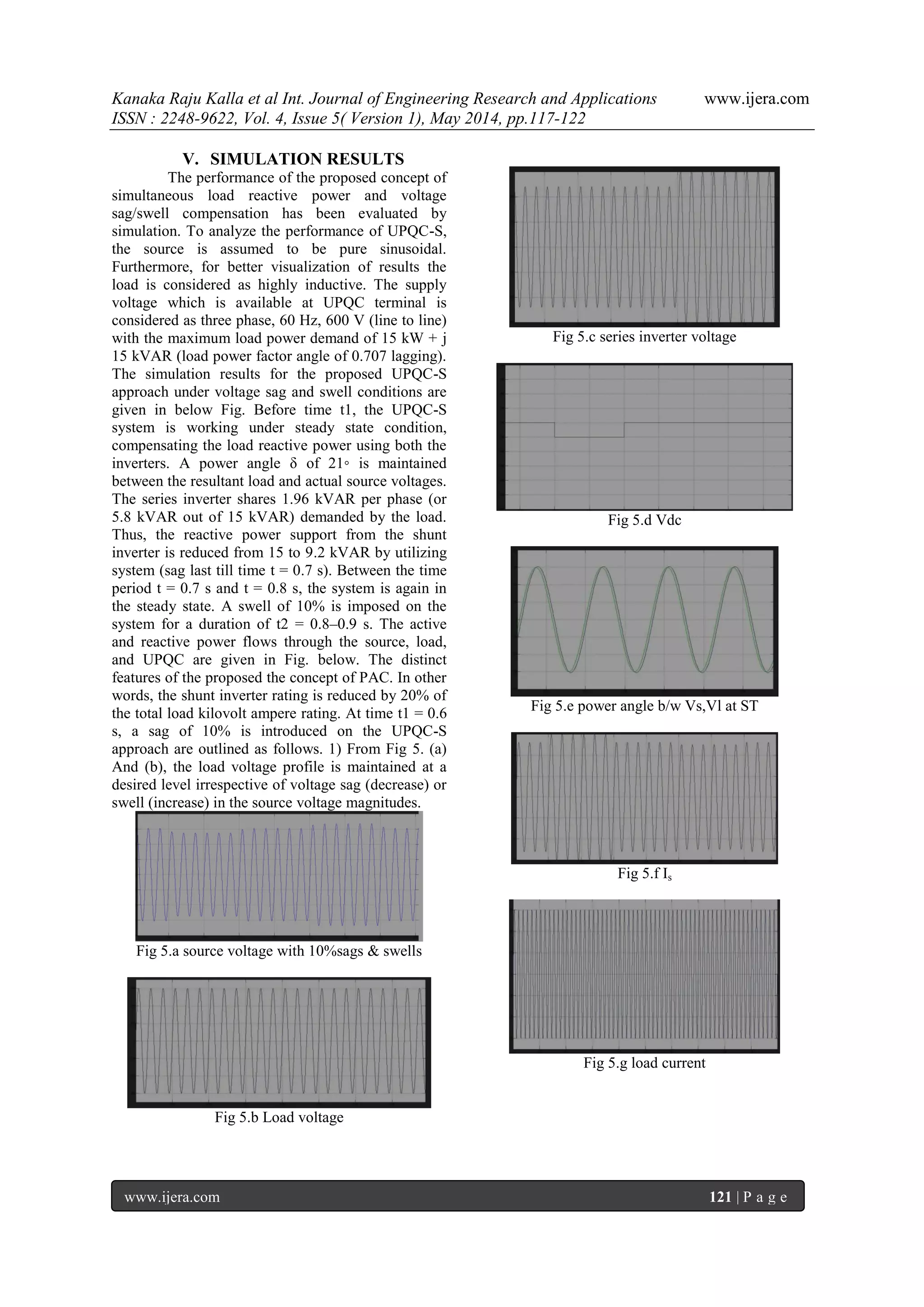
Fig 5.h Source active and reactive power
Fig 5.i series active power and reactive power
Fig 5.j shunt active and reactive power
VI. CONCLUSION
In this paper, a new concept of controlling
complex power (simultaneous active and reactive
powers) through series inverter of UPQC is
introduced and named as UPQC-S. The proposed
concept of the UPQC-S approach is mathematically
formulated and analyzed for voltage sag and swell
conditions. The developed comprehensive equations
for UPQC-S can be utilized to estimate the required
series injection voltage and the shunt compensating
current profiles (magnitude and phase angle), and the
overall VA loading both under voltage sag and swell
conditions. The simulation studies demonstrate the
effectiveness of the proposed concept of
simultaneous voltage sag/swell and load reactive
power sharing feature of series & shunt part of
UPQC-S with fuzzy logic controller. The significant
advantages of UPQC-S over general UPQC
applications are: 1) the multifunction ability of series
inverter to compensate voltage variation (sag, swell,
etc.) while supporting load reactive power; 2) better
utilization of series inverter rating of UPQC; and 3)
reduction in the shunt inverter rating due to the
reactive power sharing by both the inverters.
REFERENCES
[1] Vinod Khadkikar, and Ambrish Chandra
UPQC-S: A Novel Concept of Simultaneous
VoltageSag/Swell and Load Reactive Power
Compensations Utilizing Series Inverter of
UPQC.
[2] R. C. Dugan, M. F. McGranaghan, and H.
W. Beaty, Electrical Power Systems
Quality.. New York: McGraw-Hill, 1996, p.
265.
[3] C. Sankaran, Power Quality. Boca Raton,
FL: CRC Press, 2002, p. 202.
[4] R. A. Walling, R. Saint, R. C. Dugan, J.
Burke, and L. A. Kojovic, “Summary of
distributed resources impact on power
delivery systems,” IEEE Trans. Power Del.,
vol. 23, no. 3, pp. 1636–1644, Jul. 2008.
[5] L. Gyugyi, “Unified power-flow control
concept for flexible AC transmission
systems,” IEE – C Gene. Trans. Distr., vol.
139, no. 4, pp. 323–331, Jul. 1992.
[6] N. G. Hingorani and L. Gyugyi,
Understanding FACTS: Concepts and
Technology of Flexible AC Transmission
Systems. New York: IEEE Press, 2000, p.
432.
[7] V. K. Sood, HVDC and FACTS Controllers
– Applications of Static Converters in Power
Systems. Boston, MA: Kluwer, 2004, p. 295.
Power Electron. vol. 13, no. 2, pp. 315–322,
Mar. 1998.](https://image.slidesharecdn.com/u4501117122-140716024901-phpapp01/75/U4501117122-6-2048.jpg)

This paper introduces a new methodology called UPQC-S that utilizes a Unified Power Quality Conditioner (UPQC) with a fuzzy logic controller to enhance voltage quality, addressing issues such as voltage sags, harmonic distortions, and low power factors in distribution systems. The UPQC-S framework allows for simultaneous compensation of voltage variations and load reactive power sharing, validated through simulations. Key advantages include improved efficiency in inverter usage and reduced ratings for the shunt inverter due to collaborative power management.