Preliminary topics for Statics of Rigid Bodies.pdf
1.
Statics of RigidBodies
Prepared by: Franklin Joven Pasilbas, RCE
Lecture 1:
• Introduction
• Resultant of force system (coplanar)
2.
Introduction
Mechanics – isa branch of the physical sciences that is concerned with the state of rest or motion
of bodies that are subjected to action of forces.
Engineering Mechanics – is the branch of engineering that applies the principles of mechanics to
any design that must take in to account the effect of forces. The primary goal of engineering
mechanics courses is to introduce the student to the engineering applications of mechanics.
• Statics of Rigid Body
• Dynamics of Rigid Body
• Mechanics of Deformable Bodies
Rigid Body – definite amount of matter that is fixed.
Forces – anything that causes change to the rigid body.
3.
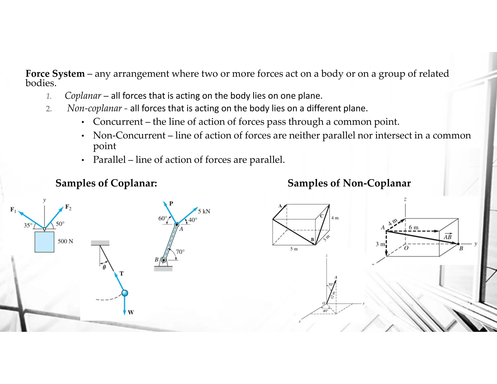
Force System –any arrangement where two or more forces act on a body or on a group of related
bodies.
1. Coplanar – all forces that is acting on the body lies on one plane.
2. Non-coplanar - all forces that is acting on the body lies on a different plane.
• Concurrent – the line of action of forces pass through a common point.
• Non-Concurrent – line of action of forces are neither parallel nor intersect in a common
point
• Parallel – line of action of forces are parallel.
Samples of Coplanar: Samples of Non-Coplanar
v
4.
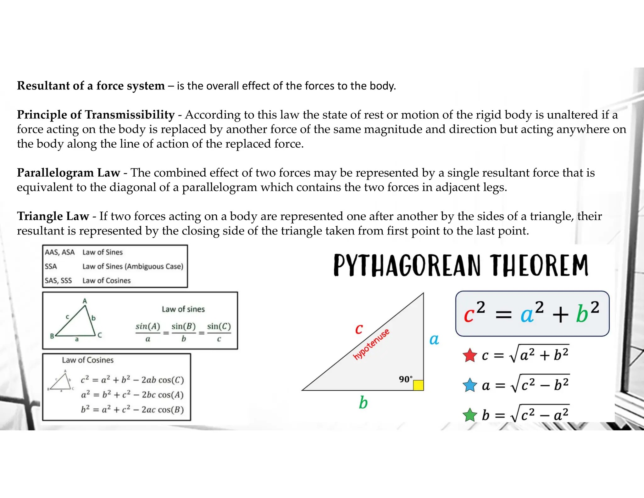
Resultant of aforce system – is the overall effect of the forces to the body.
Principle of Transmissibility - According to this law the state of rest or motion of the rigid body is unaltered if a
force acting on the body is replaced by another force of the same magnitude and direction but acting anywhere on
the body along the line of action of the replaced force.
Parallelogram Law - The combined effect of two forces may be represented by a single resultant force that is
equivalent to the diagonal of a parallelogram which contains the two forces in adjacent legs.
Triangle Law - If two forces acting on a body are represented one after another by the sides of a triangle, their
resultant is represented by the closing side of the triangle taken from first point to the last point.
5.
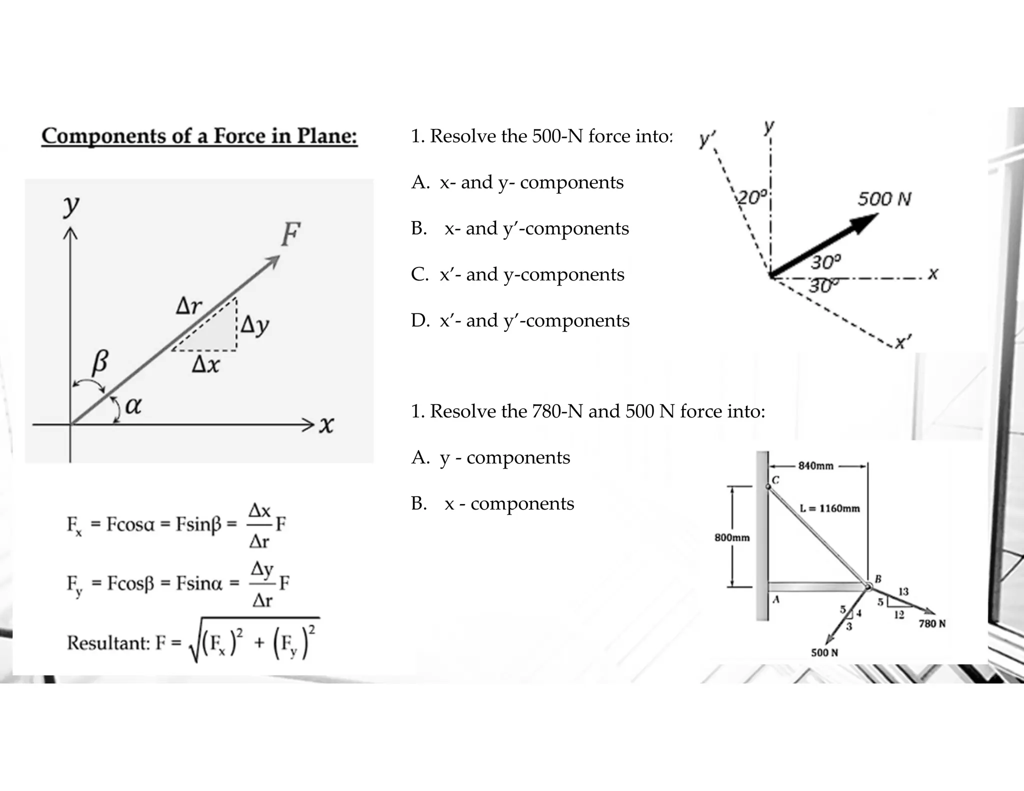
1. Resolve the500-N force into:
A. x- and y- components
B. x- and y’-components
C. x’- and y-components
D. x’- and y’-components
1. Resolve the 780-N and 500 N force into:
A. y - components
B. x - components
6.
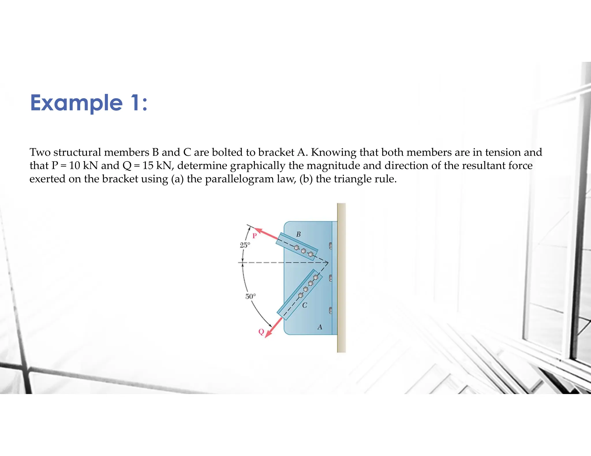
Two structural membersB and C are bolted to bracket A. Knowing that both members are in tension and
that P = 10 kN and Q = 15 kN, determine graphically the magnitude and direction of the resultant force
exerted on the bracket using (a) the parallelogram law, (b) the triangle rule.
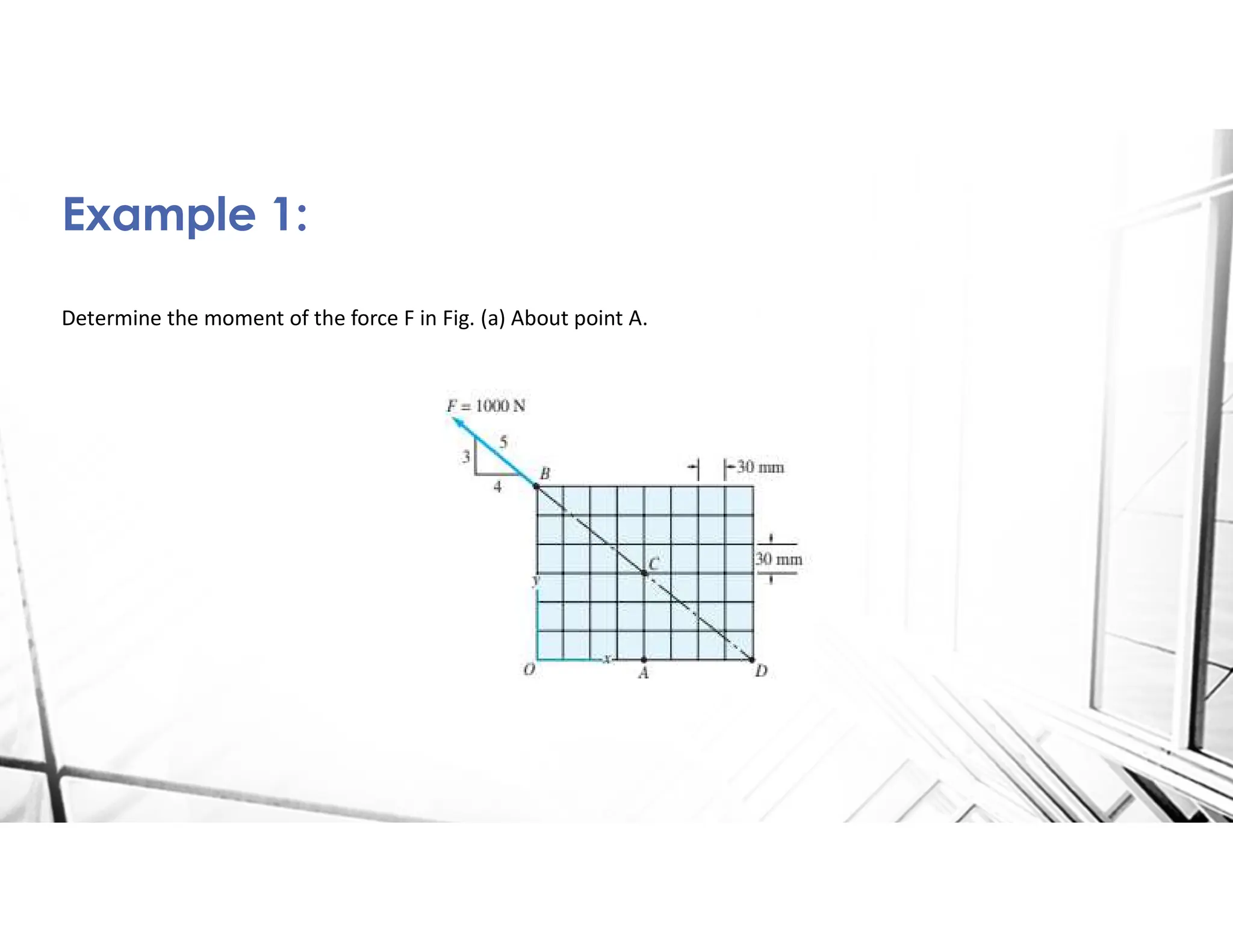
Example 1:
7.
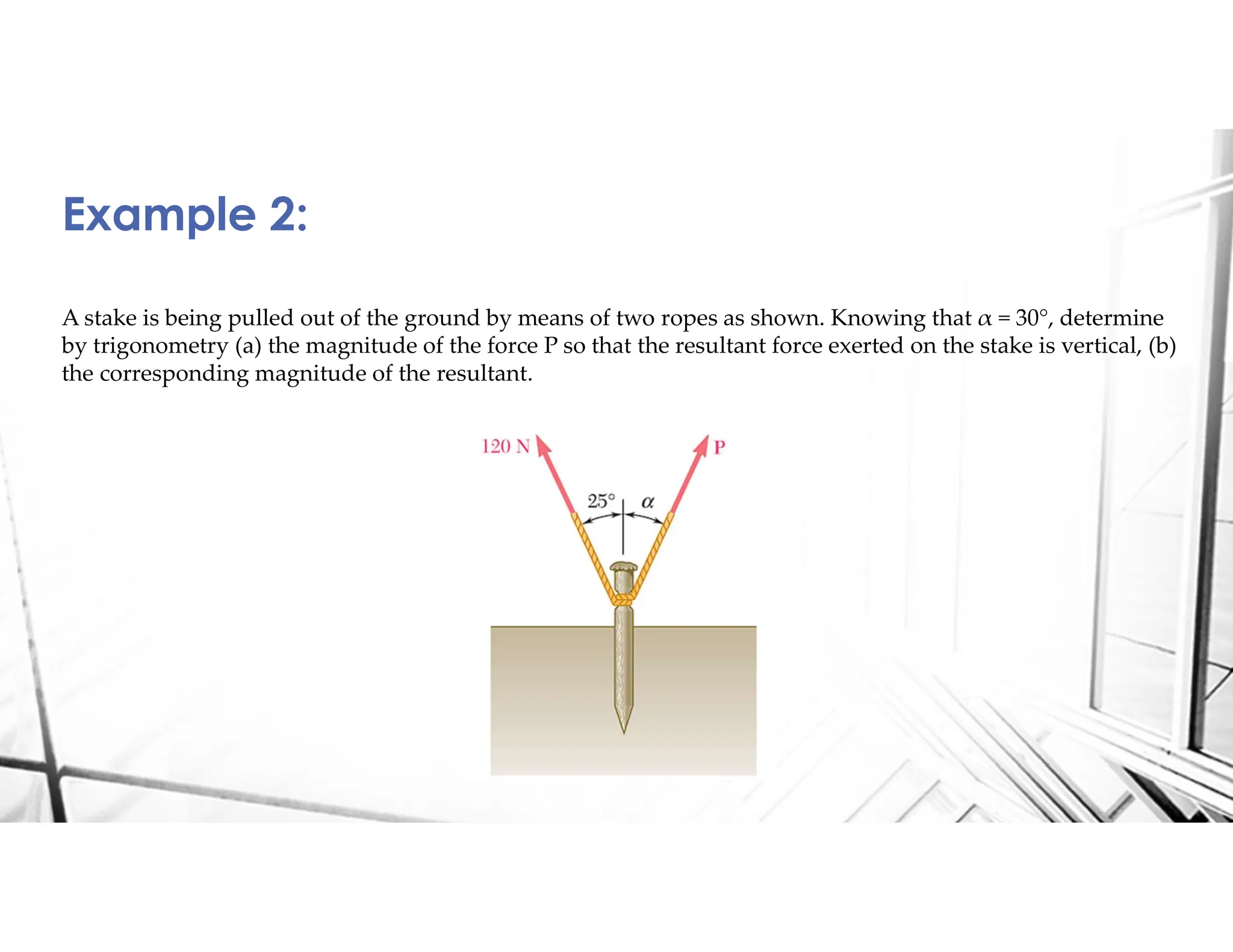
A stake isbeing pulled out of the ground by means of two ropes as shown. Knowing that α = 30°, determine
by trigonometry (a) the magnitude of the force P so that the resultant force exerted on the stake is vertical, (b)
the corresponding magnitude of the resultant.
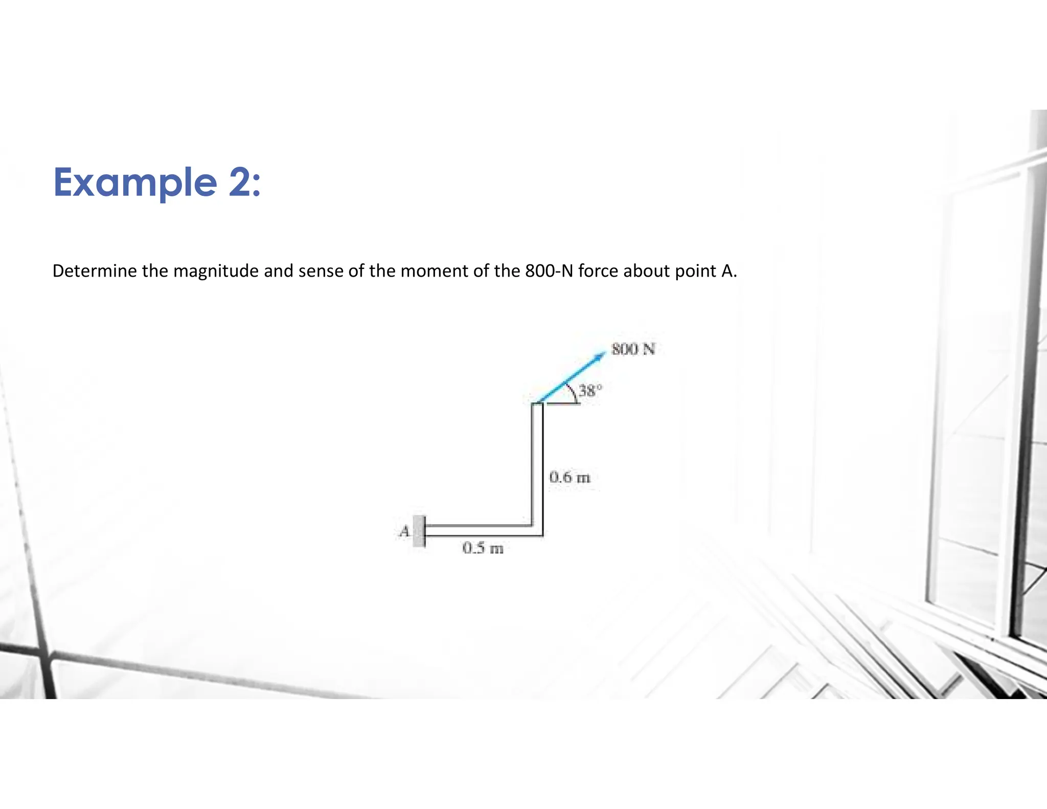
Example 2:
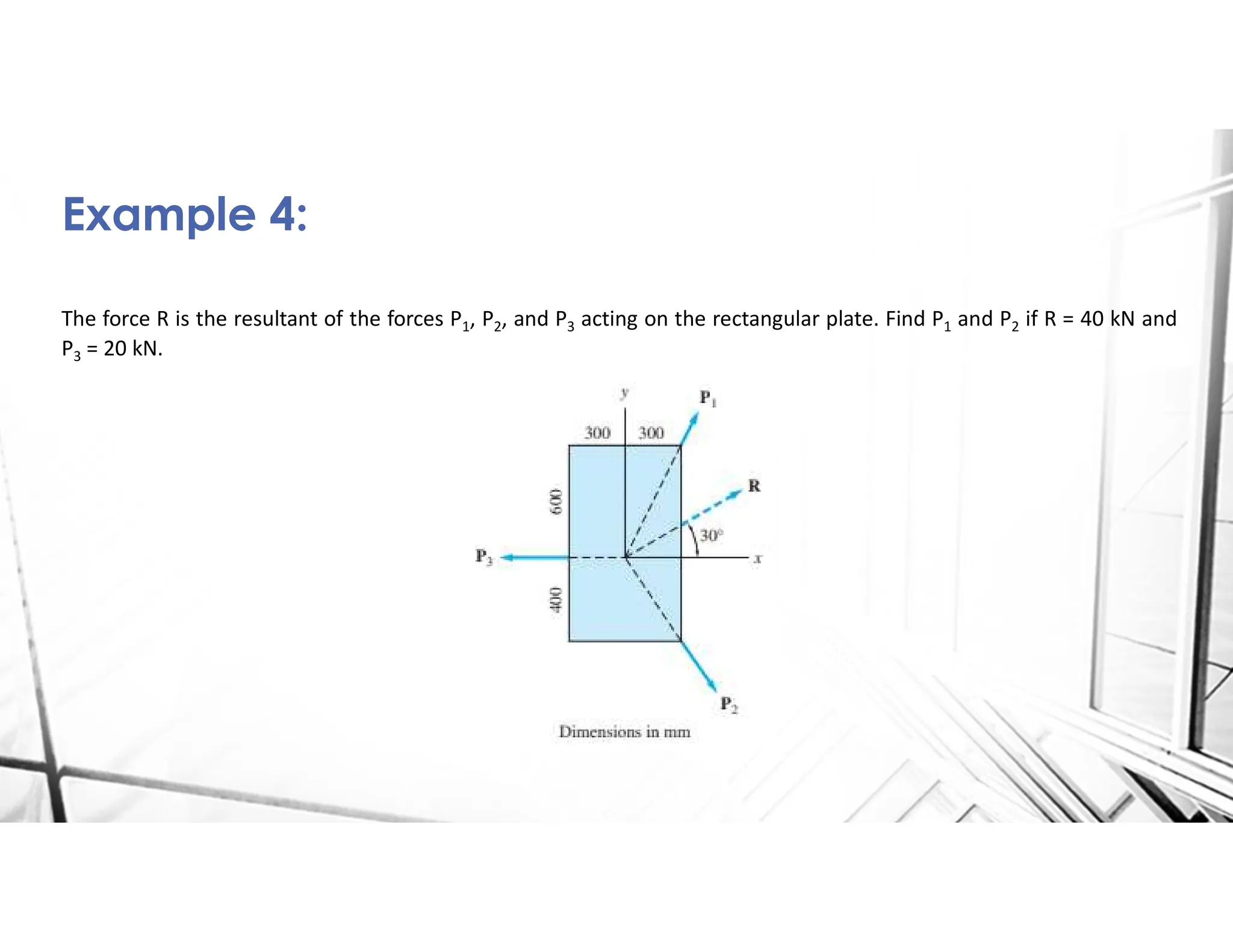
The force Ris the resultant of the forces P1, P2, and P3 acting on the rectangular plate. Find P1 and P2 if R = 40 kN and
P3 = 20 kN.
Example 4:
10.
Statics of RigidBodies
Prepared by: Franklin Joven Pasilbas, RCE
Lecture 2:
• Moment
• Couples
11.
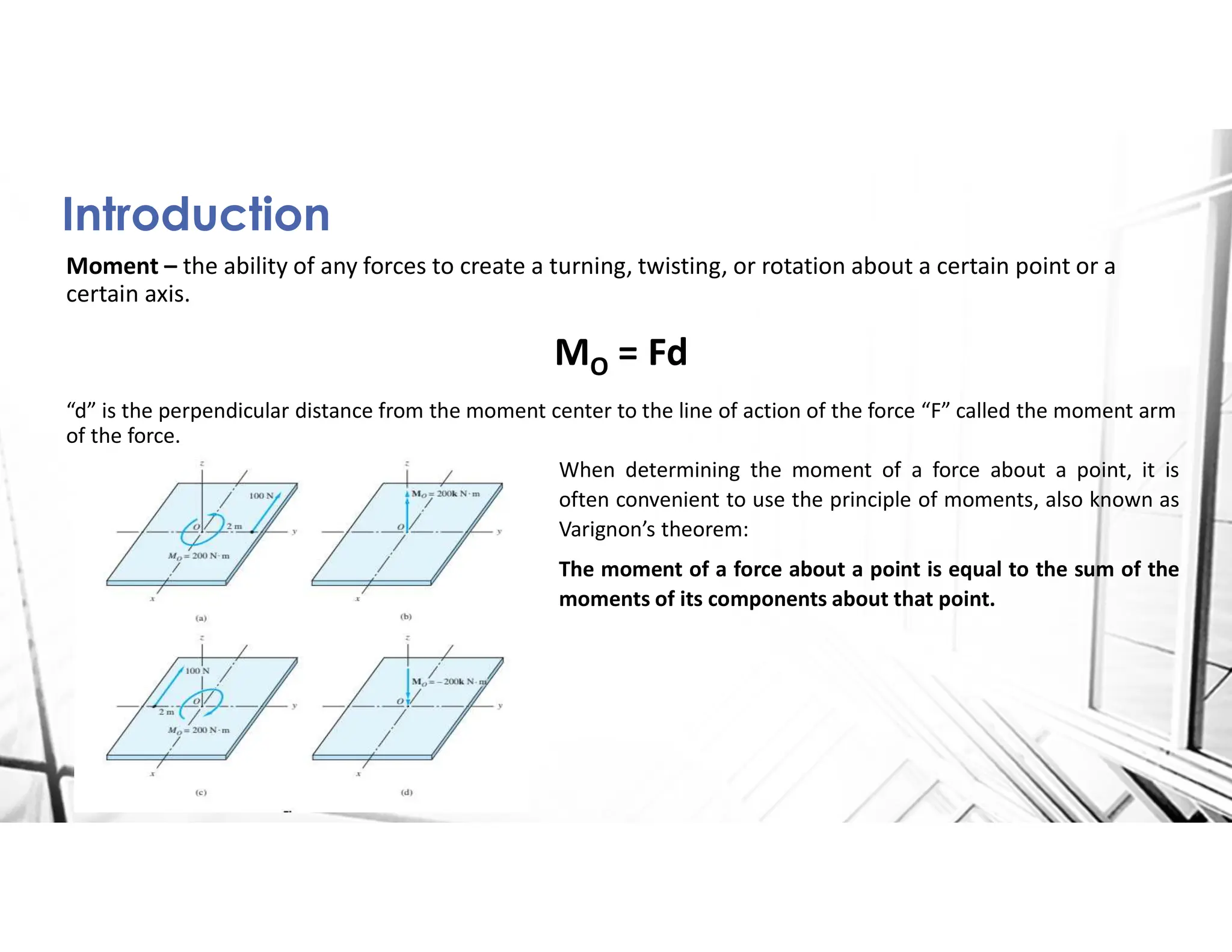
Introduction
Moment – theability of any forces to create a turning, twisting, or rotation about a certain point or a
certain axis.
MO = Fd
“d” is the perpendicular distance from the moment center to the line of action of the force “F” called the moment arm
of the force.
When determining the moment of a force about a point, it is
often convenient to use the principle of moments, also known as
Varignon’s theorem:
The moment of a force about a point is equal to the sum of the
moments of its components about that point.
12.
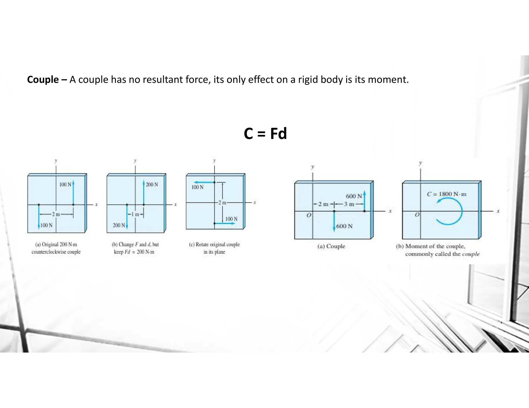
Couple – Acouple has no resultant force, its only effect on a rigid body is its moment.
C = Fd
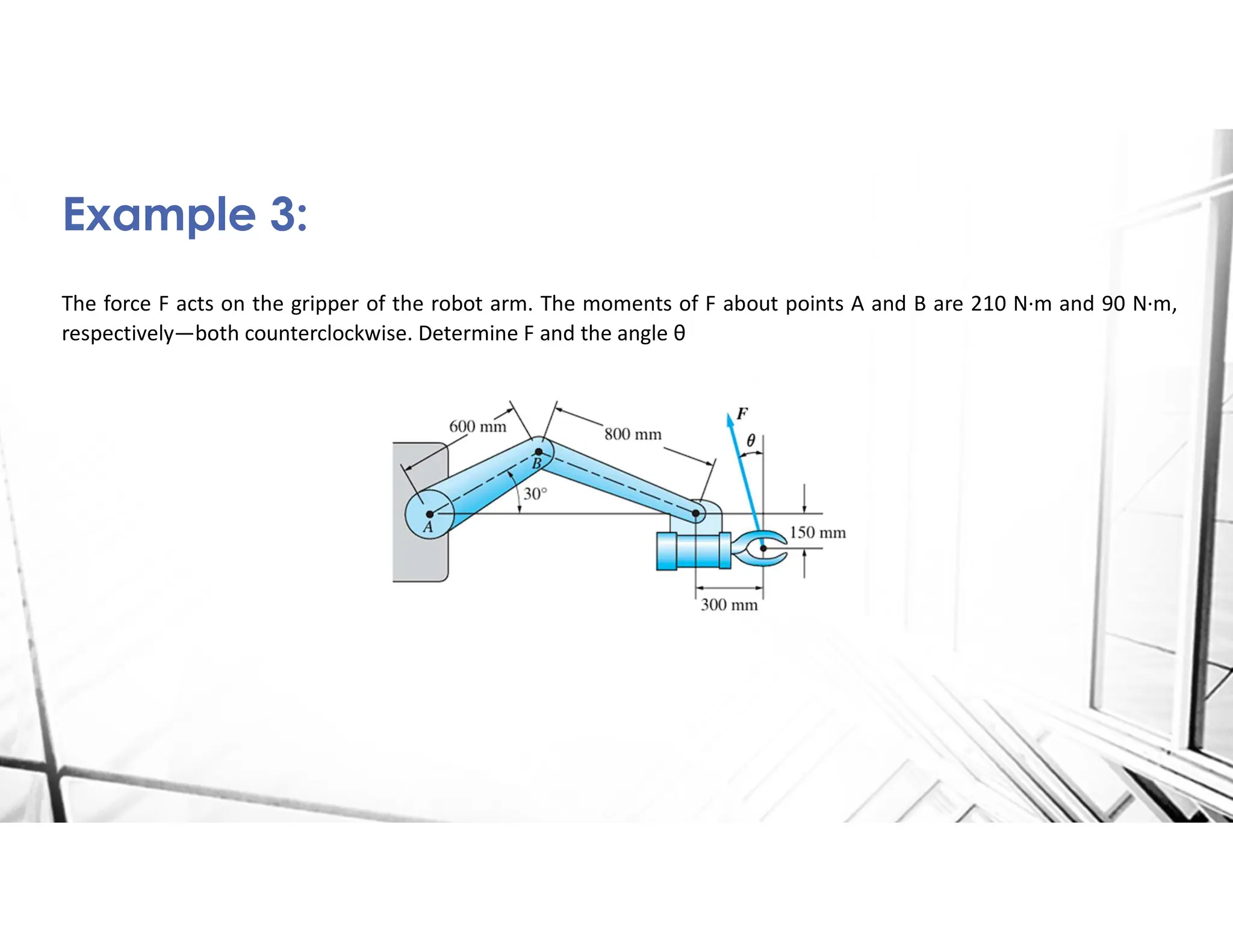
The force Facts on the gripper of the robot arm. The moments of F about points A and B are 210 N·m and 90 N·m,
respectively—both counterclockwise. Determine F and the angle θ
Example 3:
16.
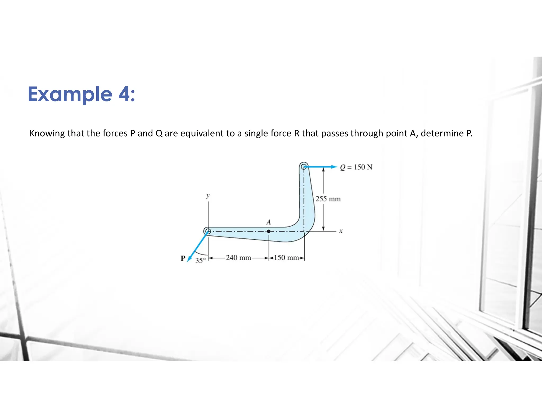
Knowing that theforces P and Q are equivalent to a single force R that passes through point A, determine P.
Example 4:
17.
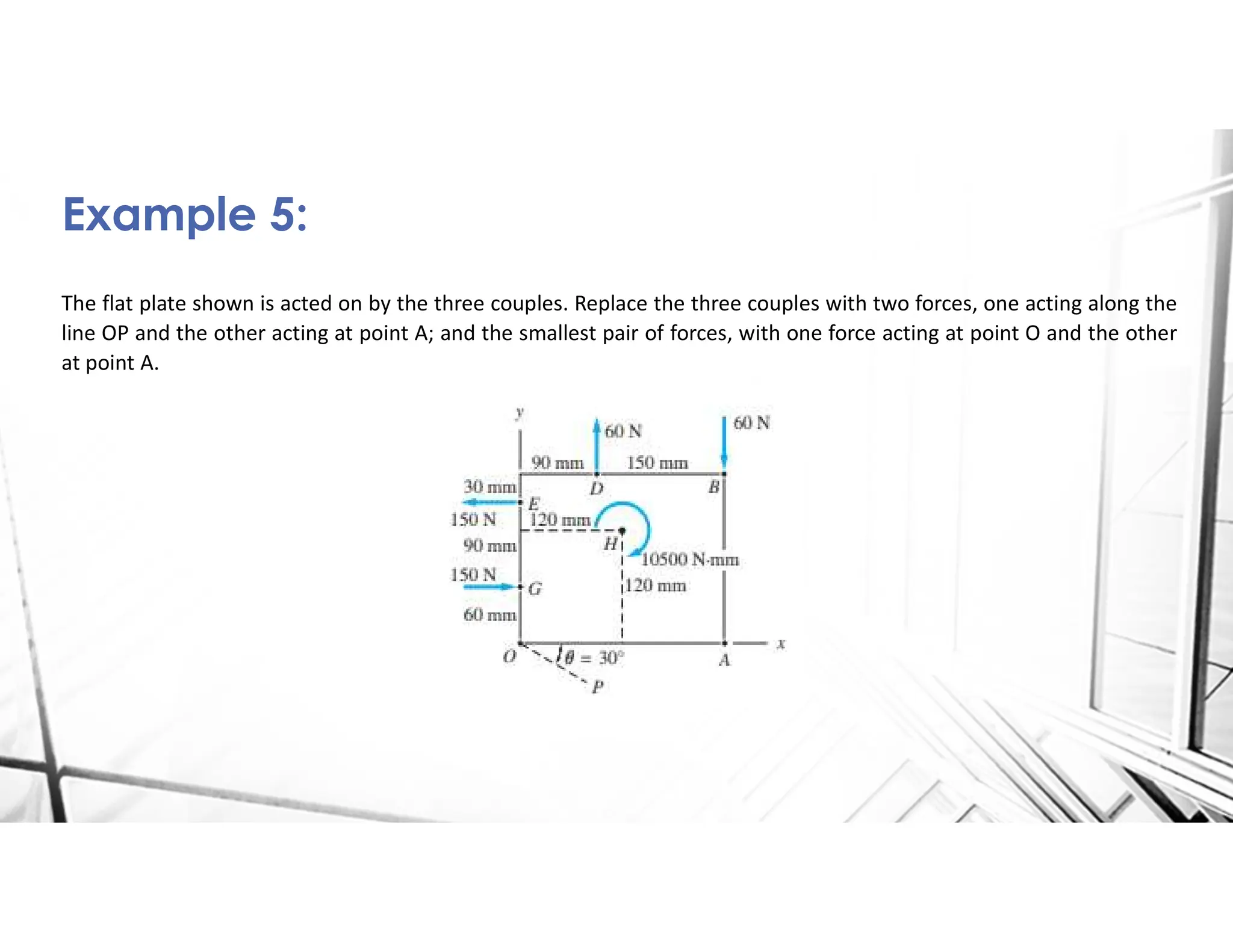
The flat plateshown is acted on by the three couples. Replace the three couples with two forces, one acting along the
line OP and the other acting at point A; and the smallest pair of forces, with one force acting at point O and the other
at point A.
Example 5:
18.
Statics of RigidBodies
Prepared by: Franklin Joven Pasilbas, RCE
Lecture 3:
• Resultant of Parallel force system
• Resultant of Non-concurrent force system
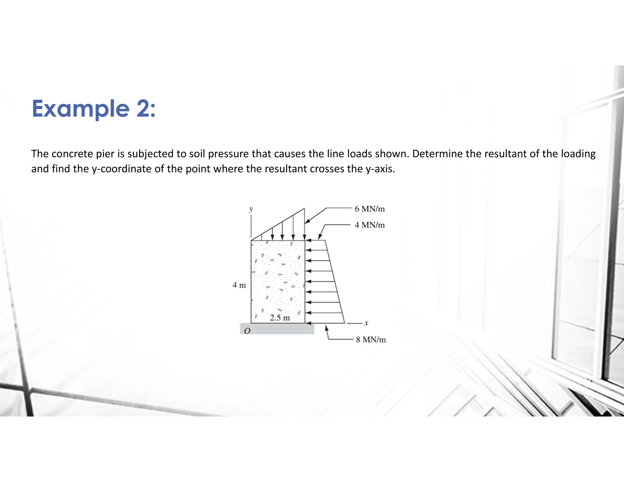
The concrete pieris subjected to soil pressure that causes the line loads shown. Determine the resultant of the loading
and find the y-coordinate of the point where the resultant crosses the y-axis.
Example 2:
22.
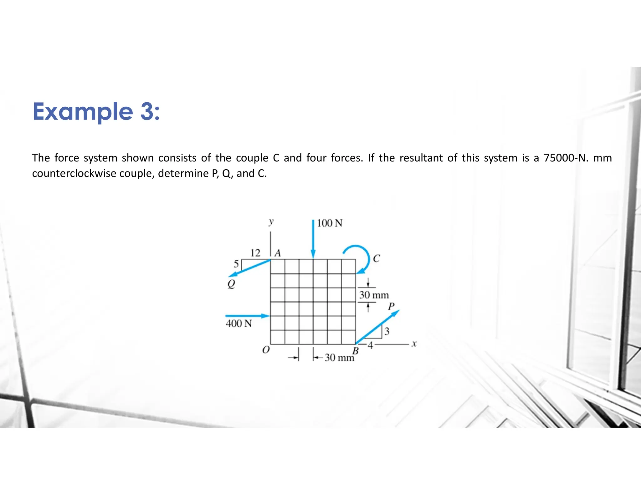
The force systemshown consists of the couple C and four forces. If the resultant of this system is a 75000-N. mm
counterclockwise couple, determine P, Q, and C.
Example 3:
23.
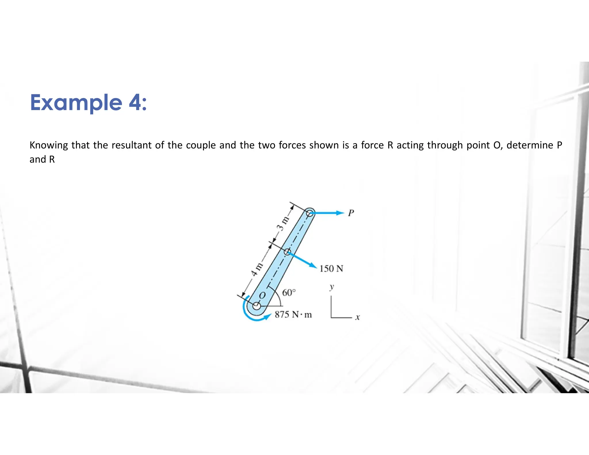
Knowing that theresultant of the couple and the two forces shown is a force R acting through point O, determine P
and R
Example 4:
24.
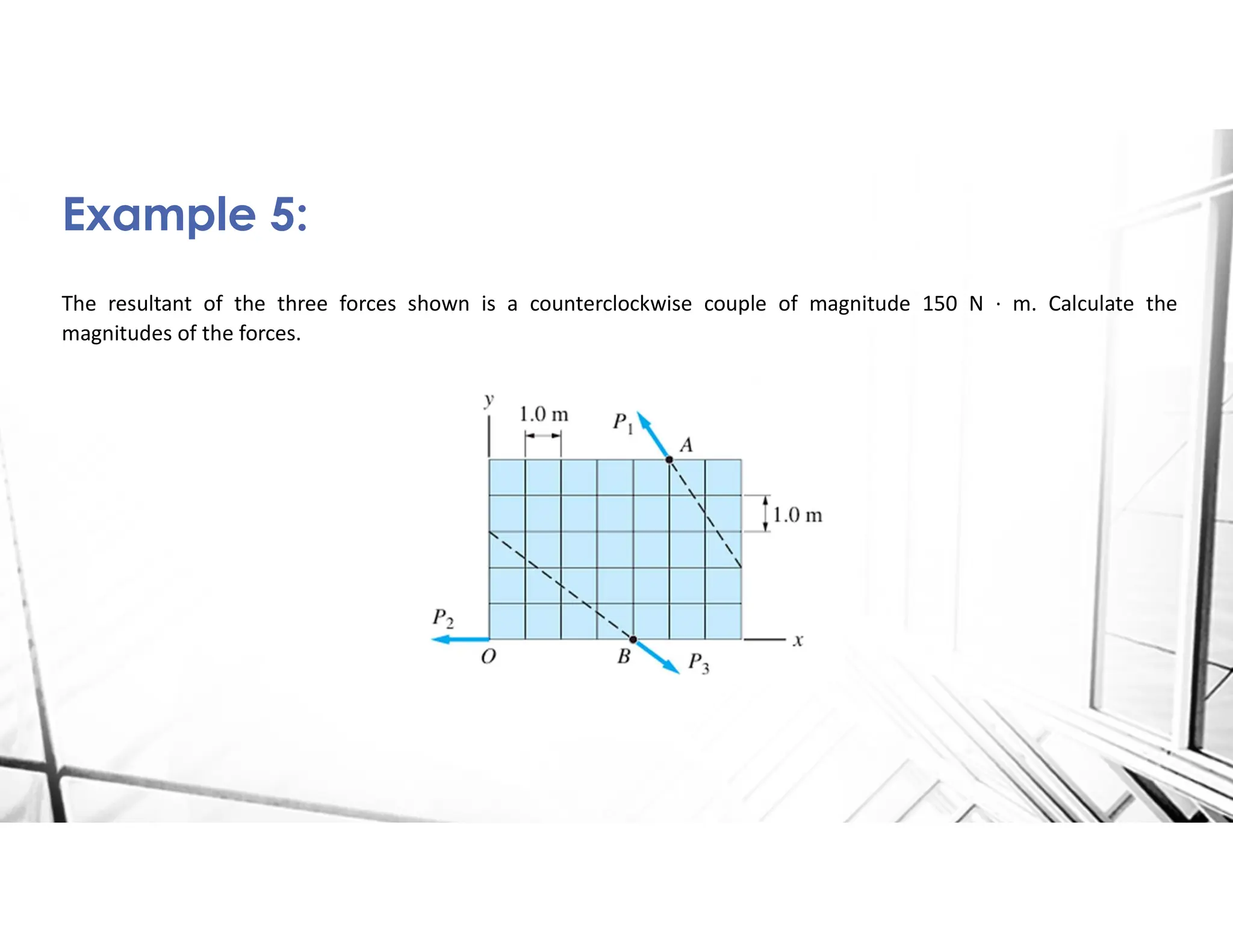
The resultant ofthe three forces shown is a counterclockwise couple of magnitude 150 N · m. Calculate the
magnitudes of the forces.
Example 5:
25.
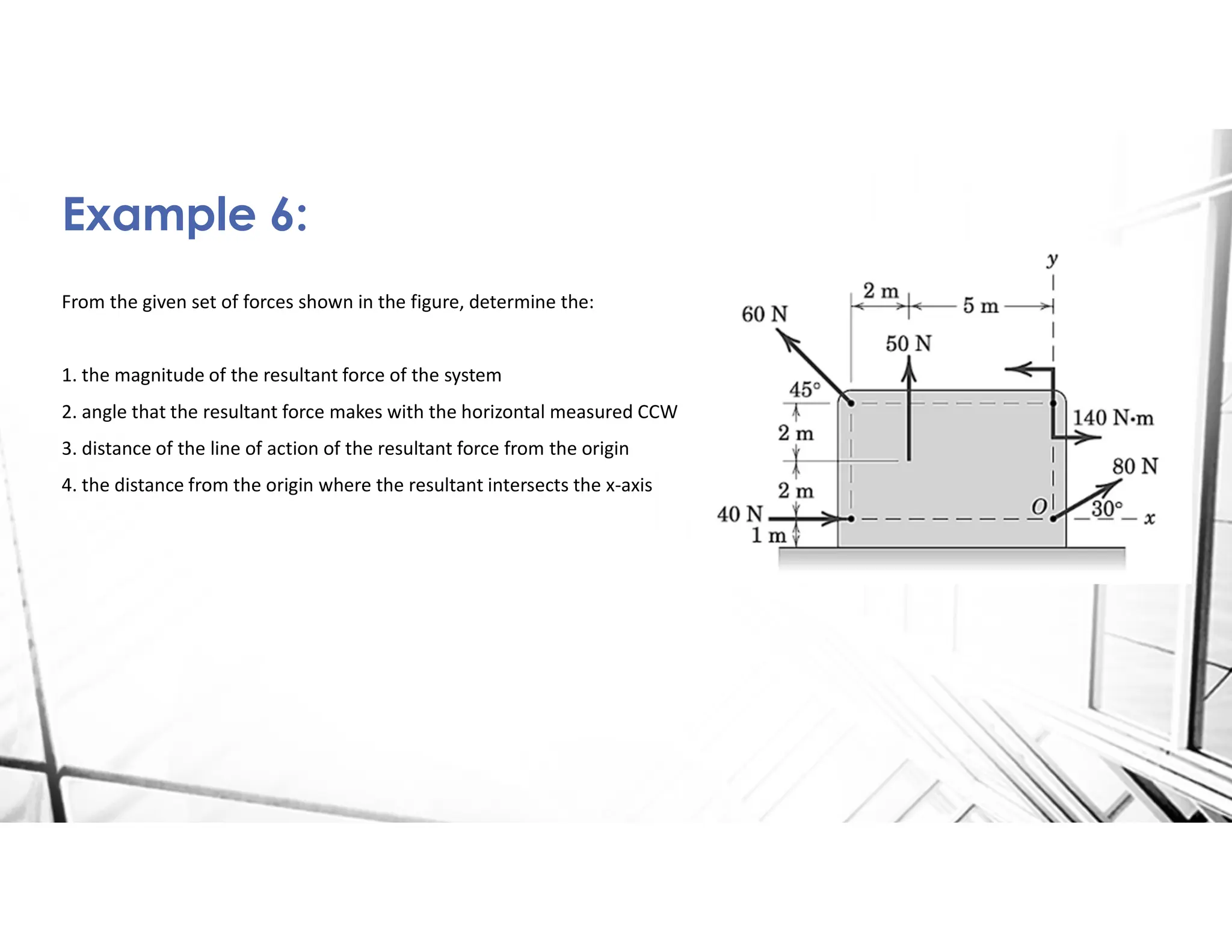
From the givenset of forces shown in the figure, determine the:
1. the magnitude of the resultant force of the system
2. angle that the resultant force makes with the horizontal measured CCW
3. distance of the line of action of the resultant force from the origin
4. the distance from the origin where the resultant intersects the x-axis
Example 6:


![Ctm 154[1]](https://cdn.slidesharecdn.com/ss_thumbnails/ctm1541-190506153756-thumbnail.jpg?width=640&height=640&fit=bounds)


