This document discusses force vectors and their representation. It covers key topics such as:
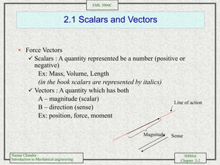
- Scalars and vectors, and examples of each
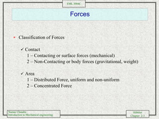
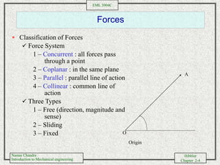
- Classifying forces as distributed or concentrated, and contact or body forces
- Representing the direction and magnitude of a force vector using unit vectors
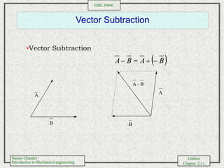
- Performing vector addition and subtraction of forces using trigonometric relationships and Cartesian components
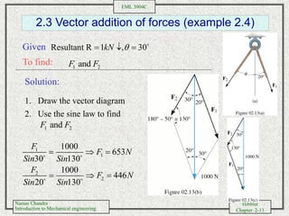
- Solving examples of adding and subtracting forces to determine the resultant force vector