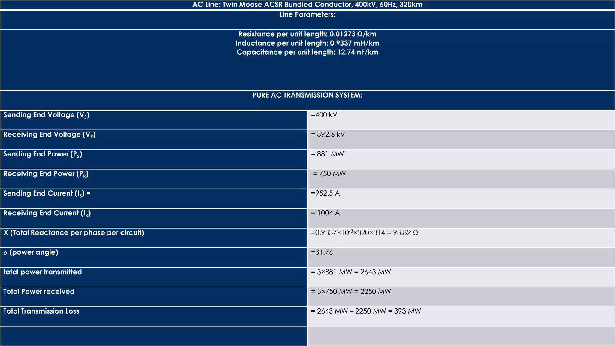
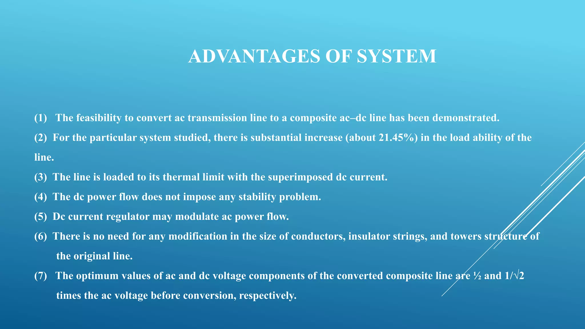
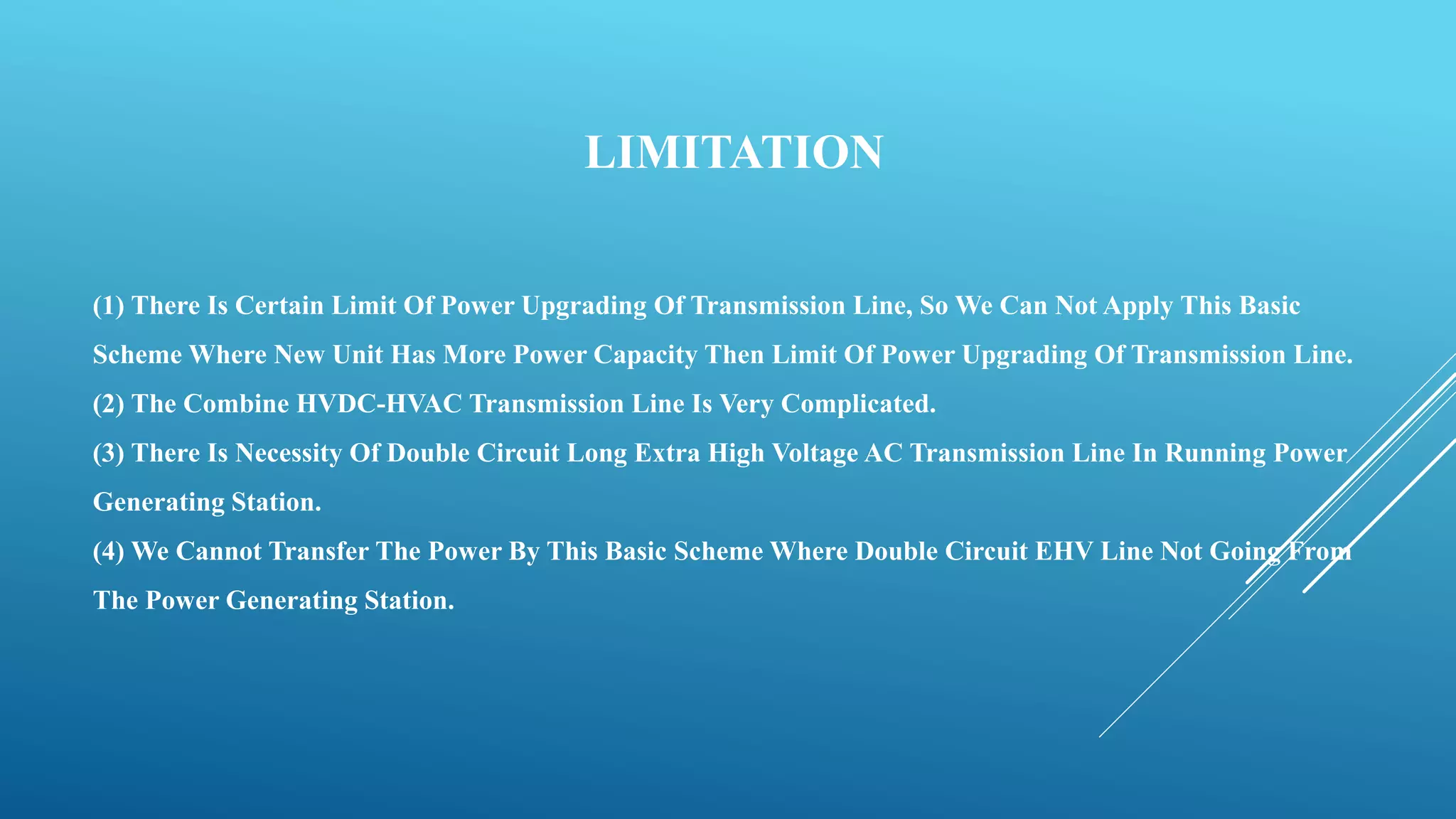
The document details a study on the integration of AC and DC transmission systems, highlighting theoretical proofs, MATLAB simulations, and economic assessments of the combined system. It demonstrates a 21% increase in load capacity without significant structural modifications and outlines both advantages and limitations. The conclusion emphasizes the independent flow of DC power and the practical applications for upgrading existing transmission lines.

![CONDITION OF TRANSMISSION
[1] VMAX = √𝟐Vph = Vd + √𝟐Va
[2]VLL MAX = √𝟔Va
[3] Vd= Vph/√𝟐
[4] Va = Vph/ 2](https://image.slidesharecdn.com/powerupgradingoftransmissionlinebycombiningac-dctransmission-150717200544-lva1-app6891/75/Power-upgrading-of-transmission-line-by-combining-ac-dc-transmission-6-2048.jpg)

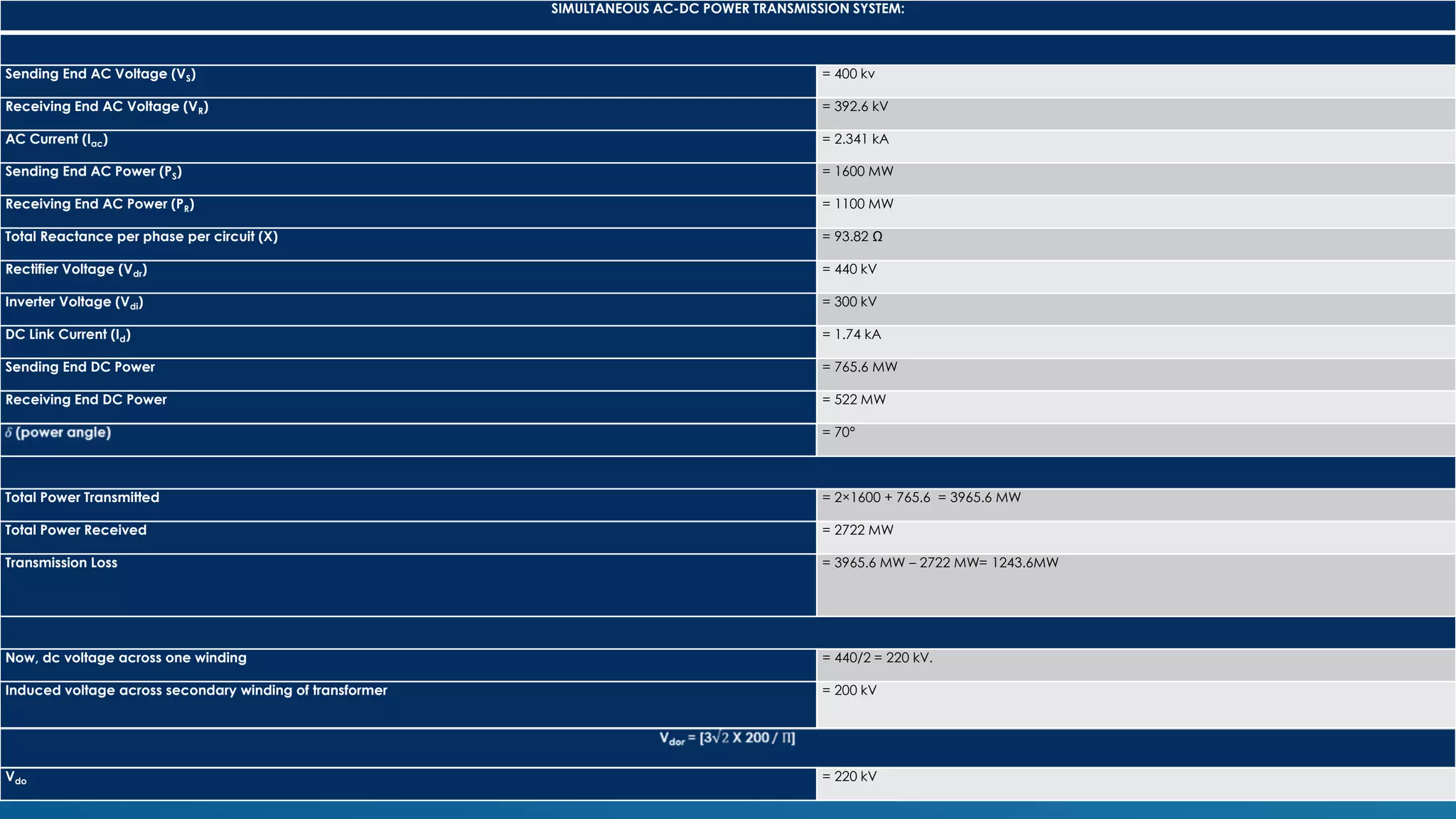
![So, power factor of the rectifier (cosθr) = 220/271 = 0.812
Similarly for inverter
Vdoi = 271 kV
Vdo = 150 kV
Power factor of the inverter (cosθi) = 150/271 = 0.5535
So, reactive power drawn by the rectifier = 765.6 tanθr = 550.3 MVAR
Reactive power drawn by the inverter = 522 tanθi = 785.45 MVAR
Power Up gradation =
Power transformer in composite AC – DC transmissions - power transmitted in pure transmission /
power transmitted in pure transmission
= [ 2722 – 2250 / 2250 ] Χ 100
= 21 %](https://image.slidesharecdn.com/powerupgradingoftransmissionlinebycombiningac-dctransmission-150717200544-lva1-app6891/75/Power-upgrading-of-transmission-line-by-combining-ac-dc-transmission-16-2048.jpg)

![ECONOMY OF THE SYSTEM
[1] ECONOMY OF SYSTEM BASED ON COMPARISON
[2] ECONOMY OF SYSTEM BASED ON STRUCTURE](https://image.slidesharecdn.com/powerupgradingoftransmissionlinebycombiningac-dctransmission-150717200544-lva1-app6891/75/Power-upgrading-of-transmission-line-by-combining-ac-dc-transmission-18-2048.jpg)
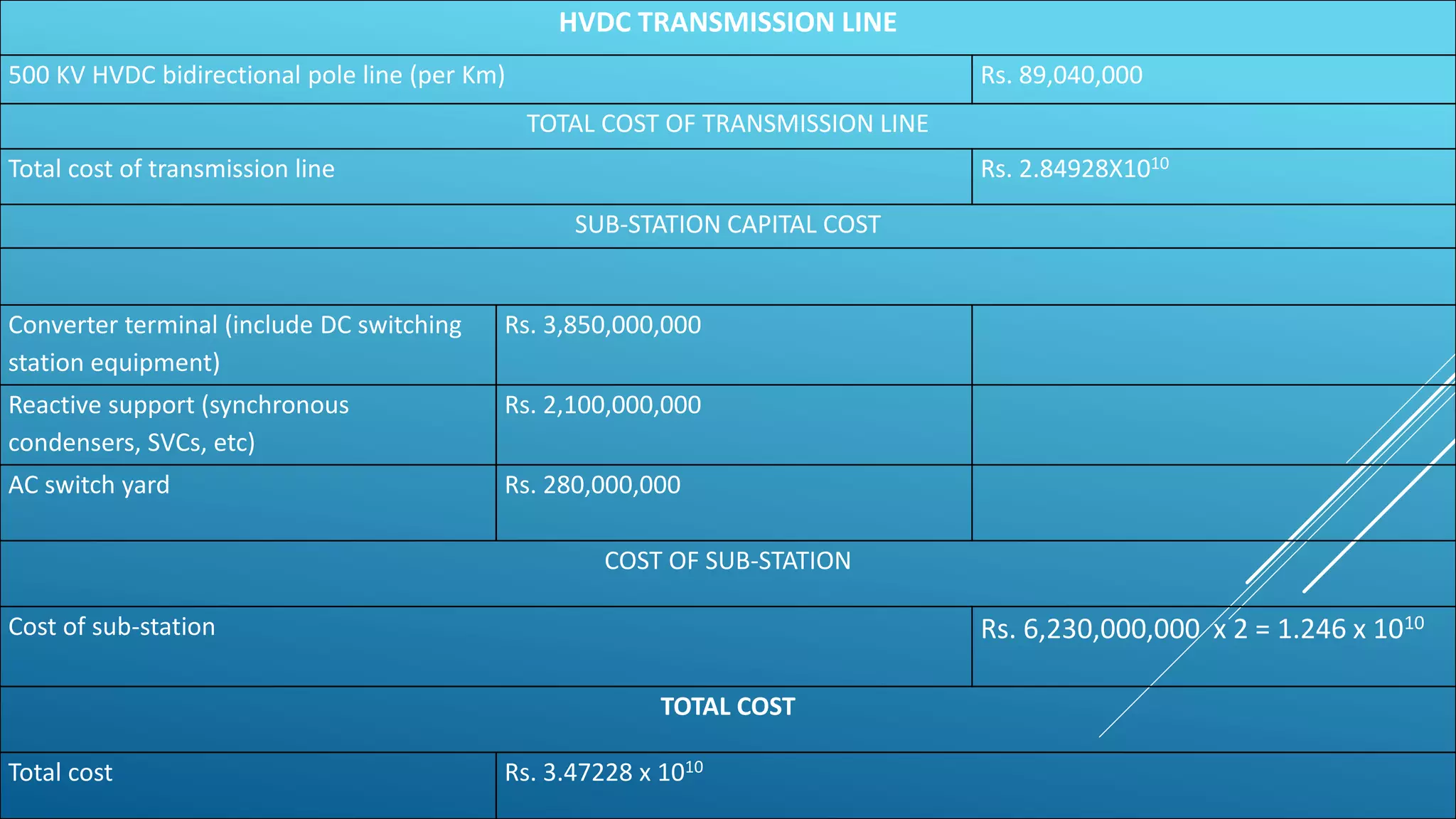
![FOR DOUBLE CIRCUIT EHV LINE
Base cost of 500 KV double circuit transmission line Rs. 1,78,020,000
Line Multiplier :
(1) Conductor
ACSR (1.0) √ ACSS (1.08) TLS (3.60)
(1) Tower Structure:
Lattice (1.0) √ Tabular Steel (1.50)
(1) Transmission Length:
Up to 4.82 Km (1.50) 4.82 Km to 16.093 Km (1.20) Above 16.093 Km (1.0) √
Total transmission line cost = [ (base transmission cost)*(conductor multiplier)*(structure multiplier) *(1.6093)*(no of kilometer) ]
Total transmission line cost Rs. 5.696641010
SUB-STATION CAPITAL COST
Base cost of Sub-Station (500 KV) Rs. 148,320,000
LINE & TRANSFORMER POSITION COST & MULTIPLIER (500 KV)
Cost multiplier : Breaker & half multiplier (1.50) Ring bus multiplier (1.0) √
Cost per line / transformer position Rs. 173,040,000
Transformer cost (Rs. per MVA)
230 / 500 KV Transformer – Rs. 660,000 115 / 500 KV Transformer – Rs. 600,000 √
Transformer cost (Rs. Per MVA) Rs. 600,000
REACTIVE COMPONENTS COST PER MVAR
Shunt reactor Rs. 1,200,000
Series reactor Rs. 600,000
SVC capital cost Rs. 5,100,000
Total substation cost = [ (sub-station base cost)+(line per transformer position base cost)*(no. of line per transformer position)*(CRB or BAAH
multiplier)+(transformer cost per MVA)*(transformer MVA rating)+(SVC cost per MVAR)*(require MVARs)+(series capacitor cost per
MVAR)*(require MVARs)+(shunt reactor cost per MVAR)*(require MVARs) ]
Total substation cost Rs. 839,052,000 x 2 = 1,678,104,000
TOTAL COST](https://image.slidesharecdn.com/powerupgradingoftransmissionlinebycombiningac-dctransmission-150717200544-lva1-app6891/75/Power-upgrading-of-transmission-line-by-combining-ac-dc-transmission-19-2048.jpg)
![REFERENCES
PAPERS:-
[1] “Upgradation Of Power Flow In EHV AC Transmission” International Journal Of Scientific Engineering And
Technology By K.K.Vasishta Kumar, K.Sathish Kumar.
[2] “Power Upgrading Of Transmission Line By Combining AC-DC Transmission”, Swarnandhra College Of Engineering
Technology Narsapur By Jarupula Somlal.
[3] “Power System Stability Enhancement By Simultaneous AC-DC Power Transmission” International Journal Of
Advanced Research In Electrical, Electronics And Instrumentation Engineering Vol. 2, Issue 5, May 2013 By Abhishek
Chaturvedi, V. K. Tripathi, T Vijay Muni, Neeraj Singh.
[4] “Power Tapping Of Upgrade Transmission Line By Using Composite Ac-dc Power Transmission Lines”
International Journal Of Engineering Research And Development By CH.Veeraiah, Y.Rambabu, V.K.R.Mohan Rao.](https://image.slidesharecdn.com/powerupgradingoftransmissionlinebycombiningac-dctransmission-150717200544-lva1-app6891/75/Power-upgrading-of-transmission-line-by-combining-ac-dc-transmission-28-2048.jpg)
![BOOKS:-
[1] D P Kothari And I J Nagrath “MODERN POWER SYSTEM ANALYSIS” FNAE Fnasc,
Fellow-ieee Director General, Raisoni Group Of Institutions, Nagpur.
[2] Tim Mason- Project Manager, Trevor Curry And Dan Wilson, “CAPITAL COSTS FOR
TRANSMISSION AND SUBSTATION” Western Electricity Coordinating Council.
[3] Roberto Rudervall, J.P. Charpentier And Raghuveer Sharma, “HIGH VOLTAGE DIRECT
CURRENT (HVDC)TRANSMISSION SYSTEMS” Technology Review Paper, Presented At Energy
Week 2000, Washington, D.C, USA, March 7-8, 2000.](https://image.slidesharecdn.com/powerupgradingoftransmissionlinebycombiningac-dctransmission-150717200544-lva1-app6891/75/Power-upgrading-of-transmission-line-by-combining-ac-dc-transmission-29-2048.jpg)