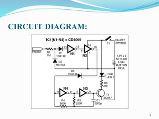
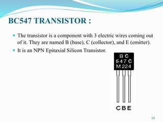
-by
G.SRAVAN
(12J21A0431)
1
INTRODUCTION
 In our day to day life we use various electronic appliances
employing various complex components in there circuitry and
in the present era everyone is over dependent on electronic
gadgets.
 Due to prolonged usage, the power cord wires are subjected to
mechanical strain and stress, which can lead to internal
snapping of wires at any point.
 So we have built a circuit which can easily detect the exact
location of the broken wire and thus reduces unnecessary
expenses of the user.
2
CIRCUIT DIAGRAM:
3
OPERATION :
 It is built using hex inverter CMOS CD4069. Gates N3 and
N4 are used as a pulse generator that oscillates at around
1000 Hz in audio range.
 The frequency is determined by timing components
comprising resistors R3 and R4 and capacitor C1.
 To detect the breakage point, turn on switch S1 and slowly
move the test probe closer to the faulty wire, beginning with
the input point of the live wire and proceeding towards its
other end.
4
COMPONENTS USED :
CMOS HEX INVERTER CD 4069 :
 The CD4069UB consists of six inverter circuits and is
manufactured using complementary MOS (CMOS) to achieve
wide power supply operating range, low power consumption,
high noise immunity, and symmetric controlled rise and fall
times.
5
INTERNAL DIAGRAM OF CD 4069 :
6
FEATURES :
 Wide supply voltage range: 3.0V to 15V
 High noise immunity: 0.45 VDD type
 Low power TTL compatibility: Fan out of 2 driving 74L
 Operating Temperature Range (TA) −55°C to +125°C
7
1N4148 diodes
High Speed switching.
8
FEATURES :
 High switching speed: max. 4 ns
 General application
 Continuous reverse voltage: max. 100 V
 Repetitive peak reverse voltage: max.100V
 Repetitive peak forward current: max. 450 mA.
9
BC547 TRANSISTOR :
 The transistor is a component with 3 electric wires coming out
of it. They are named B (base), C (collector), and E (emitter).
 It is an NPN Epitaxial Silicon Transistor.
10
Types of resistors used in the Circuit
 47 ohm Resistor
 1M ohm Resistor
 560 ohm Resistor
 220 ohm Resistor
11
CONCLUSION
 Thus the circuit was made successfully which can easily detect
broken point in the wire inside the PVC jacket without
physically disturbing it.
 This will make the circuit more compact and easy to handle.
 The handy broken-wire detector can be taken anywhere and
everywhere and becomes less prone to damage.
12
Any Queries?
13
14

Invisible wire

  • 1.
  • 2.
    INTRODUCTION  In ourday to day life we use various electronic appliances employing various complex components in there circuitry and in the present era everyone is over dependent on electronic gadgets.  Due to prolonged usage, the power cord wires are subjected to mechanical strain and stress, which can lead to internal snapping of wires at any point.  So we have built a circuit which can easily detect the exact location of the broken wire and thus reduces unnecessary expenses of the user. 2
  • 3.
  • 4.
    OPERATION :  Itis built using hex inverter CMOS CD4069. Gates N3 and N4 are used as a pulse generator that oscillates at around 1000 Hz in audio range.  The frequency is determined by timing components comprising resistors R3 and R4 and capacitor C1.  To detect the breakage point, turn on switch S1 and slowly move the test probe closer to the faulty wire, beginning with the input point of the live wire and proceeding towards its other end. 4
  • 5.
    COMPONENTS USED : CMOSHEX INVERTER CD 4069 :  The CD4069UB consists of six inverter circuits and is manufactured using complementary MOS (CMOS) to achieve wide power supply operating range, low power consumption, high noise immunity, and symmetric controlled rise and fall times. 5
  • 6.
  • 7.
    FEATURES :  Widesupply voltage range: 3.0V to 15V  High noise immunity: 0.45 VDD type  Low power TTL compatibility: Fan out of 2 driving 74L  Operating Temperature Range (TA) −55°C to +125°C 7
  • 8.
  • 9.
    FEATURES :  Highswitching speed: max. 4 ns  General application  Continuous reverse voltage: max. 100 V  Repetitive peak reverse voltage: max.100V  Repetitive peak forward current: max. 450 mA. 9
  • 10.
    BC547 TRANSISTOR : The transistor is a component with 3 electric wires coming out of it. They are named B (base), C (collector), and E (emitter).  It is an NPN Epitaxial Silicon Transistor. 10
  • 11.
    Types of resistorsused in the Circuit  47 ohm Resistor  1M ohm Resistor  560 ohm Resistor  220 ohm Resistor 11
  • 12.
    CONCLUSION  Thus thecircuit was made successfully which can easily detect broken point in the wire inside the PVC jacket without physically disturbing it.  This will make the circuit more compact and easy to handle.  The handy broken-wire detector can be taken anywhere and everywhere and becomes less prone to damage. 12
  • 13.
  • 14.