Downloaded 19 times


![Fixed cable (e.g., in-, on-, or behind-the-wall cables)
Region or
country
Phases Neutral
Protective
earth/ground
Argentina; China;
European Union
(IEC 60446) from
April 2004; the
United Kingdom
from 31 March
2004 (BS 7671);
Hong Kong from
July 2007;
Singapore from
March 2009;
Russia since 2009
(GOST R 50462);
Ukraine, Belarus,
Kazakhstan
,
,
[b]
India, Pakistan;
United Kingdom,
prior to 31 March
2004 (BS 7671);
Hong Kong, prior
to 2009; Malaysia
and Singapore,
prior to February
2011
,
,
[b]
(previously)
no
insulation (previously)
Australia, New
Zealand (AS/NZS
3000:2007 3.8.1,
table 3.4)
,
,[c]
,
, prohibited; any
other color permitted
,
recommended for single phase
,
, recommended for
multiphase
,[c]
(since
about 1980 - Stranded
Wire)
(since
about 1966 - Stranded
Wire)
Stranded
Wire - no insulation;
sleeved at the ends
(previously)[d]
Brazil
,
, ,
South Africa
, ; or
,
[b]
United States[e]
,
, for 120, 208, or
240 V
for
120, 208, or
240 V
no
insulation](https://image.slidesharecdn.com/electricalwiring-161122062021/85/Electrical-wiring-6-320.jpg)
![,
, for 277, or 480 V
metallic brass
for
277, or 480 V
metallic silver
required
for isolated systems
Canada[6][e]
, for
single-phase systems
,
, for three-phase
systems
,
,
no
insulation
, for
isolated single-phase systems
,
, for isolated three-
phase systems
, for
isolated systems
Boxes (e.g., translucent purple) denote markings on wiring terminals.
1. Jump up^ The colours in this table represent the most common and preferred standard colours for w iring;
how ever others may be in use, especially in older installations.
2. ^ Jump up to:a b c
Cables may have an uninsulated PE w hich is sleeved w ith the appropriate identifying
colours at both ends, especially in the UK.
3. ^ Jump up to:a b
Australian and New Zealand w iring standards allow both European and Australian colour
codes. Australian-standard phase colours conflict w ith IEC 60446 colours, w here IEC-60446
supported neutral colour (blue) is an allow ed phase colour in the Australia/New Zealand standard. Care
must be taken w hen determining system used in existing w iring.
4. Jump up^ The protective earth conductor is now separately insulated throughout all cables.
5. ^ Jump up to:a b
Canadian and American w iring practices are very similar, w ith ongoing harmonisation
efforts.
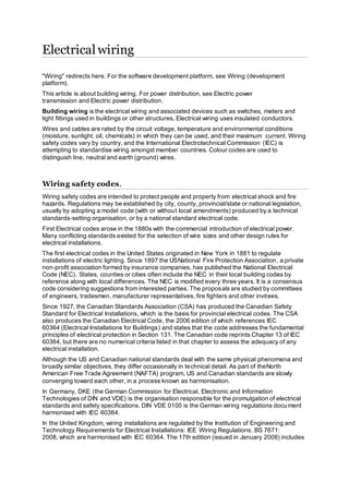
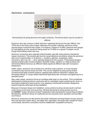
Metal-sheathed wires.
Lead cased electrical wire from a circa 1912 house in Southern England. Two conductors are sheathed in
red and black rubber, the central earth wire is bare. These wires are dangerous because the sheath is
prone to split if repeatedly flexed.](https://image.slidesharecdn.com/electricalwiring-161122062021/85/Electrical-wiring-7-320.jpg)
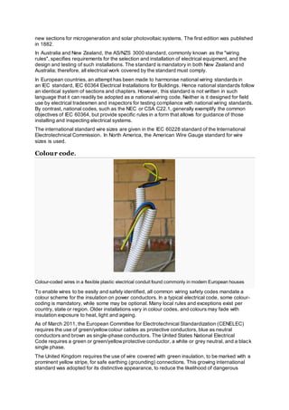
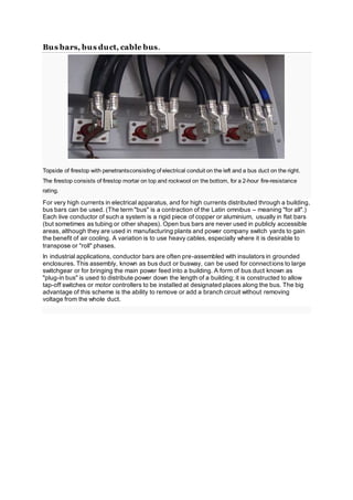
![In the United Kingdom, an early form of insulated cable, introduced in 1896, consisted of two
impregnated-paper-insulated conductors in an overall lead sheath. Joints were soldered, and
special fittings were used for lamp holders and switches. These cables were similar to
underground telegraph and telephone cables of the time. Paper-insulated cables proved
unsuitable for interior wiring installations because very careful workmanship was required on the
lead sheaths to ensure moisture did not affect the insulation.
Cables.
Wiring for extremely wet conditions
Armoured cables with two rubber-insulated conductors in a flexible metal sheath were used as
early as 1906, and were considered at the time a better method than open knob-and-tube wiring,
although much more expensive.
The first rubber-insulated cables for building wiring were introduced in 1922 with US patent
1458803, Burley, Harry & Rooney, Henry, "Insulated electric wire", issued 1923-06-12, assigned
to Boston Insulated Wire And Cable.[citation needed]
These were two or more solid copper electrical
wires with rubber insulation, plus woven cotton cloth over each conductor for protection of the
insulation, with an overall woven jacket, usually impregnated with tar as a protection from
moisture. Waxed paper was used as a filler and separator.
Over time, rubber-insulated cables become brittle because of exposure to atmospheric oxygen,
so they must be handled with care and are usually replaced during renovations. When switches,
socket outlets or light fixtures are replaced, the mere act of tightening connections may cause
hardened insulation to flake off the conductors. Rubber insulation further inside the cable often is
in better condition than the insulation exposed at connections, due to reduced exposure to
oxygen.
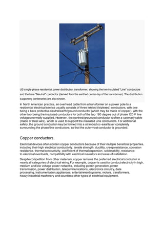
The sulphur in vulcanised rubber insulation attacked bare copper wire so the conductors were
tinned to prevent this. The conductors reverted to being bare when rubber ceased to be used.
Diagram of a simple electrical cable with three insulated conductors](https://image.slidesharecdn.com/electricalwiring-161122062021/85/Electrical-wiring-8-320.jpg)

This document provides information about building wiring and electrical codes. It discusses the types of wiring used in buildings, including rubber-insulated cables from the early 20th century and aluminum conductors. Wiring safety codes are intended to protect people from electrical shock and fire, and regulations vary by location. Color codes are also used to identify electrical wires.


