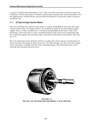
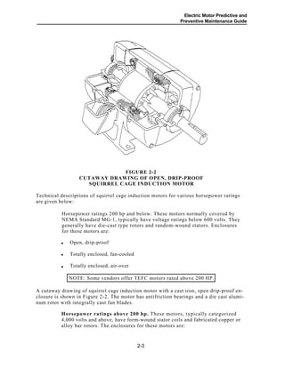
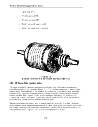
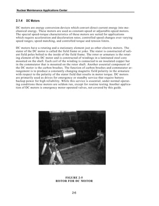
R E P O R T S U M M A R Y
Electric Motor Predictive and Preventive
Maintenance Guide
Electric motor failure could result in lost capacity as well as excessive
repair and maintenance costs. This guide provides information on
establishing an effective maintenance program to help prevent
unexpected motor failures, costly downtime, and unnecessary
maintenance costs. Specifically, the guide summarizes technical
data relative to four basic power plant motor types and associated
components.
BACKGROUND Maintenance recommendations proposed by electric motor
vendors have sometimes encouraged many overly conservative maintenance
practices. These practices have led to excessive maintenance activities and costs
that have not provided an extra margin of operability. Current work was prompted
by a need to determine appropriate maintenance techniques and tasks for specific
applications based on the type and size of electric motors and components.
INTEREST CATEGORIES
Nuclear plant operations
and maintenance
Plant electrical systems
and equipment
OBJECTIVE To provide utilities with guidance for establishing an effective motor
maintenance program, which should prevent unexpected failures through planned
motor maintenance efforts.
Engineering and technical
support
Industrial
APPROACH EPRI relied on supply and repair facility personnel as well as the
Nuclear Plant Reliability Data System to evaluate the operational history and fail-
ure modes of various motor types and sizes. They reviewed numerous electrical
test and inspection methods, determining how effectively each method revealed
the operating condition of electric motors. Then they compiled these methods and
matched them with appropriate motor types based on their use in performing
motor evaluations. The analysis evaluated motor components as well as the entire
motor unit to detect signals that could provide trending information.
KEYWORDS
Electric motors
Induction motors
Electrical equipment
Electrical testing
Maintenance
Bearings
RESULTS This guide summarizes technical data on the four basic types of
power plant motors and their components; it correlates failure causes, symptoms,
and modes. The guide further addresses the significant causes of motor failures
and outlines methods to optimize service life and minimize maintenance costs
through appropriate preventive maintenance programs. Test and maintenance
recommendations for different motor sizes and types are arranged to allow clear
comparison of motor reliability with function and cost effectiveness. Throughout
the guide, easy-to-read charts and tables chronicle the data.
On the basis of information provided in this guide, maintenance personnel in
nuclear and fossil plants can customize their programs for specific motors ac-
cording to service applications and operating conditions. To assist in this effort,
the guide includes a glossary of terms, regreasing guidelines for motors with
antifriction bearings, and oil-monitoring guidelines for electric motors with oil bath
bearings.
EPRI NP-7502s Electric Power Research Institute
EPRI PERSPECTIVE This guide provides a foundation for an effective
electric motor maintenance program with simple, but viable, testing rou-
tines that increase assurance of efficient motor operation. In all, the guide
simplifies selection of predictive and preventive maintenance tasks to
help maintenance personnel plan motor repairs during scheduled out-
ages and avoid costly unexpected failures. Related EPRI reports include
GS-7352, Manual of Bearing Failure and Repair; NP-3357, Condition
Monitoring of Nuclear Plant Electrical Equipment; and CS-5328, Signature
Analysis, Rotating Equipment Monitoring.
PROJECT
RP2814-35
Project Managers: Wayne E. Johnson; Vic Varma
Nuclear Maintenance Applications Center / Nuclear Power Division
For further information on EPRI research programs, call
EPRI Technical Information Specialists (415) 855-2411.
Contractor: Bechtel Group, Inc.
Electric Motor Predictive and Preventive Maintenance
Guide
NP-7502
Research Project 2814-35
Final Report, July 1992
Prepared by
BECHTEL GROUP, INC.
San Francisco, California 94119
Principal Investigator
J. A. Oliver
Prepared for
Nuclear Maintenance Applications Center
1300 Harris Boulevard
Charlotte, North Carolina 28262
Operated by
Electric Power Research Institute
3412 Hillview Avenue
Palo Alto, California 94304
EPRI Project Managers
W. E. Johnson
V. Varma
Nuclear Power Division
Effective December 6, 2006, this report has been made publicly available in accordance
with Section 734.3(b)(3) and published in accordance with Section 734.7 of the U.S. Export
Administration Regulations. As a result of this publication, this report is subject to only
copyright protection and does not require any license agreement from EPRI. This notice
supersedes the export control restrictions and any proprietary licensed material notices
embedded in the document prior to publication.
DISCLAIMER OF WARRANTIES AND
LIMITATION OF LIABILITIES
THIS REPORT WAS PREPARED BY THE ORGANIZATION(S) NAMED BELOW AS AN ACCOUNT OF WORK SPONSORED
OR COSPONSORED BY THE ELECTRIC POWER RESEARCH INSTITUTE, INC. (EPRI). NEITHER EPRI, ANY MEMBER
OF EPRI, ANY COSPONSOR, THE ORGANIZATION(S) NAMED BELOW, NOR ANY PERSON ACTING ON BEHALF OF ANY
OF THEM:
(A) MAKES ANY WARRANTY OR REPRESENTATION WHATSOEVER, EXPRESS OR IMPLIED, (I) WITH RESPECT TO
THE USE OF ANY INFORMATION, APPARATUS, METHOD PROCESS, OR SIMILAR ITEM DISCLOSED IN THIS REPORT,
INCLUDING MERCHANTABILITY AND FITNESS FOR A PARTICULAR PURPOSE, OR (II) THAT SUCH USE DOES NOT
INFRINGE ON OR INTERFERE WITH PRIVATELY OWNED RIGHTS INCLUDING ANY PARTY'S INTELLECTUAL PROPERTY,
OR (III) THAT THIS REPORT IS SUITABLE TO ANY PARTICULAR USER'S CIRCUMSTANCE; OR
(B) ASSUMES RESPONSIBILITY FOR ANY DAMAGES OR OTHER LIABILITY WHATSOEVER (INCLUDING ANY
CONSEQUENTIAL DAMAGES, EVEN IF EPRI OR ANY EPRI REPRESENTATIVE HAS BEEN ADVISED OF THE POSSIBILITY
OF SUCH DAMAGES) RESULTING FROM YOUR SELECTION OR USE OF THIS REPORT OR ANY INFORMATION,
APPARATUS, METHOD, PROCESS, OR SIMILAR ITEM DISCLOSED IN THIS REPORT.
ORGANIZATION(S) THAT PREPARED THIS REPORT:
BECHTEL GROUP, INC.
Price: $11,300.00
Electric Power Research Institute and EPRI are registered service marks of Electric Power Research Institute, Inc.
Copyright © 1992 Electric Power Research Institute. All rights reserved
ORDERING INFORMATION
Requests for copies of this report should be directed to the Nuclear Maintenance Applications
Center (NMAC), 1300 Harris Blvd., Charlotte, NC 28262, (800) 356-7448. There is no charge
for reports requested by EPRI member utilities and affiliates, U.S. utility associates, U.S.
Government agencies (federal, state, and local), media, and foreign organizations with which
EPRI has an information exchange agreement.
Electric Motor Predictive and
Preventive Maintenance Guide
ABSTRACT
Electric motor performance is vital to the reliable and efficient operation of power plants.
The failure of one or more critical motors could cause lost capacity and excessive repair
and maintenance cost. However, existing maintenance recommendations proposed by
vendors for electric motors have sometimes encouraged many overly conservative mainte-
nance practices. These practices have lead to excessive maintenance activities and costs
which have provided no extra margin of operability.
EPRI has sponsored RP2814-35 to develop a guide which provides power plants with in-
formation and guidance for establishing an effective maintenance program which will aid
in preventing unexpected motor failures and assist in planning motor maintenance ef-
forts. The guide includes a technical description which summarizes technical data rela-
tive to the four basic types of motors and their components in general use in power
plants. The significant causes of motor failures are investigated and described in detail
and methods to optimize service life and minimize maintenance cost through appropriate
preventive maintenance and conditioning program are presented.
This guide provides a foundation for an effective electric motor maintenance program
and simplifies the selection of predictive and preventive maintenance tasks. Its use will
enable maintenance personnel in nuclear and fossil plants to plan motor repairs during
scheduled outages and avoid costly unexpected failures.
iii
Electric Motor Predictive and
Preventive Maintenance Guide
ACKNOWLEDGMENTS
NMAC Electric Motor Predictive and Preventive Maintenance Guide was developed
with the help of many organizations and individuals. Mr.Gary D. Matthews of Illinois
Power Company arranged for major financial and technical support for this project.
Reda Helmy and Emery Fabri of Bechtel contributed to the early draft of the text. We
also wish to recognize the following individuals who freely contributed their time and
knowledge in molding this Guide in its present form.
Illinois Power CompanyKevin E. Moore
Tennessee Valley AuthorityJerry S. Honeycutt
Illinois Power CompanyWilliam D. Nelson
Detailed review and comments by the following have helped enormously in enhancing
the quality of this document.
Alabama Power CompanyTom Higgins
Arizona Public ServiceRobert Whiting
Baltimore Gas and Electric Co.
Commonwealth Edison Company
Houston Electric Light and Power
Oglethorpe Power Corporation
Rochester Gas and Electric
Union Electric Company
EPRI
Bill Nowicki
Jim Andrasco
Steve Hill
Rudy Castorina
John Sargent
Gary J. Czeschin
Jan Stein
v
Electric Motor Predictive and
Preventive Maintenance Guide
vii
CONTENTS
Section Page
1.0 Introduction 1-1
1.1 Scope and Purpose of Guide .............................................................. 1-1
1.2 Organization of Guide.......................................................................... 1-2
2.0 Technical Description 2-1
2.1 Electrical Motors................................................................................... 2-1
2.1.1 AC Squirrel Cage Induction Motors ............................................. 2-2
2.1.2 AC Wound-Rotor Induction Motors.............................................. 2-4
2.1.3 AC Synchronous Type Motors..................................................... 2-5
2.1.4 DC Motors.................................................................................... 2-6
2.1.5 Construction Features and Application........................................ 2-7
2.2 Motor Components............................................................................... 2-8
2.2.1 Motor Components Overview ...................................................... 2-8
2.2.2 Bearing Systems........................................................................ 2-15
2.2.3 Lubrication Systems .................................................................. 2-21
3.0 Component Failure Mode Analysis 3-1
3.1 Industry Surveys................................................................................... 3-1
3.2 Failure Mode Analysis.......................................................................... 3-3
3.2.1 Cause of Failure .......................................................................... 3-3
3.2.2 Summary of Failure Causes ........................................................ 3-6
Nuclear Maintenance Applications Center
viii
Section Page
4.0 Preventive/Predictive Techniques 4-1
4.1 Trendable Tests.................................................................................... 4-1
4.2 Inspection Techniques......................................................................... 4-6
4.3 Other Diagnostic................................................................................... 4-7
4.4 Summary Of Tests and Inspections.................................................... 4-9
5.0 Recommendations 5-1
5.1 Overview................................................................................................ 5-1
5.2 Recommended Tests/Inspections and
Associated Performance...................................................................... 5-2
Frequencies .......................................................................................... 5-2
5.2.1 Trendable .................................................................................... 5-2
5.2.2 Non-Trendable............................................................................. 5-4
5.2.3 Summaries of Recommended Tests............................................ 5-5
5.3 Non-periodic Tests/Inspections.......................................................... 5-5
6.0 References 6-1
Appendices
Glossary .....................................................................................................A-1
Regreasing Guidelines ...................................................................................B-1
Oil Monitoring..................................................................................................C-1
Index I-1
Electric Motor Predictive and
Preventive Maintenance Guide
ix
FIGURES
Figure Page
2-1 Detail of Rotor for Squirrel Cage Motor................................................................. 2-2
2-2 Cutaway Drawing of Open, Drip-Proof Squirrel Cage
Induction Motor ..................................................................................................... 2-3
2-3 Rotor For Wound-Rotor Induction Motor............................................................... 2-4
2-4 Rotor For Synchronous Motor............................................................................... 2-5
2-5 Rotor For DC Motor .............................................................................................. 2-6
2-6 Exploded View of AC Motor.................................................................................. 2-10
2-7 Wound-Rotor Induction Motor............................................................................... 2-12
2-8 Synchronous Motor Details................................................................................... 2-14
2-9 Exploded View of DC Motor.................................................................................. 2-16
2-10 Sleeve Bearing Details ......................................................................................... 2-20
2-11 Oil Ring Details ..................................................................................................... 2-20
2-21A Single Row, Double Sealed Ball Bearing.............................................................. 2-24
2-12B Single Row, Maximum Type Ball Bearing ............................................................. 2-24
2-12C Single Row, Open Enclosure, Deep Groove Ball Bearing .................................... 2-24
2-21D Single Row, Double Shielded Ball Bearing ........................................................... 2-24
2-21E Mounting Arrangements For Angular-Contact Ball Bearings ................................ 2-25
2-13A Tilting-Pad Journal Bearing................................................................................... 2-26
2-13B Equalized Support of Thrust Bearing Shoes......................................................... 2-26
2-13C Assembly of Six-Shoe Thrust Bearing .................................................................. 2-26
2-13D Vertical Runner Added to Six-Shoe Thrust Bearing.............................................. 2-26
2-14 Flow-Through Lubrication System ........................................................................ 2-27
2-15 Lubrication System Used for Shielded bearings ................................................... 2-27
Nuclear Maintenance Applications Center
x
Figure Page
B-1 Grease Amount Curve .......................................................................................... B-6
C-1 Failure Modes Associated with Size and Concentration
of Particles............................................................................................................ C-3
C-2 Tests Used to Detect particles.............................................................................. C-4
Electric Motor Predictive and
Preventive Maintenance Guide
xi
TABLES
Table Page
2-1 Construction Features.......................................................................................... 2-7
2-2 Common Application Chart .................................................................................. 2-7
2-3 Predominant Motor Components Summary ......................................................... 2-17
2-4 Bearing Application .............................................................................................. 2-19
3-1 percent of Failures by Major Components............................................................ 3-1
3-2 Motor Failures by Significant Causes................................................................... 3-2
3-3 Causes, Symptoms, and Failure Modes of Electric Motors .................................. 3-7
4-1 Trendable Tests ................................................................................................... 4-5
4-2 Other Tests .......................................................................................................... 4-9
4-3 Applicable Test/Inspections for Observed Symptoms .......................................... 4-11
5-1 Recommended Tests: Squirrel Cage Induction Motors
Under 200 HP, Random Wounded Stator, Less Than 600 Volts,
Antifriction Bearings, Safety Related and Balance of Plant ................................. 5-7
5-2 Recommended Tests: Squirrel Cage Induction Motors
Above 200 HP, Form Wound Stator, 4000 Volts and Higher,
Antifriction Bearings, Safety Related and Balance of Plant ................................. 5-8
5-3 Recommended Tests: Wound Rotor Induction Motors
Under 200 HP and Above, Form Wound Stator, 4000 Volts
and Higher, Sleeve, Pad or Disc Bearings, Safety Related
and Balance of Plant............................................................................................ 5-9
5-4 Recommended Tests: Wounded Rotor Induction Motors
Under 200 HP, Random Wound Stator, Less than 600 Volts
Antifriction Bearings, Safety Related and Balance of Plant ................................. 5-10
5-5 Recommended Tests: Synchronous Motors 1000 HP and
Above, From Wound Stator, 4000 Volts and Higher, Sleeve,
Pad or Disc Bearings, Balance of Plant ............................................................... 5-11
5-6 Recommended Tests: DC Motor Under 100 HP, 115 Volts
or 230 Volts, Antifriction Bearings, Safety Related and
Balance of Plant................................................................................................... 5-12
Nuclear Maintenance Applications Center
xii
Table Page
B-1 Regreasing Intervals............................................................................................. B-4
C-1 Oil Analysis Tests ................................................................................................. C-5
C-2 Test Period ........................................................................................................... C-6
Electric Motor Predictive and
Preventive Maintenance Guide
Section 1.0
Introduction
Electric Motor Predictive and
Preventive Maintenance Guide
Introduction1.0
Scope and Purpose of Guide1.1
A nuclear power plant utilizes large numbers of electric motors ranging in size from frac-
tional horsepower to many thousands of horsepower. Unanticipated failure of motors in
critical service may result in equipment damage and affect plant availability. Motor fail-
ures can be substantially reduced by applying proper predictive and preventive mainte-
nance techniques.
The purpose of the guide is to provide nuclear power plant licensees with information
and guidance for establishing an effective maintenance program for primary system and
balance of plant electric motors.
The guide outlines the most probable failure modes and provides information on the
available methods to optimize service life and minimize maintenance cost through effec-
tive preventive maintenance and condition monitoring. The guide concentrates on estab-
lishing the maintenance program. It briefly describes effective tests and identifies the
effectiveness of each test. Trending of tests is discussed. References are provided for
further detailed technical information on tests and test procedures. Test and mainte-
nance recommendations for different types and sizes of motors have been designed to en-
sure motor reliability commensurate with functions and cost effectiveness.
Data is laid out in easy to read tables and charts. Based on the information available in
this guide, personnel responsible for maintenance can customize their maintenance pro-
gram for specific motors according to service application and operating conditions.
While the recommendations in this guide are applicable to all motors in general, 10 CFR
50.49 (Reference 6.20) motors in a nuclear power plant may have additional mainte-
nance and testing requirements. These plant-specific requirements are not covered in
this guide. In addition, electric motors for motor-operated valves are not included due to
the limited amount of maintenance performed on these types of motors.
Recommendations in this guide have been developed using Reliability Centered Mainte-
nance (RCM) techniques. Data sources included:
Discussions with power plant maintenance personnel•
Discussions with motor repair shop personnel
Motor manufacturers' experience
Discussions with diagnostic test equipment manufacturers
IEEE, NUREG, and other technical publications
Nuclear Plant Reliability Data System and other industry databases
A complete listing of reference source material is provided in Section 6.
1-1
•
•
•
•
•
Nuclear Maintenance Applications Center
1.2 Organization of Guide
This guide is organized in six sections and three appendices as follows:
Section 1, Introduces and summarizes the scope and purpose of the guide and
describes its organization.
•
Section 2, Technical Description, summarizes technical data relative to the four
basic types of motors and their components in general use in power plants.
Section 3, Component Failure Analysis, covers the significant causes of motor
failures and the observable conditions associated with these failures.
Section 4, Preventive/Predictive Techniques, details technical factors to be con-
sidered when preparing a preventive maintenance plan and maintenance
trends to be used to establish predictive maintenance.
Section 5, Recommendations, describes the recommended predictive tests and
preventive maintenance tasks for power plant motors and discusses how to
apply these various techniques.
Section 6, References, presents a list of related materials used either in the de-
velopment of this guide or referenced for further detailed information.
Appendix A is a glossary of terms used in this guide.
Appendix B presents regreasing guidelines for motors with antifriction bearings.
Appendix C presents oil monitoring guidelines for electric motors with oil bath
bearings.
1-2
•
•
•
•
•
•
•
•
Electric Motor Predictive and
Preventive Maintenance Guide
Section 2.0
Technical Description
Electric Motor Predictive and
Preventive Maintenance Guide
Technical Description2.0
This section includes technical descriptions of the types of motors used in power plants
and the components important for consideration in maintenance programs.
Section 2.1, Motors
Section 2.2, Motor Components
The purpose of these sections is to give an overview of the different types of motors gen-
erally used in nuclear power plants. For detailed description, refer to EPRI Publication
EL-5036, Volume 6: Motors (Reference 6.1)1. Appendix A, Glossary of Terms, provides
additional definitions of motor types and related components.
Electric Motors2.1
The principle function of an electric motor is to convert electric energy into mechanical
energy. The conversion is accomplished by two main component- the stator and rotor.
Regardless of the type and application of an electric motor, all motors will be made up of
these two main components. The stator is the stationary component and the rotor is the
rotating component. These components are separated by a small air-gap clearance to
avoid mechanical rubbing.
The stator is generally made up of a winding, the frame, and the laminated steel punch-
ings (core iron). The stator coils can be random wound (loops of wire) or form wound
(pre-formed diamond shape) coils of magnet wire.
The rotor is usually made up of laminated steel punchings (core iron), coils or rotor bars,
shorting rings and a shaft.
Electric motors can be broken into three main categories: induction, synchronous, and
DC. Each of these categories can be further sub-divided as follows:
Induction Motors: Squirrel-cage, Wound rotor
Synchronous Motors: Cylindrical rotor or Salient pole
DC Motors: Shunt wound, Series wound, or Compound wound
The following descriptions do not list all the available combinations of motor types but
highlight only major types used in the power industry. Most of the motors used in
power plants are of the squirrel cage induction type. Squirrel cage induction motors em-
ploy the simplest and most rugged construction. They are generally the most economical
1
Much of the book covers induction motors. Section 6.12, page 6-158 relates to synchronous motors and
Section 6.13, page 6-160 discusses DC motors.
2-1
•
•
Nuclear Maintenance Applications Center
in terms of initial and maintenance costs. They also have a proven record for long term
reliability. Of the many types of motors used in power plants, this section describes vari-
ous applications, classifications, and construction features of four basic types of motors
in general use.
2.1 .1 AC Squirrel Cage Induction Motors
The rotor winding of a squirrel-cage motor is usually embedded in slots near the outer
surface of the rotor. For larger motors, the winding is made up of uninsulated copper,
copper alloy, or other suitable bar or rod material embedded in the slots of the rotor
punchings. The rotor bars or rods extend beyond the ends of the rotor punchings and
are connected together by shorting rings to provide closed-loop current paths. (See Fig-
ure 2-1).
Die cast aluminum rotors perform similar to copper bar rotors and are used because of
their economic advantage in fabrication cost. In either design, it is the rotor bar conduc-
tivity and shape, coupled with the stator winding design, that determines the motor
starting and running characteristics.
FIGURE 2-1
DETAIL OF ROTOR FOR SQUIRREL CAGE MOTOR
2-2
Electric Motor Predictive and
Preventive Maintenance Guide
FIGURE 2-2
CUTAWAY DRAWING OF OPEN, DRIP-PROOF
SQUIRREL CAGE INDUCTION MOTOR
Technical descriptions of squirrel cage induction motors for various horsepower ratings
are given below:
Horsepower ratings 200 hp and below. These motors normally covered by
NEMA Standard MG-1, typically have voltage ratings below 600 volts. They
generally have die-cast type rotors and random-wound stators. Enclosures
for these motors are:
.
Open, drip-proof
Totally enclosed, fan-cooled
Totally enclosed, air-over
NOTE: Some vendors offer TEFC motors rated above 200 HP.
A cutaway drawing of squirrel cage induction motor with a cast iron, open drip-proof en-
closure is shown in Figure 2-2. The motor has antifriction bearings and a die cast alumi-
num rotor with integrally cast fan blades.
Horsepower ratings above 200 hp. These motors, typically categorized
4,000 volts and above, have form-wound stator coils and fabricated copper or
alloy bar rotors. The enclosures for these motors are:
.
2-3
•
•
•
Nuclear Maintenance Applications Center
Open, drip-proof
Weather protected I
Weather protected II
Totally enclosed, water-cooled
Totally enclosed, pipe ventilated
FIGURE 2-3
ROTOR FOR WOUND-ROTOR INDUCTION MOTOR
2.1.2 AC Wound-Rotor Induction Motors
The rotor winding of a wound-rotor motor consists of coils of insulated magnet wire
placed in the slots of the rotor (see Figure 2-3). The coils are connected in a three phase
arrangement. The lead ends of the winding are connected to insulated, rotor-mounted
collector rings. A rotor-current path to an external rotor circuit is completed through
carbon brushes. The external circuit usually contains resistance. By adjusting the
value of the external resistance, certain operational characteristics of the motor can be
controlled (i.e. torque, current, and speed) within limits.
Wound-rotor induction motors used in power plants are generally less than 200 horse-
power and 600 volts. These motors are used in a few applications that require speed con-
trol or special torque considerations. The stator of a wound-rotor induction motor is the
same as the stator of a squirrel cage induction or synchronous motor.
2-4
•
•
•
•
•
Electric Motor Predictive and
Preventive Maintenance Guide
2.1.3 AC Synchronous Type Motors
The stator of a synchronous motor is the same as that of an induction motor. The rotor
of a synchronous motor differs in that it has two windings. One winding, called a
damper winding, is similar in construction to a squirrel-caged motor. It is utilized dur-
ing starting to create asynchronous torque. It is also used to damp out oscillations re-
sulting from load fluctuations during normal operations. The second winding, called a
field winding, provides excitation, using an external DC source. It produces a magnetic
field on the rotor to facilitate synchronous operation. The field winding is usually formed
of magnet wire shaped to fit around salient-poles (see Figure 2-4). The synchronous mo-
tor with brushless excitation system (see Figures 2-4) has an exciter mounted on the
shaft. The design of the rotor is such that alternate north and south poles complete the
magnetic circuits of the motor. The rotor has the same number of poles as the stator.
The magnetic field of the rotor locks in step with opposite-polarity of the rotating mag-
netic field of the stator and thus, the rotor revolves at the same (synchronous) speed de-
termined by the number of poles in the stator and rotor. Synchronous motors are often
used for large, low speed circulating water pumps and aid in auxiliary system power fac-
tor correction. These motors are often vertically mounted and have voltage ratings
above 4,000 volts.
FIGURE 2-4
ROTOR FOR SYNCHRONOUS MOTOR
2-5
Nuclear Maintenance Applications Center
2.1.4 DC Motors
DC motors are energy conversion devices which convert direct current energy into me-
chanical energy. These motors are used as constant-speed or adjustable-speed motors.
The special speed-torque characteristics of these motors are suited for applications
which require acceleration and deceleration rates; controlled speed changes over varying
speed ranges; speed matching, and controlled torque and tension limits.
DC motors have a rotating and a stationary element just as other electric motors. The
stator of the DC motor is called the field frame or yoke. The stator is constructed of sali-
ent field poles bolted to the inside of the field frame. The rotor or armature is the rotat-
ing element of the DC motor and is constructed of windings in a laminated steel core
mounted on the shaft. Each coil of the winding is connected to an insulated copper bar
in the commutator that is mounted on the rotor shaft. Another essential component of
the DC motor is the carbon brushes. The function of carbon brushes and commutator ar-
rangement is to produce a constantly changing magnetic field polarity in the armature
with respect to the polarity of the stator field that results in motor torque. DC motors
are primarily used as drives for emergency or standby service that require battery
backup power for high reliability. While this service is essential, under normal operat-
ing conditions these motors are seldom run, except for routine testing Another applica-
tion of DC motors is emergency motor operated valves, not covered by this guide.
FIGURE 2-5
ROTOR FOR DC MOTOR
2-6
Electric Motor Predictive and
Preventive Maintenance Guide
2.1.5 Construction Features and Application
Tables 2-1 and 2-2 identify the construction features of the different types of motors and
their usual application in a power plant.
TABLE 2-1
CONSTRUCTION FEATURES
Features Squirrel Cage Synchronous Wound Rotor DC Motors
Slip Rings X X
3-Phase Stator
X X X
Salient Pole
Stator X
Die-Cast Rotor
X
Fabricated Rotor
Bars X X
Salient Pole Rotor X
3-Phase Rotor
X
Commutator X
Excitation System X X
TABLE 2-2
COMMON APPLICATION CHART
Motor Types
DC MotorsWound RotorApplication SynchronousSquirrel
Cage
Most Pumps and Fans X
Circulating Water Pumps X X
Cranes and Hoists
X X
Emergency DC Service X
Compressors X X X
2-7
Nuclear Maintenance Applications Center
2.2 Motor Components
There are three essential components that make the operation of the electric motor possi-
ble. The windings, which receive current from an electrical supply system, the active
iron (stator and rotor cores) which provides a path for magnetic flux, and the stator hous-
ing with structural support elements, make up the electric motor.
The motor components of concern for motor maintenance programs are discussed in this
section:
Section 2.2.1 summarizes the features of the motor components by motor type.
Section 2.2.2 discusses bearing systems and applications.
Section 2.2.3 summarizes lubricants and lubrication systems.
2.2.1 Motor Components Overview
The stator housing protects and supports the stator core and windings. The support
structure for most electric motors consists of two endbells (bearing housings), and a sta-
tor frame. The stator frame and endbells are often made of cast iron, fabricated steel or
in some instances cast aluminum. With horizontal motors, the stator housing with
mounting feet usually doubles as the mounting system for the motor. Vertical motors
are usually anchored or supported by a lower mounting flange on the bottom endbell.
Rotor shafts are usually carbon or special steel alloy.
The stator frame houses the stator core which is made of stacked insulated laminated
punchings, with slots which allow for winding placement. The stator frame also pro-
vides support for brackets and rings for the endturns of the windings. The endbells con-
tain the bearings which allow for correct positioning of the rotor with the respect to the
stator. Correct positioning of the rotor will maintain a sufficient and uniform air gap be-
tween stator and rotor. Often enclosures of large motors contain air baffles which aid in
the ventilation of the core, windings and bearings.
The stator windings receive the applied voltage and are so arranged to produce a rotat-
ing magnetic field within the confines of the stator. These windings are made of magnet
wire which is formed to make coils. The magnet wire is coated with an insulating mate-
rial which provides the turn-to-turn and phase separation. The coils are further insu-
lated by layers of insulating material which provide electrical isolation from the stator
core iron. The coil ends are brought out, connected and insulated to form the required
series or parallel circuits.
Both stator and rotor cores are made of low loss insulated laminations that are stacked,
aligned and clamped. Thin laminations are used to reduce hysteresis and eddy current
losses to minimize core heating. When the motor is fully assembled, the rotor core is in-
side the stator core and the two are separated by an air gap. Magnetic flux passes
across the air gap to complete the magnetic circuit. The magnetic flux reacting with the
induced current in the rotor conductors produces torque, causing the rotor to rotate.
2-8
•
•
•
Electric Motor Predictive and
Preventive Maintenance Guide
AC MOTORS - Nema Type, Squirrel Cage Induction Motors, Up To 200 Horsepower,
600 Volts And Lower (References 6.22 and 6.33). Design features include:
Stator
Winding: Three-phase winding consisting of various insulating materials.
Conductors are made from insulated magnet wire.
-
Core: Stacked laminations, insulated with iron oxide, enamel, aluminum
phosphate, or other insulating material.
-
Rotor
Winding: Die-cast or fabricated
Shorting Rings: Die-cast or fabricated
Core: Similar to stator core material
-
-
-
Shaft: Carbon steel or special steel alloy-
Bearings: Antifriction (ball or roller) or, occasionally, sleeve bearings.
Frame: Cast iron, die-cast aluminum or sheet steel
Fan: Molded plastic, sheet metal or cast metal alloy
Figure 2-6 shows an exploded view of a NEMA type squirrel cage induction motor with
random-wound stator, die cast aluminum rotor and antifriction bearings. This is a to-
tally-enclosed, fan-cooled motor. The external fan and fan cover are shown.
2
Pages 2-1, 2-2, and 2-3 show details of small motors.
3
Pages 2-1 through 4-1 show details of small motors including winding arrangements.
2-9
•
•
•
•
•
Nuclear Maintenance Applications Center
FIGURE 2-6
EXPLODED VIEW OF AC MOTOR -
2-10
Electric Motor Predictive and
Preventive Maintenance Guide
AC MOTORS - Above 200 Horsepower, 4000 Volts And Higher. Design features in-
clude:
Stator
Winding: Three-phase winding consisting of insulated formed coils.
Several resin treatments exist for these systems (vacuum-pressure
impregnation, resin-rich, etc.).
- Core: Laminated electrical grade steel sheets, insulated
-
Rotor
Winding. Rotor bars of fabricated conductors made of copper, alloy,
or aluminum
-
Core: Same as stator core.-
Shaft: Carbon steel or special steel alloy-
Bearings: In some cases, antifriction bearings are used in motors up to 2000
hp. Ring lubricated sleeve bearings are used for most horizontal motors. Ver-
tical motors often use plate or pivoting shoe type thrust bearings.
Oil-lubricated bearings may have cooling coils in the oil reservoir. Water is circu-
lated through cooling coils to reduce oil temperature.
Frame: Usually fabricated from carbon-steel plates or cast iron.
Wound-Rotor Induction Motors. Stator winding, stator core, rotor core, shaft, and
bearings are similar to squirrel cage induction motor components. Other design fea-
tures include:
Rotor Winding: Insulated conductors formed into a 3-phase winding
Slip Rings: Steel, brass or bronze rings connected to a 3-phase winding
Carbon Brushes and Brush Rigging: Carbon brushes fitted with flexible
copper wire cables called pigtails are mounted in brush holders with springs
and some have tension adjusting devices. Carbon brushes ride on slip ring
surfaces to conduct rotor current to the controller.
Figure 2-7 shows a cutaway drawing of a NEMA size wound rotor induction motor. This
is an open, drip-proof motor with internal fans, slip rings and antifriction bearings.
2-11
•
•
•
•
•
•
•
Nuclear Maintenance Applications Center
FIGURE 2-7
WOUND-ROTOR INDUCTION MOTOR
2-12
-
-
-
-
Electric Motor Predictive and
Preventive Maintenance Guide
AC MOTORS - SYNCHRONOUS TYPE. Stator components are the same as for AC
induction motors 1000 hp and above. Other design features include:
Rotor
Winding: The synchronous motor has an insulated rotor winding consisting
of copper conductors in a concentrated salient pole field coil. It also has a
damper winding that is used for starting the motor.
Core: The synchronous motor has salient poles that are attached to a central
rim by bolts or dovetail connections.
Shaft: Carbon steel or special steel alloy
Slip Rings: Steel or bronze slip rings are mounted on and insulated from the
rotor shaft, with electrical connections to the insulated field windings.
Rotating, Brushless Exciter: Instead of slip rings, the motor may have
mounted on its shaft, a rotating alternator with rectifier diodes to supply the
insulated field winding with field current.
Carbon Brushes: Where slip rings are furnished, carbon brushes, and brush
holders are used to supply the insulated field winding with field current.
Bearings: Bearings for these high horsepower, low rpm, vertical type motors
are oil-lubricated, usually of the sleeve type for guide bearings and disc or
pad type for thrust bearings.
Frame: Usually fabricated from carbon steel plate.
Figure 2-4 shows a horizontal synchronous motor rotor with laminated rotor pole pieces,
damper winding with shorting rings, journals for sleeve bearings and brushless exciter.
Figure 2-8 shows a horizontal synchronous motor with solid steel pole pieces, bolted-on
pole caps, ring-lubricated sleeve bearings, brushless exciter and totally-enclosed, water-
cooled (TEWC) construction.
DC MOTORS. DC motors in power plants are usually rated below 100 horsepower. De-
sign features include:
Stator
Winding Windings on the stationary part of the motor are referred to as-
field windings. They are made of magnet wire and are insulated from the
field poles with insulating material.
Core and Poles: Can be either solid steel or laminated steel.-
2-13
•
•
•
•
•
•
Nuclear Maintenance Applications Center
FIGURE 2-8
SYNCHRONOUS MOTOR DETAILS
2-14
Electric Motor Predictive and
Preventive Maintenance Guide
Rotor
Winding: Windings on the rotating portion of the motor are referred to as a-
mature windings. They are made of insulated magnet wire.
-
Core: Stacked laminations, insulated with iron oxide, enamel aluminum
phosphate or other insulating material.
-
Shaft: Carbon steel or special steel alloy
Commutator: Insulated wedge shaped copper conducting elements formed
into a cylinder. Copper segments are insulated from the shaft and from each
other, and are connected to armature conductors.
Carbon Brushes and Brush Rigging: Carbon brushes supported by brush
rigging transfer current to the rotating commutator
Shaft: Carbon steel or special alloy steel
Bearings: Antifriction bearings
Figure 2-8 shows an exploded view of a DC motor of less than 100 hp rating. This is an
open, drip-proof motor with internal cooling fan and antifriction bearings. The rotating
armature has a commutator. The field poles are in the stationary stator frame.
2.2.2 Bearing Systems
Bearings are a crucial element in the reliable operation of an electric motor. Bearings
fall into three major categories: sleeve (see Figure 2-10), antifriction (see Figure 2-12A-
D), and thrust bearings which can be either antifriction bearings or plate type bearings
(see Figures 2-12E and 2-13). The type of bearings used in a motor depends on the serv-
ice requirements of the motor. Small motors typically use antifriction bearings. Large
motors often use babbit bearings; however, motors up to 2000 HP have been designed
with antifriction bearings. In addition, large vertical motors incorporate a thrust bear-
ing in their design. However there are exceptions to these generalities and it is impor-
tant for maintenance personnel to recognize bearing types and their orientation
(Reference 6.19).
2-15
•
•
•
•
•
Nuclear Maintenance Applications Center
FIGURE 2-9
EXPLODED VIEW OF DC MOTOR
2-16
Electric Motor Predictive and
Preventive Maintenance Guide
Predominant motor components by motor type are summarized in Table 2-3.
TABLE 2-3
PREDOMINANT MOTOR COMPONENTS SUMMARY
Squirrel cage induction motor
Wound rotor induction motor
Synchronous motor
Direct current motor
SCIM(a)
WRIM
SYNCH
DC
Bearings are the major cause of failure for electric motors (see Section 3). All motor
bearings are intended to have some form of lubrication. Bearing life is dependent on cor-
rect and adequate lubrication. Choice of lubricants depends on the following factors:
Type and size of bearing
Operating temperature
Bearing load
Bearing fit to shad and end-bell
Motor speed
Environment (humid, hot, dirty, high radiation, etc.)
Motor operating mode (continuous or standby)
2-17
•
•
•
•
•
•
•
=
=
=
=
Nuclear Maintenance Applications Center
Under continuous operation and normal load conditions, most antifriction bearings have
an average life expectancy of 5 to 10 years (Reference 6.14) whereas sleeve and thrust
bearings are considered to have indefinite life, if properly maintained. However, the fac-
tors listed above can have significant effect on bearing life expectancy. Over-lubrication
can be as detrimental to the bearings as under-lubrication. Forcing too much grease or
adding too much oil into a bearing reservoir will lead to overheating of the bearing and
may lead to incursion of the lubricant into the motor, resulting in damage to the wind-
ings. Therefore, it is important that correct type, amount, and frequency of lubrication
be determined for each motor.
Large motors use oil-lubricated bearings as bearing size and speed exceed the limits for
grease. These bearings can be either antifriction or babbitted bearings. Many of the
identified bearing failures relate to grease lubricated bearings.
Bearing types and applications are discussed below. Bearing types are related to bear-
ing application considerations rather than to motor types.
BEARING TYPES. The two principal types of self-lubricated bearings used are anti-
friction (rolling element bearings) and babbitted bearings. Most horizontal motors in
the 1 to 500 hp size range, and some motors up to 2000 hp. use antifriction bearings.
This type of bearing is lubricated by an oil reservoir or grease which acts as an oil reser-
voir, gradually releasing oil to the bearing surfaces. Larger horizontal motors usually
have oil-film babbitted sleeve bearings (see Figure 2-10). These bearings have an oil res-
ervoir from which oil is drawn by oil rings (see Figure 2-11), which rotate on the shaft
and dip into the oil reservoir. The rings deposit oil on the shaft and the bearing sur-
faces. Some large motors have force-fed lubrication supplied from a separate shaft-
driven or motor-driven pump.
The bearing types for horizontal and vertical motors are discussed in more detail below:
Antifriction Bearings. The basic difference in antifriction bearings is the
type of rolling element used in the bearing. The following types of rollers are
in wide use today: balls, cylindrical rollers, spherical rollers and tapered roll-
ers. Small direct-coupled horizontal motors use ball bearings. Horizontal mo-
tors using antifriction bearings that drive their loads with V-belts use ball
and roller bearings. Roller bearings are capable of higher side thrust loading
than ball bearings and sleeve bearings.
Sleeve Bearings. The sleeve bearing for horizontal motors is normally a simple
babbitt-lined steel cylinder. Oil rings, usually made of bronze or brass, ride on and
rotate with the shaft to carry oil up from a sump beneath the bearing, letting it flow
down onto the journal to spread oil between journal and bearing surfaces. Sleeve
bearings are in wide use on the larger motors in power plants. Sleeve bearings
should be avoided in belt drive applications.
4
Bearings and lubrication are extensively discussed in Section 6.9, pages 6-103 through 6-123.
2-18
•
•
Electric Motor Predictive and
Preventive Maintenance Guide
Since there are no statistical, standardized relations between load and life, sleeve
bearings unlike the antifriction type, are often expected to last indefinitely.
Experience has shown, however, that degradation of lubrication systems, vi-
bration and poor shaft alignment can lead to sleeve bearing wear and even-
tual failure.
Thrust Bearings. Thrust bearings of most vertical motors having large diame-
ters and rotor weight, such as circulating water pump motors, use oil-lubri-
cated disc or tilting pad bearings that have babbitted surfaces. Vertical
motors rated up to 2000 hp may use antifriction bearings as thrust bearings
in single, double, or triple arrangements depending on thrust loading.
Bearing Application. Table 2-4 shows how bearings are usually applied by horsepower.
TABLE 2-4
2-19
•
BEARING APPLICATION
Nuclear Maintenance Applications Center
FIGURE 2-10
SLEEVE BEARING DETAILS
FIGURE 2-11
OIL RING DETAIL
2-20
Electric Motor Predictive and
Preventive Maintenance Guide
Ball bearings are provided in a variety of configurations for requirements of load, speed,
thrust and lubrication design.
Sealed bearings prevent foreign material entry into the bearing. These bearings
are not usually designed to be relubricated. The bearing has a prebilled
grease level in its enclosed reservoir. (Figure 2-12A)
Single row, deep-groove, double-shielded bearings combine the bore and outside
diameter of single row bearings with the width of double row bearings for
wider area in contact with shaft and housing. This style is often used with
aluminum housings. Extra width provides extra grease capacity. Deep-
groove ball bearings tolerate moderate thrust loads. (Figure 2-12C,D)
Single row maximum type bearings are designed for heavy radial loads at mod-
erate speeds. A filling slot is milled into the inner and outer rings of the bear-
ing. They are used with or without shields, depending on the application.
Because of the filling slot these bearings have little thrust capability. (Figure
2-12B)
Angular contact ball bearings carry a combination of radial and single direction
thrust loads. To carry thrust loads in both directions, these bearings are
mounted in pairs with opposed contact angles. (Figure 2-12E)
Ball bearings for axial thrust loads can handle relatively high thrust loads
where no radial loads are present.
Bearings with pivoted shoes, also called tilting pads, are used in both horizontal shaft
and vertical shaft applications. Figure 2-13A shows a runner for tilting pad bearing.
Figures 2-13C and 2-13D show a six-shoe tilting pad thrust bearing with and without
the runner. The all steel runner is fixed to the rotating shaft and it rides on the six
shoes with babbitted surfaces. The pads tilt to allow an oil wedge to form on its surface
that supports the weight of the shaft assembly via the runner. Figure 2-13B shows sche-
matically how the individual thrust bearing shoes provide an equalized support system.
Lubrication Systems2.2.3
All motors have lubrication systems for bearings. Bearing life is primarily limited by
the adequacy of the lubricant. The type and quality of the lubricant are dependent upon
bearing type size, operating temperature, load, and motor speed. Bearings may be self-
lubricated or force-feed lubricated.
OIL LUBRICATION. Oil lubricated bearings are either submerged in an oil bath for
vertical motor applications or use a slinger or oil rings to coat the bearing with oil. Oil
viscosity selection is based on bearing loading. Vertical motors with antifriction thrust
bearings use fairly low viscosity oil. A heavily loaded spherical roller thrust bearing will
use higher viscosity oil. High operating temperatures will promote oil deterioration.
Some motors use cooling coils to limit bearing operating temperatures and retard oil dew
radation. Oil analysis should be used to periodically monitor the lubricant for degrada-
tion of physical properties and/or the presence of bearing wear. Equipment
manufacturers should be consulted when determining the correct oil (i.e., viscosity, addi-
2-21
•
•
•
•
•
-
Nuclear Maintenance Applications Center
tives, etc.) for each application. However, where this information may not be accessible,
equipment qualification reports and lubricant companies are also good sources for lubri-
cation information.
GREASE LUBRICATION. Grease provides the following functions:
It maintains a film of oil between the rotating and stationary surfaces within
the bearing, thus minimizing friction between them.
It cools those surfaces so that friction heat does not damage the parts or the lu-
bricant.
It aids in flushing out microscopic particles broken away from bearing parts by
wear or high surface stress.
It prevents corrosion.
It limits dirt or chemical contamination.
LUBRICANT REQUIREMENT. The amount of lubricant needed to maintain an oil
film on bearing parts is extremely small. At the proper viscosity, less than one-thou-
sandth of one drop of oil can properly lubricate a ball bearing on a 2-inch shaft running
at 3,600 rpm. In setting up grease lubrication maintenance programs for motors, it is
important to understand the workings of the following types of antifriction bearings:
Unshielded Bearings (see Figure 2-12C)
These are used when the lubricant system is arranged for flow-through greasing.
In the system shown, grease enters one side of the bearing and leaves from
the other. This is intended to aid discharge of old grease from the bearing
during lubrication. The wide inner cap fit along the shaft helps keep grease
from being forced into the motor interior. (See Figure 2-14)
Shielded Bearings (see Figure 2-15 and 2-12D)
Single-Shielded Bearings - Shield Facing Outside of the Motor.
This assembly is common when an inner bearing cap is used to hold the bear-
ing in place. The cap acts as a grease seal to prevent leakage, and the
side of the bearing that is left open facing the cap allows the bearing to
purge excess grease into the cap reservoir. Unfortunately, over-greasing
will fill-up the cap reservoir and cause the grease to be forced between the
cap and the shaft and to the inside of the motor.
Single-Shielded Bearings - Shield Facing the Motor Interior.-
This bearing is customarily used when there is no inner cap. The shield is
needed to help prevent internal grease leakage.
2-22
•
•
•
•
•
•
•
-
Electric Motor Predictive and
Preventive Maintenance Guide
Double-Shielded Bearings (Figure 2-12D)
These bearings are used when there is a need to retain the lubricant in the
bearing more efficiently and to minimize the intrusion of contaminants
into the bearing. Regreasing this type of bearing arrangement is more dif-
ficult because the grease cannot be pushed into or forced out of the bear-
ing as easy as in the case of an open or single-shielded bearing. Because
of this, regreasing intervals are usually longer and the amount of lubri-
cant added to the grease cavity is less. In a non-hostile environment, with
a proper greasing program, a double-shielded bearing should have ap-
proximately the same useful life as an open or single-shielded bearing.
Sealed Bearings (Figure 2-12A)
These bearings are made to prevent lubricant (and dirt) inflow as well as lubri-
cant escape. These bearings are not usually designed to be relubricated. The
use of sealed bearings should be evaluated on a case by case basis. This
evaluation should take into account motor characteristics, operating environ-
ment and accessibility.
Grease Fill
The most common recommended grease fill percentage in a bearing grease cavity is
50%, although there are published ranges from 25 to 75%. The partially filled cavity al-
lows for thermal expansion of the grease without it being forced into the motor through
clearances between the shaft and the inner bearing cap.
The fill plug and drain plug of 90 percent of bearing housings are located on the same
side of the beating (usually the side of the bearing facing away from the motor). This de-
sign usually employs shielded bearings. See Appendix B for regreasing guidelines.
2-28
•
Nuclear Maintenance Applications Center
FIGURE 2-12A FIGURE 2-12B
SINGLE ROW, DOUBLE SEALED
BALL BEARING
SINGLE ROW, MAXIMUM TYPE
BALL BEARING
Figure 2-12C Figure 2-12D
SINGLE ROW, OPEN ENCLOSURE, DEEP
GROOVE BALL BEARING
SINGLE ROW, DOUBLE SHIELDED
BALL BEARING
2-24
Electric Motor Predictive and
Preventive Maintenance Guide
FIGURE 2-12E
MOUNTING ARRANGEMENTS FOR ANGULAR-CONTACT
BALL BEARINGS
2-25
Nuclear Maintenance Applications Center
FIGURE 2-13B
EQUALIZED SUPPORT OF THRUST BEARING
SHOES
FIGURE 2-13C FIGURE 2-13D
ASSEMBLY OF SE-SHOE VERTICAL RUNNER ADDED SIX-SHOE
THRUST BEARINGTHRUST BEARING
2-26
Electric Motor Predictive and
Preventive Maintenance Guide
FIGURE 2-14
FLOW-THROUGH LUBRICATION SYSTEM
FIGURE 2-15
LUBRICATION SYSTEM USED FOR SHIELDED
BEARINGS
2-27
Electric Motor Predictive and
Preventive Maintenance Guide
Electric Motor Predictive and
Preventive Maintenance Guide
Component Failure Mode Analysis3.0
To initiate a cost-effective preventive maintenance program, the motor components that
are most likely to cause motor failure need to be identified and analyzed.
Section 3.1, Industry Surveys - summarizes industry surveys relative to motor
failures, pinpointing the motor components that, according to survey data,
have tended to fail most often.
Section 3.2, Failure Mode Analysis - describes the causes of failure associated
with these components and summarizes, in matrix form, the causes, symp-
toms, and failure modes of electric motors.
Industry Surveys3.1
Recent industry operating assessments sponsored by the IEEE (Reference 6.4) and
EPRI (Reference 6.5) show that most motor failures are related to a few major compo-
nents. These components, and the approximate percentage of the total failures attrib-
uted to each, are listed in Table 3-1.
TABLE 3-1
PERCENT OF FAILURES BY MAJOR COMPONENTS
Cause IEEE Survey EPRI Report
Bearing related 44 41
Stator related 26 36
Rotor related 8 9
Other 22 14
The IEEE survey and the EPRI report identified several failure mechanisms. The sig-
nificant failure mechanisms from the IEEE survey are listed in Table 3-2 along with the
approximate percentage of total failures attributed to each. The failure mechanisms are
divided into failure causes and related observed conditions.
3-1
•
•
Nuclear Maintenance Applications Center
TABLE 3-2
MOTOR FAILURES BY SIGNIFICANT CAUSES
(IEEE SURVEY RESULTS)
(Note 1)
Percent of Total Failures
Cause of Failure WindingsBearings
Overheating 12 21
Insulation Breakdown 2 37
Mechanical Damage 50 10
Electrical Fault 4 11
Notes:
1. Reference 6.4, summarized in Reference 6.6, page 5.
Another data source that was reviewed for motor failure listing was the Nuclear Plant
Reliability Data System (NPRDS) (Reference 6.7). This is an industry wide database for
monitoring the performance of selected nuclear power plant components that are impor-
tant to safe and reliable plant operation.
Evaluation of the NPRDS database up to March 1991 showed 1,330 motor failures bro-
ken down as follows:
Sudden and complete failure 439
Degraded 741
Incipient 148
Unknown 2
1,330
Of the failures, recorded in NPRDS, 795 were mechanical, 399 were electrical, 134 were
human related, and 2 did not have failure modes identified.
The NPRDS analysis shows a much higher percentage of mechanical failures (60%) as
compared to electrical failures (30%). All three studies show that the motor components
most likely to result in failures are:
3-2
Electric Motor Predictive and
Preventive Maintenance Guide
Bearings (Reference 6.19)
Stator windings (including connections)
To be effective, predictive maintenance programs should contain trending factors that
will address degradation of these components. (See Section 4.1)
Surveys such as the IEEE and EPRI studies broadly identify the motor components that
fail without revealing the precise mechanism of failure of the component. The NPRDS
data provides more information on the reason for equipment failure, but it does not get
down to the exact mechanism for component failures. It is not possible to determine
from surveys and databases the precise cause of motor failure, because in most cases it
is not known by those reporting. For instance, consider a stator winding failure that re-
quires a rewind. Often the actual failure mechanism is difficult to determine because
the root cause is masked by subsequent damage. If the "as found condition" of the motor
is recorded before it is sent out for repair, later, a more accurate type and cause of fail-
ure can be assigned. The condition of the motor at failure should be evaluated by a
qualified person for proper disposition. Further, it may not always be possible to deter-
mine if the failure was from a latent defect, normal wear, switching surge, or other
cause. The failure data as presently recorded in NPRDS does not yield straightforward
trends for most failures. After investigating the narrative information and combining
different search criteria, the data seems to indicate that with the exception of electrical
system disturbances, most of the failures of electrical motors reported in NPRDS are
from normal wear, repair related or from operational errors.
To help understand symptoms, causes of failure and failure modes, Section 3.2 has been
assembled from references, commonly used practices in analyzing motor failures, recom-
mendations of motor manufacturers, repair shops and suppliers of test equipment for ro-
tating machinery. Causes of failures are described in Section 3.2.1 and are related to
components in Table 3-3.
Failure Mode Analysis3.2
This section discusses the causes, symptoms, and failure modes of the key components.
Causes of Failure3.2.1
Most conditions that cause electric motor failure will be manifested in the form of vibra-
tion or excessive temperature.
Vibration can be caused by conditions which are electrical as well as mechanical. When
an open bar develops in the rotor winding or a short happens in the stator winding, the
effect on motor operation may show up as a slightly higher vibration reading. More
often than not, the cause of vibration can be contributed to misalignment or bearing
wear/defect. Some times motors can be damaged in handling or have a manufacturing
defect which will appear as a vibration problem over a period of time because of residual
stress.
3-3
•
•
Nuclear Maintenance Applications Center
In some rare occasions, the foundation arrangement can be defective and contribute to a
shaft or frame vibration problem. Shipping damage or installation practice can cause vi-
bration problems with a motor at or after initial startup.
Failures seemingly not related to vibration can develop because of, or in conjunction
with, vibration in an electric motor. Bearing damage, insulation abrasion, excessive
brush wear, commutator or collector ring burning, and winding fatigue can all result
from vibration.
Temperature is also a good indicator of problems with a motor. Again, high tempera-
ture, can result from electrical or mechanical problems. As an example, often, the first
indication of bearing trouble will be high bearing temperature. Temperature increase
can be caused by such conditions as high ambient temperature, voltage imbalance, exces-
sive load, dirty windings or blocked air intakes.
Protecting the motor winding from moisture is a major concern. When the motor is in
use, condensation is usually not a problem. However when idle, the motor winding
needs to be kept dry (i.e. heaters). If there is any moisture in the groundwall insulation
of the winding, it should not be energized since this could cause gross failure of the wind-
ng. Often a wet winding can be dried out by applying external heat or by circulating
low level DC current through the windings (Reference 6.12). Indication of a wet winding
can often be found by insulation resistance testing. Additional discussion on causes of
failures are as follows:
Corrosion: Corrosion can cause serious damage to motor parts. Conduit boxes, motor
feet, bearing fits, air deflectors, screens, and assembly bolts can be destroyed. Oil cool-
ing coils can develop pitting and holes from corrosion.
Excessive Moisture. Excessive moisture causes failures in motor winding insulation and
in motor leads. It can also cause loss of lubrication capability in bearing oil systems and
deterioration of motor parts, both electrical and mechanical.
Excessive Starts. Large squirrel cage induction and synchronous motors have limited ca-
pability for repetitive starts which is defined by the motor manufacturer. Exceeding
these repetitive starting limitations can lead to failure of rotor bars, rotor short circuit-
ing ring, or stator winding.
High Ambient Temperature. Stator windings, armature windings, field windings, bear-
ings and lubricants have limitations on maximum temperature. If these limitations are
exceeded, the useful life of these components may be shortened. High ambient tempera-
ture, when added to the rated temperature rise of the component, can cause the tempera-
ture limit to be exceeded. Some motors have cooling coils in the oil reservoir. These
coils act as heat exchangers by using water to remove heat from the oil reservoir. If the
water flow rate is too low or the coil leaks, bearing damage could result from high tem-
perature.
Inadequate Lubrication. Reliable operation of bearings depends on adequate lubrica-
tion. Both oil-based and greased-based systems can fail from degradation, contamina-
tion, lack of lubricating medium, or over-lubrication.
3-4
Electric Motor Predictive and
Preventive Maintenance Guide
Manufacturing Defect/Design. There have been winding failures attributable to design
defects and manufacturing defects, particularly in the form wound stator coils of large
motors. Occasionally, blow holes are found in die cast aluminum rotors. Motors have
also been found with inadequate core or winding material.
Misalignment. Shaft misalignment is one of the causes of shaft vibration and can cause
in bearing failure.
Misapplication. Motors need to be applied within their horsepower rating and designed
load carrying capabilities. Excessive loading results in high temperature and deteriora-
tion of electrical insulation. Bearings and shaft materials are carefully selected for the
loading demands of the shaft system (i.e. side loaded VS direct coupled). Care should be
taken to ensure that replacement bearings retain the original design load carrying char-
acteristics.
Normal Deterioration with Age. Because of the special demands of the application, the
design life of Class HE motors is the same as that of the insulated windings. Balance-of-
plant motors have windings that are typically designed for a life of 20 years or longer, if
properly maintained. Anti-friction bearings generally have a 5- to 10-year life. The ex-
pected life of sleeve bearings is considered to be indefinite with correct application and
care.
Oil and Dirt. Oil and dirt have a detrimental effect on insulated stator and rotor wind-
ings. Oil tends to dissolve insulation systems and makes them more susceptible to the
deteriorating effects of moisture. Oil attracts dirt which reduces heat transfer from the
winding surface and plugs ventilating passages causing overheating Dirt in lubrication
systems will lead to eventual bearing failure.
Persistent Overload. Persistent overload causes overheating of windings and bearings
which can lead to damage and eventual failure.
Poor Ventilation. Ventilation can be adversely affected by foreign material including oil,
dirt, paper, and rags. Also, structural columns, pipes, building walls, and low ceilings
can restrict air flow to or from motors. Some motor ventilation designs allow recircula-
tion of hot discharge air from the motor itself or adjacent motors.
Repair Related. Motor failures can result from improper repair procedures and tech-
niques. Defects can result from, but are not limited to, poor rewind techniques, stator
core damage from burn-out oven procedures, improper installation of new bearings, dam-
age from dropping major components, and inadequate efforts to exclude foreign material.
Repetitive Surge. Some circuit breaker designs have caused switching surges that ad-
versely affect motor winding dielectric capability.
Shaft Currents. Large motors have one or two insulated bearings to prevent the flow of
current from motor frame to motor shaft through the bearing. These currents can dam-
age bearings, if allowed to flow. The integrity of the insulation can usually be confirmed
by checking the resistance path between the oil reservoir and the bearing housing
3-5
Nuclear Maintenance Applications Center
3.2.2 Summary of Failure Causes
Electric motor component failure causes are summarized in Table 3-3. This table is or-
ganized in four sections:
Major components - likely components of a motor to experience failure
Symptoms - conditions that can be observed by inspections/tests
Failure causes - most likely failure causes for the observed symptoms
Failure mode - most likely failure mechanisms resulting from one or more of
the failure causes
3-6
•
•
•
•
TABLE 3-3
CAUSES SYMPTOMS, AND FAILURE MOVES OF ELECTRIC MOTORS
Megger is a registered trademark of James G. Biddle company.1
Electric Motor Predictive and
Preventive Maintenance Guide
Section 4.0
Preventive/Predictive
Techniques
Electric Motor Predictive and
Preventive Maintenance Guide
Preventive/Predictive Techniques4.0
A motor preventive maintenance program must employ the appropriate technical meas-
ures to identify and address degraded conditions prior to impact on motor operation.
Based on the results of this program there will be occasions when corrective actions may
be necessary. This program should effectively address reliability, cost, and schedule con-
siderations as well as the causes of motor failures known to be most prevalent. When ap-
plying any of the tests or inspections discussed in this section, it is important to compare
the results with established baseline data for each motor. It is equally important to
have an understanding and knowledge of design parameters of these motors. Preven-
tive maintenance activities available to monitor motor reliability are outlined in the
three sections below.
Section 4.1, Trendable Tests
Section 4.2, Inspection Techniques
Section 4.3, Other Diagnostic Tests
•
The goal of these activities is to detect an unsatisfactory condition well before it results
in motor failure.
Trendable Tests4.1
With this guide's goal of promoting reliability centered maintenance methods, emphasis
is placed on implementation of condition monitoring through trendable tests. Trendable
tests are listed in Table 4-1 (References 6.8 , 6.9 , 6.1 ).
The trendable tests listed in this section are time proven and are accepted by most elec-
tric motor maintenance specialists. Because of the variety of failure modes that are pos-
sible, a number of tests can be applicable, each addressing a different failure symptom.
Trending of equipment history combined with maintenance recommendations made in
Section 5 can provide the basis for an effective maintenance program.
Further information on motor condition can be obtained from the recommended tests
that explore the condition of the winding and other components of the motor (Reference
6.1 ):
1
Pages A-2 through A-17 describe most of these tests.
2
Section 5 has additional information on tests.
3
Pages 6-92 through 6-102.
4
Provides detailed technical information on these tests.
4-1
•
•
1 2 3
4
Nuclear Maintenance Applications Center
Supply Voltage: Motor standards allow operation within a voltage range of
±10% of rated motor voltage. Operation on the low end of the range increases
the temperature of the stator and rotor windings. Operation at the high end
of the range reduces the temperature of most motors. An exception is low
speed induction motors which can experience a high increase in magnetizing
current at the higher voltage. Allowable voltage unbalance is about 1% for
low voltage motors (NEMA MG-1-14.35) and not to exceed 5% for large mo-
tors (NEMA MG-1-20.56).
Running Current: Measured current values should be nameplate rated am-
peres or less, although motors with service factor ratings can operate to serv-
ice factor levels. The three phase currents should be balanced to within a few
percent. Current pulsations at slip frequency can be an indication of broken
rotor bars. Baseline currents should be recorded at full unit load. Winding
temperature is proportional to the square of running current. Thus, a five
percent increase in running current results in a 25 percent increase in wind-
ing temperature. Excessive winding temperature causes electrical insulation
degradation.
Speed: For induction motors, motor speed reflects motor load. As motor load in-
creases, its speed of rotation decreases slightly. Motor speed measurement,
compared to rated motor speed or baseline motor speed, verifies that the mo-
tor is operating within its rating.
Bearing Temperature: For high horsepower motors, bearing temperatures
may be measured by RTD, thermocouple or bulb type thermometer. For mo-
tors not equipped with devices, bearing temperature is measured by a port-
able thermometer on the outside of the bearing housings. High bearing
temperature, compared to baseline value, indicates deterioration of the bear-
ing. High bearing temperature may be related to vibration, lube oil perform-
ance, grease deterioration or bearing deterioration.
Winding Temperature: It is widely accepted that motor insulation life is re-
duced by 50 percent for each 10°C that the insulation temperature exceeds
rated temperature. Thus, it is important that the motor operate within its
rated temperature. Large critical motors are usually equipped with RTDs to
measure insulation temperature. Random wound motors are rarely equipped
with temperature measuring devices. For these motors, portable clamp-on
ammeters are used to measure current or portable tachometers are used to
measure speed to determine if the motor is operating within its rating. It is
important that air discharge and inlet openings not be blocked. Blocking air
flow would restrict cooling air flow to the motor. Also discharge air should
not be allowed to recirculate air to the inlet. Ambient air should not be above
rated ambient air for the motor design, normally 104°F. Winding tempera-
ture may be related to supply voltage, running current, speed, cooling air tem-
perature, or lack of cooling air.
Insulation resistance: This is the condition of insulation between conductor
and ground. Low values indicate moisture, dirt or damaged insulation. Test
voltage should be higher than rated voltage, e.g. 500 volt or 1000 volt DC test
4-2
•
•
•
•
•
•
Electric Motor Predictive and
Preventive Maintenance Guide
for a 480 volt motor, and 5 kV to 10 kV DC for a 4000 volt motor. This test is
applicable to both operating motors and motors in storage.
Polarization Index: This test provides additional information on condition of
insulation between conductor and ground (for motors rated 4000 volts and
higher). Polarization index is the ratio of the insulation resistance for a ten-
minute test and that of a one-minute test. A ratio of 2 or higher indicates
suitability for service. This test is used to determine if a winding is wet.
Current Analysis: Analysis of stator current with special Fast Fourier Trans-
form analysis technique can yield side band harmonic information to show
presence of cracked or broken rotor bars. It is recommended that initial
benchmark tests be made to establish the presence or absence of manufactur-
ing defects. Reactor recirculating pumps, or reactor coolant pumps with
heavy flywheels, may develop rotor winding problems because of long acceler-
ating time with high starting currents. This test is more significant for these
motors than for most of the low inertia pumps in the power plant. If indica-
tions are found, test interval should be shortened.
-
.
DC Spot: A more searching test on condition of insulation between conductor
and ground. Effective for motors rated 4000 volts and higher. Is also recom-
mended on motors rated 575 volts and less to determine if it is safe to apply
the surge comparison test. IEEE step voltage method is recommended be-
cause it controls the charging current in a uniform manner to allow the test
operator to stop the test if indication of impending failure develops during the
test. It is recommended that a trained operator perform the test because of
safety considerations and because of the possibility of causing a winding fail-
ure.
Vibration Monitoring of vibration levels of an operating motor over a period
of time can provide valuable baseline information on motor condition.
Changes in vibration indicate bearing deterioration, misalignment, damaged
parts, electrical imbalance, and other conditions which are associated with
the rotation of the machine.
Oil analysis: Analysis of bearing oil can provide evidence that oil has correct
properties, or that deterioration of lubricating properties has taken place.
Also, bearing babbitt particles may indicate development of bearing failure or
cooler leak.
Grease Analysis: Analysis of grease can provide evidence of deterioration of
lubricating properties as shown by hardening, chemical breakdown or exces-
sive amount of dirt.
Winding Resistance (including feeder cables): Using a Kelvin bridge
which is more accurate than a Wheatstone bridge, resistance measurement
can detect high resistance connections before they develop into a connection
or winding failure. This also will identify imbalances between phase wind-
ings.
4-3
•
•
•
•
•
•
•
Nuclear Maintenance Applications Center
Ultrasound: Changes in ultrasonic frequency from 24 KHz and 50 KHz in a
bearing give warning of bearing deterioration long before such indicators as
heat and vibration.
4-4
•
Electric Motor Predictive and
Preventive Maintenance Guide
TABLE 4-1
TRENDABLE TESTS
(a) Reference 6.9, pages 5-2 through 5-6, discusses effectiveness, advantages and disad-
vantages of many of these trendable tests.
4-5
Nuclear Maintenance Applications Center
Inspection Techniques4.2
Motor maintenance is often thought of in only terms of operating equipment. In addi-
tion to operating motors, there are spare motors in storage that require routine mainte-
nance to ensure availability for service. Periodic inspection of motors is important.
Moisture and dirt buildup can be observed directly. Unusual noise, leaking oil seals, or
high vibration can often be detected. Oil level gages can be monitored.
Periodic inspection can be these types:
External Inspection. Observation of the external condition of the motor
should include verification of oil level in sight glasses, a check for signs of oil
leakage at bearings, verification that air inlets are not plugged, a check for ab-
normal sounds or smells, and addition of grease at predetermined intervals.
(See Appendix B for regreasing guidelines.)
Motors in storage should also have external inspections performed. Filling the
oil reservoir or occasional rotation of the shaft and verification of space heater
operation are important items to be included in maintenance procedures.
Borescope Inspection. Observation of endwinding condition with a borescope
with motor out of service. This inspection may reveal conditions of winding
ties and evidence of loose coils, such as dusting at coil support points. Partial
disassembly may be required.
Disassembly and Inspection of Components. Decision to dismantle a mo-
tor for visual inspection is an expensive and operationally disruptive one.
Therefore, decision to dismantle should be carefully evaluated based on the
analysis of trendable tests, any abnormal noise or odor, unexplained opera-
tion of protective relays, and industry experience with similar motors. In ad-
dition to cost, a disadvantage of motor disassembly is the possibility of
damage to components by mishandling and improper reassembly. However,
in certain cases, visual inspection is an accepted means of evaluating physical
condition of stator windings, rotor windings and magnetic cores.
A simple visual inspection will not provide information that is available from
tests such as insulation resistance, polarization index, or partial discharge.
However, a visual inspection will reinforce findings of these tests and also pro-
vide root cause for the problems encountered. An inspection will also reveal
presence of dirt, oil or moisture, damage from foreign material, broken or
cracked components, loose winding ties or abraded insulation. Visual inspec-
tion may also reveal effects of corona discharge in 13.2 kV windings. Heat
caused deterioration of windings may show up as a change in color of paint,
varnish or resin. Damage from abnormal current paths caused by broken ro-
tor bars will also be evident by darkened or burned pieces of the rotor. Radia-
tion can also darken varnish or resin and makes it more brittle.
4-6
•
•
•
Electric Motor Predictive and
Preventive Maintenance Guide
Regrease: Refer to Appendix B for details.
Alignment Check: Verify that the shaft of the motor and the shaft of the
driven equipment have correct alignment. This is done when replacing the
motor or driven equipment on its foundation or if abnormal vibration is meas-
ured.
Driven Equipment Inspection: Inspection of the driven equipment, looking
for solutions to motor problems. Checking for system resonant frequency
may yield clues to vibration problems.
As a result of electrical tests, vibration or visual inspection of components, it may be de-
sirable or necessary to refurbish motor components. Components that may need refur-
bishment or replacement are as follows:
- Stator windings
- Rotor windings
- Antifriction bearings
- Carbon brushes
- Brush holder springs
- Space heaters
- Bearing seals
- Gaskets
- Collector rings
- Commutators
- Sleeve Bearings
- Bearing Journals
Damaged or worn sleeve bearings can be rebabbitted. Journals can be lapped to assure
trueness. End-bell to frame fits may need to be renewed as well as antifriction bearing
to end-bell fits.
4-7
•
•
•
Nuclear Maintenance Applications Center
4.3 Other Diagnostic Tests
Other tests that may be used in manufacturing or diagnostics are listed in Table 4-2.
A short discussion of the effectiveness of these diagnostic tests is given for general un-
derstanding of the applicability of each test:
AC Hipot Test: This test applies a high alternating voltage to the insulation
that lies between the conductor and the outside of the coil. With coil installed
in the machine, the outside of the coil is grounded and the test voltage is ap-
plied between conductor and ground. This is a reliable time proven test, usu-
ally conducted by the manufacturer prior to shipment of new equipment. The
test voltage for new motors is 2E + 1000 volts, where E is the rated line-to-
line voltage. This test has also been adapted to determine service suitability
of large generators. Voltage used for generator tests vary from 1.1E to 2/3
(2E+1000) volts. This test can be used for testing plant motors, but the equip-
ment is not as portable as that for the DC Hipot test. Also, DC Hipot tests
usually provide a "warning" from increased leakage current prior to failure,
but AC Hipot may result in an abrupt failure.
Power Factor Test: This test measures the power factor of the insulation that
lies between the conductor and the outside of the coil. Since the insulation is
capacitive in nature, the power factor is very low. This is an excellent test for
use in quality comparison testing for new coils rated 13.2 kV and higher. For
testing motors in a maintenance program it provides no more information
than the DC Hipot test, but the test equipment is not as portable as that used
for the DC test.
Dissipation Factor and Capacitance Tests: These tests are similar in na-
ture to the Power Factor Test. The Dissipation Factor Test measures the tan-
gent of the loss angle and its value is close to that of the Power Factor Test.
The Capacitance Test measures the capacitance of the insulation that lies be-
tween the conductor and the outside of the coil. These tests have the same ap-
plicaton and evaluation as discussed above for the Power Factor Test.
Partial Discharge (PD): This test measures the level of activity of high fre-
quency discharges formerly referred to as corona. The discharges may be in-
ternal to the insulation lying between the conductor and the outside of the
coil or the discharges may be on the surface of the coil. This test is favored by
Ontario Hydro research engineers for detecting corona inception and void dis-
charges in high voltage (13.2 kV) windings. It has not received any signifi-
cant acceptance in the U.S. at this time for power plant motors, but it may
become accepted with passage of time as engineers become familiar with the
significance of measured PD levels.
EL-CID: This is a low power test for shorted laminations in stator cores. It re-
quires special equipment and is useful where core damage is expected. Re-
quires removal of the rotor.
4-8
•
•
•
•
•
Electric Motor Predictive and
Preventive Maintenance Guide
Growler: This test makes use of an AC electromagnet placed against the sur-
face of a rotor to check the integrity of the rotor windings. Mainly used in mo-
tor repair shops.
Surge comparison test: Tests turn-to-turn insulation and conductor-to-
ground insulation. Compares the simultaneous response of two winding sec-
tions (phases) to a capacitor discharge-produced surge voltage. Difference in
the response as observed on an oscilloscope determines the presence or ab-
sence of turn-to-turn shorts. Most effective on random wound motors rated
575 volts and less. Should be preceded by DC Hipot. With care, this can be a
trendable test according to some experts.
TABLE 4-2
4-9
•
•
OTHER TESTS
Nuclear Maintenance Applications Center
Summary Of Tests And Inspections4.4
Table 4-3 summarizes the applicable tests/inspections for observed symptoms discussed
in this section. This Table is organized in 5 sections:
Major Components: Likely components of a motor to experience failure
Symptom: Conditions that can be observed by inspections/tests
Trendable Tests: Condition monitoring tests most likely to identify failure
symptoms when compared against baseline data
Inspections: Activities likely to support assessment and/or refurbishment of a
motor's condition
Other Tests: Tests that provide additional motor diagnostic/
troubleshooting capability
4-10
•
•
•
•
•
Electric Motor Predictive and
Preventive Maintenance Guide
4-11
Electric Motor Predictive and
Preventive Maintenance Guide
Electric Motor Predictive and
Preventive Maintenance Guide
Recommendations5.0
The recommendations summarized below for predictive and preventive maintenance
tests for nuclear power plant motors are based on industry studies and failure histories
identified in Section 3 and inputs from:
Power plants
Repair shops
Industry experts
Motor manufacturers
Diagnostic test equipment manufacturers
These recommendations are intended to provide cost-effective methods to address poten-
tial failures most likely to affect motor reliability.
Section 5.1, Overview; generally summarizes the basis for recommendations pre-
sented in this section.
Section 5.2, Recommended Tests/Inspections and Associated Performance Fre-
quencies; introduces the recommended activities and their frequencies.
Section 5.3, Non-Periodic Tests/Inspections, discusses tests that do not suffi-
ciently meet the selection criteria established in Section 5.1.
Overview5.1
The information provided in this Guide allows the user to formulate a motor mainte-
nance program based on their maintenance/reliability goals, resources, experiences, and
failure history.
The recommendations presented in this Guide are for most motors, but may not apply to
special motors. Motors covered by 10 CFR 50.49 (Reference 6.20) may have additional
maintenance and testing requirements to maintain qualifications. These additional re-
quirements which are specific to each plant are not included in this Guide.
Recommended tests or inspections and their frequencies of performances are based on
their effectiveness to improve motor reliability. Characteristics of the tests include ap-
plicability to failure modes, cost effectiveness, non-intrusive methods and proven capa-
bilities.
Equipment Reliability - By testing motors with the recommended tests with
a schedule of approximately as suggested, it will be possible to determine that
a motor is operating in a reliable manner and trouble is not to be expected.
Test values selected suggest continued operating reliability of the motor.
•
5-1
•
•
•
•
•
•
•
•
Nuclear Maintenance Applications Center
Applicability to Component Failure modes - The tests that have been se-
lected for recommendation in the Guide are oriented to component failure
modes identified in Chapter 3.
Cost Effectiveness - The tests selected are reasonable in cost and most can be
performed by technicians. The most significant potential cost item is disas-
sembly of motors for inspection, particularly those in containment. Motor dis-
assembly, when recommended, has been with concern for motor reliability.
The cost of any work proposed in this Guide must be offset with the cost of an
unpredicted motor failure that results in loss of power production.
Non-Intrusive Nature of Test - Some tests can be performed with the motor
in service, some with the motor out of service. Only the dismantling for in-
spection option is truly an intrusive test.
Proven Tests and Inspection Methods - All of the tests and inspection meth-
ods recommended in the Guide for predictive and preventative maintenance
are time proven.
Maintenance recommendations in this section are presented in a series of tables. Tables
5-1 through 5-6 cover recommended predictive and preventive maintenance tasks for Nu-
clear Safety Related and Balance of Plant motors. Each table covers a specific type of
motor with recommendations for trendable and non-trendable tests/inspections. Recom-
mended tests/inspections satisfy most, but not all, of the above selection criteria.
5.2 Recommended Tests/lnspections and Associated Performance
Frequencies
Trendable5.2.1
Supply Voltage - This data is useful to determine abnormal motor perform-
ance and winding overheating conditions. Although routine voltage verifica-
tion is not required, baseline voltage data should be recorded under normal
operating conditions and is recommended to be checked from 24-48 months.
This information can be used for comparison during future abnormal events.
Running Current - Recorded values of running current are useful to deter-
mine overload or other abnormal operating conditions. Baseline currents
should be recorded for all three phases and trending values at 6 to 12 month
intervals for continuously operated motors or 12 to 24 month intervals for in-
termittently operated motors.
Motor Speed - This information serves as a backup to running current as a
measure of motor load. Baseline data should be recorded and checked again at
24 to 48 month intervals for continuously operated motors.
Bearing Temperature - This information is recorded to determine if the bear-
ings are performing in the manner in which they were designed to operate for
5-2
•
•
•
•
•
•
•
•
Electric Motor Predictive and
Preventive Maintenance Guide
long bearing life. For continuously operated motors, bearing temperatures
should be recorded on 6 to 9 month periods.
Winding temperature - This data is analyzed for excessive temperature
which results in premature aging of the winding insulation. The recom-
mended period for recording is 6 to 12 months. Data should be correlated
with running current, voltage, inspection and vibration level.
Insulation resistance - This simple test provides basic information e.g. if the
insulation is clean and dry. It tests motor cables, motor leads and winding.
Recommended test periods are 24 to 36 months for low voltage motors and 12
to 18 months for medium voltage motors.
Polarization Index - This data is recorded in conjunction with the insulation
resistance test for medium voltage motors. The test interval is the same, 12
to 18 months. A polarization index of 2 or higher is usually considered to
demonstrate suitability for service or as a prerequisite for the DC step voltage
hipot test.
Current Analysis - This test indicates the presence of broken rotor bars or
short circuiting rings in squirrel cage rotors. The recommended time for per-
forming this test, after the initial benchmark tests, is 36 to 60 months for me-
dium voltage motors and 60 to 72 months for low voltage motors. The longer
period for low voltage motors results from their use of die cast aluminum ro-
tors, which when driving pumps, are not likely to develop rotor problems.
This test can be used to investigate difficult to explain rotor vibration prob-
lems caused by cracked rotor bars or short circuiting rings that only produce
vibration under load.
DC Hipot (Step) - This test is recommended for medium voltage motors on
a 36- to 60-month schedule. The minimum recommended test value is l. l x 1.7
x (rated line-to-line voltage) or 1.9 (rated line-to-line voltage). This test value
is to assure that the motor has enough voltage-withstand capability to survive a
line-to-ground failure of another motor on the same bus. A line-to-ground failure
can raise the neutral voltage of other motors (and the line-to-line voltage of two
phases). Multiple motor failures can result from a single line-to-ground fault if
the motors have weak windings.
Motor Vibration - Because of the importance of maintaining low vibration
level for motor well-being, because of the relatively high incidence of bearing
failures cited in Section 3, and because of the sensitivity of rotor vibration to
indicate bearing problems, misalignment, damaged parts and electrical imbal-
ance, it is recommended that motor vibration be checked on a 6- to 9-month
interval .
Oil Analysis - Oil analysis can be a useful tool in determining bearing perform-
ance and possible deterioration. Periodic checks for oil color, Visocity, and
acidity can aid in preventing or anticipating bearing failure. Appendix C cov-
ers oil analysis in more detail.
5-3
•
•
•
•
•
•
•
Nuclear Maintenance Applications Center
Winding Resistance - Winding resistance can be taken at the same time as
the insulation resistance measurement is made - on a 12- to 18-month inter-
val for medium voltage motors. This test is more significant for motors sub-
ject to an atmosphere that fosters corrosion of motor connections, such as
outdoor motors.
5.2 2 Non-Trendable
External Inspection - Should be performed on a 12- to 18-month schedule.
Borescope Inspection - Where this inspection can be effectively used, nor-
many for motors 1000 hp and larger, a 60- to 72-month schedule is recom-
mended. Look for oil leaks and loose end windings.
Disassemble/Inspect - In establishing the interval for disassembly for com-
plete inspection, it should be recognized that this maintenance Guide is struc-
tured to minimize the amount of disassembly necessary because of the cost
involved. The decision to disassemble for complete inspection should take
into account whether or not the trending has produced any negative indica-
tions. Other factors could be motor speed category; 3600 rpm motors tend to
produce more oil leakage into windings than lower speed motors. Oil satura-
tion can degrade insulation and should be cleaned up before deterioration
sets in. Outdoor motors in wet climates can develop moisture related prob-
lems that may require disassembly, dry out and retreat the windings. Verti-
cat motors tend to require disassembly more often than horizontal motors to
restore clearances and take care of oil leak problems. The Guide recommends
disassembly for inspection of motors 1000 hp and larger on a 120- to 180-
month interval, but this may be modified by such factors as those cited above.
Where lube oil tests indicate the presence of bearing, the bearings can be in-
spected without complete disassembly of the motor.
Regrease - Schedules for regreasing bearings are presented in Appendix B.
Surge Comparison - Useful for random-wound motors Some operating
company engineers are concerned about test-induced failure It is an excellent
test for checking random-wound motors for shorted turns and for deteriorated
ground insulation On the other hand, random-wound motors do not have
many failures and they are usually backed up with an operating spare
Rotate by Hand - (Applies to layup and storage).
5-4
•
•
•
•
•
•
Electric Motor Predictive and
Preventive Maintenance Guide
5.2.3 Summaries of Recommended Tests
The recommended tests are presented in tabular form as follows, specifying test fre-
quency in months and indicating whether the tests are made on-line or off-line.
Table
Squirrel Cage Induction Motors Under 200 hp. Random Wound Stator, Less
Than 600Volts, Antifriction Bearings, Safety Related and Balance of Plant
5-1
Squirrel Cage Induction Motors Above 200 hp. Form Wound Stator, 4000 Volts
and Higher, Antifriction Bearings, Safety Related and Balance of Plant
5-2
Squirrel Cage Induction Motors Above 200 hp. Form Wound Stator, 4000 Volts
and Higher, Sleeve, Pad or Disc Bearings, Safety Related and Balance of Plant
5-3
Wound rotor Induction Motors Under 200 hp. Random Wound Stator, Less Than
600 Volts, Antifriction Bearings, Safety Related and Balance of Plant
5-4
5-5 Synchronous Motors 1000 hp and Above, Form Wound Stator, 4000 Volts and
Higher, Sleeve, Pad or Disc Bearings, Balance of Plant
DC Motors Under 100 hp. 115 Volts or 230 Volts, Antifriction Bearings, Safety
related and Balance of Plant
5-6
5.3 Non-periodic Tests/Inspections
AC Hipot - This test is not recommended for motors because of its potential to
cause failure without warning. If it is to be used the schedule would be the
same as for the DC Hipot (step).
Power Factor - Not recommended for plant use because of cost and inability of
test to search for localized defects. Step voltage DC Hipot Test provides
equivalent trending information.
Dissipation Factor - Not recommended for plant use because of cost and in-
ability of test to search for localized defects. Step voltage DC Hipot Test pro-
vides equivalent trending information.
Capacitance - This test has an inability to search for localized defects. Not rec-
ommended for use on completed stator windings unless looking for defective
coil. Not recommended for plant use because of cost and inability of test to
search for localized defects. Step voltage DC Hipot Test provides equivalent
trending information.
Partial Discharge - This test has potential to provide trendable information
on void development which relates to insulation deterioration. Trial applica-
tion with 36- to 60-month intervals could be beneficial.
5-5
•
•
•
•
•
Nuclear Maintenance Applications Center
EL-CID - This test detects stator core damage by indicating shorted lamina-
tions. Shorts occur between core laminations when insulation coating is dam-
aged. The electromagnetic core imperfection detector (EL-CID) is a low
power test compared to the Rated Core Flux Test or "ring test" which uses
rated voltage to generate rated flux in the core. Although this test makes use
of a low voltage source to power the test, the test requires experience in its ap-
plication and interpretation. In order to apply this test, motor disassembly
must be done. If core damage is detected, core replacement may be consid-
ered.
Growler - This test makes use of an electromagnet which is used to detect ro-
tor circuit damage. It is often used to locate broken or damaged rotor bars
within the rotor core area. This test would possibly be used after indication
of rotor trouble such as high current side-bands or vibration indications. To
apply this test, the rotor must be removed from the motor.
Ultrasound Inspection - Evaluation of ultrasonic emissions from bearings
can aid in evaluating the condition of antifriction bearings and particle dis-
charges in the insulations of windings. There are several probes used for this
activity, one such probe is the TVA probe.
Alignment Inspection - Verification of the alignment of motor and driven
equipment shafts is performed when resetting one or both of the components
or when investigating the cause of vibration.
Driven Device Inspection - Performed to determine if the driven equipment
is having an effect on motor performance. These type of inspections may in-
clude such activities as pump impeller and shaft checks for corrosion or ero-
sion effects.
Grease Analysis - Grease analysis is not a suitable test for trending because of
the manner in which grease is added to the bearing cavity. Grease is only
added in amounts to provide between 25 to 75 % capacity in the cavity and
ideally when grease is added to the cavity, there should not be any released
from the drain. Grease samples can be evaluated for particle content as well
color or acidity; however, obtaining a representative grease sample can be dif-
ficult due to the manner in which grease is usually added to the bearings.
Brush Inspection - Brushes should be checked for even wear and for ease of
movement in the brush holder. The brush should be able to slide freely up
and down in the holder. The spring should be checked to ensure that it is sup-
plying enough pressure to push the brush properly against the commutator.
The connecting wire (pigtail) should be secured and each brush should have a
counterpart on the opposite side of the commutator in a DC motor.
Commutator Inspections - Commutators should be checked for even wear
along the copper conductor. Check for arcing and sparking during operation.
If arcing is excessive, the commutator may have rough spots which may need
to be smoothed down. Dirt and other foreign matter should be removed from
the commutator surface . A properly operating commutator will usually be
dark brown in color.
5-6
•
•
•
•
•
•
•
•
Electric Motor Predictive and
Preventive Maintenance Guide
TABLE 5-1
RECOMMENDED TESTS:
SQUIRREL CAGE INDUCTION MOTORS UNDER 200 HP.
RANDOM WOUND STATOR, LESS THAN 600 VOLTS, ANTIFRICTION BEARINGS,
SAFETY RELATED AND BALANCE OF PLANT
5-7
Nuclear Maintenance Applications Center
TABLE 5-2
RECOMMENDED TESTS:
SQUIRREL CAGE INDUCTION MOTORS ABOVE 200 HP,
FORM WOUND STATOR. 4000 VOLTS AND HIGHER,
ANTIFRICTION BEARINGS, SAFETY RELATED
AND BALANCE OF PLANT
5-8
Electric Motor Predictive and
Preventive Maintenance Guide
TABLE 5-3
RECOMMENDED TESTS:
SQUIRREL CAGE INDUCTION MOTORS 200 HP AND ABOVE.
FORM WOUND STATOR, 4000 VOLTS AND HIGHER,
SLEEVE, PAD OR DISC BEARINGS. SAFETY RELATED
AND BALANCE OF PLANT
5-9
Nuclear Maintenance Applications Center
TABLE 5-4
RECOMMENDED TESTS:
WOUND ROTOR INDUCTION MOTORS UNDER 200 HP,
RANDOM WOUND STATOR. LESS THAN 600 VOLTS,
ANTIFRICTION BEARINGS, SAFETY RELATED
AND BALANCE OF PLANT
5-10
Electric Motor Predictive and
Preventive Maintenance Guide
TABLE 5-5
RECOMMENDED TESTS:
SYNCHRONOUS MOTORS 1000 HP AND ABOVE,
FORM WOUND STATOR, 4000 VOLTS AND HIGHER,
SLEEVE, PAD OR DISC BEARINGS, BALANCE OF PLANT
5-11
Nuclear Maintenance Applications Center
TABLE 5-6
RECOMMENDED TESTS:
DC MOTORS UNDER 100HP, 115 VOLTS OR 230 VOLTS,
ANTIFRICTION BEARINGS, SAFETY RELATED
AND BALANCE OF PLANT
-
5-12
Electric Motor Predictive and
Preventive Maintenance Guide
References6.0
EPRI Power Plant Reference Series, EL-5036 Volume 6, Motors.6.1
6.2
6.3
6.4
6.5
Electric Motor Predictive and
Preventive Maintenance Guide
NUREG/CR-4939, "Improving Motor Reliability in Nuclear Power Plants," Vol. 2, No-
vember 1987.
NUREG/CR-4939, "Improving Motor Reliability in Nuclear Power Plants," Vol. 3, No-
vember 1987.
Report of Large Motor Reliability Survey of Industrial and Commercial Installations,
Parts I and II, Motor Reliability Working Group, IEEE Transactions on Industry
Applications, Vol. IA-21, No. 4, pp 863-872, 1985.
"Improved Motors for Utility Applications," EPRI EL-4286, Vol. 1 & 2, 1763-1, Final
Report, October 1982.
6.6 IEEE Work-in-Progress Report on Maintenance Good Practices for Motors in Nuclear
Power Generating Stations - Part I 89TH0248-5PWR.
Nuclear Plant Reliability Data System (NPRDS), database operated by Institute of
Nuclear Plant Operations (INPO).
6.7
NUREG/CR4939, "Improving Motor Reliability in Power Plants," Vol. 1, November6.8
1987.
EPRI Power Plant Electrical Reference Series, EL-5036 Volume 16 Handbook to As-
sess the Insulation Condition of Large Rotating Machinery.
6.9
EPRI Power Plant Electrical Reference Series, EL-5036 Volume 1 Electric Gener-6.10
ators.
IEEE Std 43-1974, IEEE Recommended Practice for Testing Insulation resistance of
Rotating Machinery.
6.11
IEEE Std 56-1977, IEEE Guide for Insulation Maintenance of Large Alternating-
Current Rotating Machinery (10,000 kVA and Larger).
6.12
IEEE Std 95-1977, IEEE Recommended Practice for Insulation Testing of Large AC
Rotating Machinery with High Direct Voltage.
6.13
IEEE Standard 286-1975, IEEE Recommended Practice for Measurement of Power-
Factor-Tip-Up of Rotating Machinery Stator Coil Insulation.
6.14
IEEE Standard 522-1977, IEEE Guide for Testing Turn-to-Turn Insulation on Form
wound Stator Coils for Alternating-Current Rotating Electric Machines - For
Trial Use.
6.15
6-1
Nuclear Maintenance Applications Center
IEEE Standard 432-1976, IEEE Guide for Insulation Maintenance for Rotating Elec-
trical Machinery (5 hp to less than 10,000 hp).
6.16
6.17 Antifriction Bearing Maintenance Manual, Antifriction Bearing Manufacturers As-
sociation .
6.18 Plant Engineering, June 18, 1987. Ultrasonic Testing.
6.19 EPRI Report GS-7352. "Manual of Bearing Failures and Repair in Power Plant Ro-
tating Equipment", July 1991.
6.20 10 CFR Part 50 "Domestic Licensing of Production and Utilization Facilities".
NEMA-MG-1, 1978 (rev. 1982), "Motors and Generators", National Electrical Manu-
facturers Association, 1982.
6.21
6-2
Electric Motor Predictive and
Preventive Maintenance Guide
Electric Motor Predictive and
Preventive Maintenance Guide
Appendix A
Glossary of Terms
Motor Types
Direct Current Motor (DC motor). A motor that operates from direct current power.
Induction motor. An alternating current motor in which the primary winding on the
stator is connected to the power source and a squirrel cage secondary winding on the ro-
tor carries induced current.
Wound Rotor Induction motor. This motor is similar to the squirrel cage induction
motor, except that the rotor carries a three-phase winding.
Synchronous motor. A motor in which the speed of operation is exactly proportional
to the supply frequency. It has field poles excited by direct current.
Antifriction Bearing. A bearing incorporating a peripheral assembly of rotating ele-
ments which are used to support and control the shaft of a motor. The rotating element
can be ball or roller type.
Armature. The part of the motor containing the winding in which an alternating volt-
age is generated by relative motion of a magnetic field. It is the stator of induction and
synchronous motors and the rotor of a DC motor.
Brush Holder. A structure that supports a carbon brush and enables it to be main-
tained in contact with the sliding surface (commutator or slip ring).
Commutator. An assembly of conducting members insulated from one another, in the
radial-axial plane, against which brushes bear. Used to enable current flow from sta-
tionary to rotating parts.
Die Cast Rotor. The rotor of certain induction motor in which rotor bars and short cir-
cuiting rings are manufactured as a single casting.
Fabricated Rotor winding. The rotor winding of certain induction motors in which
bars and short circuiting rings are made of copper, brass, bronze, or aluminum bars in-
serted into rotor slots individually and brazed or welded to short circuiting rings.
Field Winding. A winding on the rotating part of a synchronous motor whose sole pur-
pose is the production of the main electromagnetic field of the motor.
Form-Wound Stator Coils. Coils that are wound, shaped, and insulated before inser-
tion into stator slots.
A -l
Motor Components
Nuclear Maintenance Applications Center
Phase Separator. Insulation sheets placed between phases of random wound stator
windings.
Pigtail. A stranded copper wire shunt that connects carbon brush to brush holder.
Random wound. A method of manufacturing stator windings of motors rated 600
volts and below in which round magnet wires are coiled into loops of correct dimensions
and installed in stator slot without forming or pre-insulating.
Sleeve bearing. A bearing with a cylindrical inner surface often made of tin, zinc,
lead, etc in which the journal of the rotor shaft rotates.
Slip ring (or Collector Ring). A metal ring suitably mounted on an electric machine
that through stationary brushes conducts current into or out of the rotor.
Slot Liner. A sheet of insulation used to line a slot before the winding is placed in it.
Thrust bearing. A bearing designed to carry an axial load so as to prevent or to limit
axial movement of the shaft or to carry the weight of a vertical rotor system.
Vacuum-Pressure Impregnation (VPI). The filling of voids in a coil or insulation
system by withdrawing air or solvent, if any, from the contained voids, by vacuum, ad-
mitting a resin or resin solution, pressurizing, and finally curing, usually with the appli-
cation of heat.
M a intenance
Corrective Maintenance. Activities performed in response to unsatisfactory equip-
ment conditions, including repair and replacement activities.
Preventive Maintenance. Activities performed to prevent unsatisfactory equipment
conditions from occurring, or if they occur, to prevent them from accumulating, so that
the need for corrective maintenance is reduced.
Predictive Maintenance. A subset of preventive maintenance, referring to activities
performed to develop maintenance schedules according to equipment history and/or its
present condition, testing or analysis techniques, or a combination of these.
Tests
AC Hipot Test (High Potential Test or Overvoltage, Test). A test that consists of
the application of an AC voltage higher than rated voltage for a specified time (usually 1
minute) for the purpose of determining adequacy against breakdown of insulation under
normal (rated) conditions.
DC Hipot Test (High Potential Test or Overvoltage Test). A test that consists of
the application of a DC voltage higher than rated voltage for a specified time (usually 1
minute) for the purpose of determining adequacy against breakdown of insulation under
normal conditions. For equivalency of test, the DC Hipot Test is usually carried out at
1.7 times the AC Hipot Test value.
A-2
Electric Motor Predictive and
Preventive Maintenance Guide
DC Step Voltage Test (DC Absorption). A controlled overvoltage test in which desig-
nated voltage increments are applied at designated times and leakage current recorded.
Time increments may be constant or graded.
EL-CID Test. A low power, low core flux level test to search stator cores for hot spots.
It uses a Chattock coil to bridge adjacent stator teeth. The coil is used to sweep the en-
tire stator.
Insulation Resistance Test. A test for measuring the resistance of insulation under
specified conditions. The quotient of a specified direct voltage maintained on an insula-
tion system divided by the resulting current at a specified time after the application of
voltage under designated conditions of temperature, humidity, and previous charge.
Partial Discharge Test. A test, responsive to the high frequency discharge, that only
partially bridges the insulation between conductors. Is used to measure the relative dis-
charge intensity.
Polarization Index Test. The ratio of the insulation resistance of a motor winding
measured at one minute after voltage has been applied divided into the measurement at
10 minutes
Power Factor Tip-Up Test. The difference in power factors measured at two different
designated voltages applied to an insulation system, other conditions being constant.
This test is used mainly as a measure of discharges, and hence of voids within the sys-
tem at the higher voltage.
Resistance Measurement Test. A measurement of the stator winding resistance
with a Kelvin Bridge type of measurement device to determine poor connections within
the winding or at the winding terminations.
Side-Band Analysis. A technique for analyzing stator current in induction motors
with Fast Fourier Transform equipment to determine the presence or absence of broken
rotor bars.
Surge Comparison Test. A test for evaluating the integrity of turn insulation in the
stator winding by transmitting electrical pulses from twin capacitors into two different
phase coils and comparing the damped oscillating current wave shapes on the oscillo-
scope of the test equipment.
Ultrasound Test. A test which listens for ultrasonic noise produced by antifriction
bearings to determine if deterioration may be occurring. Ultrasonic frequencies are se-
lectively monitored. A 10-12dB increase provides warning of bearing failure before
changes in temperature or vibration develop. This test equipment can also be used to de-
tect partial discharges in stator windings.
A-3
Electric Motor Predictive and
Preventive Maintenance Guide
Appendix B
Regreasing Guidelines for Motors with Antifriction Bearings
Purpose1.0
The purpose of this appendix is to provide recommended guidance on:
How often motor bearings should be greased.
How much grease should be added.
How grease should be added.
•
.
.
Discussion2.0
This appendix was prepared to minimize the potential of over greasing grease-lubricated
antifriction bearings in motors. The only true way to prevent over greasing is to disas-
semble the motor, clean the bearing and grease cavity, and hand pack the bearing and
grease cavity. However, the information contained in this appendix will aid in estab-
lishing a motor greasing program that will minimize over greasing. Refer to Section
2.2.2 and 2.2.3 of the Guide for further information on bearing types and lubrication re-
quirements.
Grease Degradation3.0
Grease degradation is a gradual process; grease does not abruptly cease to be an effec-
tive lubricant. Most grease degrading influences are present only while the motor is run-
ning. Lubrication practices must therefore take into account the motor's operating cycle.
Grease degradation can occur because of the following:
Hardening of grease, such that it no longer freely feeds oil to bearing surfaces.
This can result from absorption of dirt or moisture, and can occur because of
oxidation over a long period of time.
Chemical breakdown caused by excessive heat. This can occur by overfilling the
grease cavity and can be aggravated by high winding temperatures, espe-
cially in totally enclosed motors.
High bearing loads, usually caused by excessive belt tension on side loaded bear-
ings and by misalignment.
Oil separation from the base material of the grease. This usually occurs when a
motor is not rotated for a long period of time and the grease is not mixed in
the bearing.
B-1
•
•
•
•
•
•
Nuclear Maintenance Applications Center
Although rotating a motor periodically will mix the grease in the bearing it does not mix the
grease in the bearing grease cavity around the bearing.
Guidelines4.0
4.1 Prerequisites
There are certain prerequisites that must be verified before adding grease to a motor.
They are listed below:
Determine that the bearing is a greasable bearing. Sealed bearings do not ac-
cept grease.
.
Before grease is added, the fill plug or grease fitting, the drain plug, and the
grease gun need to be cleaned with a suitable grease solvent and wiped with
lint-free rags.
.
Remove the drain plug and by use of a metal rod or equivalent, ensure that the
drain path is clear of any hardened grease.
.
Immediately before regreasing, ensure that the motor to be regreased is at a sta-
ble operating temperature, if possible. This allows the hot grease in the bear-
ing grease cavity to be purged through the bearing and out of the drain hole
more efficiently than it would if the grease was at ambient temperature.
Greasing the motors while they are hot will provide better grease distribution
of the new grease entering the bearing grease cavity.
Post-Requisites4.2
After greasing is complete, the motor should run until stable operating tempera-
tures have been reached (typically 1 to 2 hours if motor is greased while hot,
2 to 3 hours if the motor is greased while at ambient temperatures) with the
drain plug removed to allow further purging of the excess grease in the bear-
ing grease cavity due to thermal expansion.
.
After the excess grease ceases to be pushed out of the drain plug, the drain plug
area should be cleaned to remove purged grease and the drain plug installed.
The grease that is purged from the bearing grease cavity should be visually in-
spected for signs of oil separation, soapiness, or indications of metallic parti-
cles.
4.3 How Often Should Bearings Be Greased?
This interval depends on whether the motor is in layup/standby mode or continuous op-
eration.
B-2
•
•
•
•
•
•
•
Electric Motor Predictive and
Preventive Maintenance Guide
Motors in Layup or Standby Mode4.3.1
Since most degrading influences are present only while the motor is operating, except oil
separation, the regreasing intervals will be longer for motors in layup/standby mode
than those given for motors in continuous operation (typically 1.6 to 2 times). The inter-
vals are listed in Table B-1 of this guideline and are based on the assumption that the
motors are rotated at least semi-annually. However, if the motors are in layup/standby
mode for several years, the motor should be disassembled, the old grease removed, and
new grease hand packed to a 50 percent fill of the bearing grease cavity before the motor
is placed into operation. This recommendation is made because periodic motor rotation
only mixes the grease in the bearing and not the grease in the bearing grease cavity.
Motors in Continuous Operation4.3.2
Several factors determine the greasing intervals for motors in continuous operation.
They are:
Motor rpm
Motor horse power (direct relationship to bearing size)
Motor load configuration (direct coupled versus side loaded)
Bearing operation temperature
Bearing size
Motor environment (humid, hot, dirty, etc.)
All manufacturers concur that the higher the speed, the larger the bearing, and the
more dirt or moisture is present, the more often a bearing needs regreasing. Also side
loaded motors (as those in belt drives) need to be regreased more often than direct cou-
pled motors. Motors in high ambient temperature areas (above 140°F) are also in need
of regressing more often than motors in normal environments. However, not all agree
on regreasing intervals. Table B-1 is a merger of numerous published regressing inter-
vals with the most commonly suggested intervals listed with a correction factor to sup-
port plant operating cycles.
Note 1: Because of the clean environment in a nuclear plant) a motor located in a
dirty environment was not considered as part of the matrix in Table B-1.
Note 2: For intermittent duty cycle motors, the greasing intervals should be the
same time frame as continuous duty cycle motors measured by their operation
time not calendar days.
-
For example, if an intermittent duty cycle motor runs 50 percent of the time and
meets the same characteristics in Table B-1 as a continuous duty cycle motor
which has a 24- to 36-month regressing interval, then the intermittent duty cycle
motor's regreasing interval will be 48 to 72 months.
B-3
•
•
•
•
•
•
Nuclear Maintenance Applications Center
TABLE B-1
REGREASING INTERVALS
(a) Motors with these design characteristics tend to require less time between greasing intervals. The number of charac-
teristics designated by that each motor has a X under (e.g., 1 2 3 4 or 5), was used for determining the, . . .
greasing interval.
The greasing intervals for motors in the standby or layup mode should be 1.5 times that of motors that are operating
continuously.
(b)
(e)Once/3 operating cycles not to exceed 58 month
Once/2 operating cycles not to exceed 40 months.
Once/operating cycle not to exceed 22 months.
Twice/operating cycle not to exceed 11 months.
(c)
(d) (f)
B-4
Electric Motor Predictive and
Preventive Maintenance Guide
4.4 How Much Grease Should Be Added?
This is another area in which different manufacturers give various recommendations.
However, to provide guidance on the amount of grease to be added for different size mo-
tors, a grease weight versus shaft diameter curve was determined to provide the most
useful information. See Figure Bat.
For ease of plant implementation, the number of ounces of grease should be converted
into strokes for each different type grease gun that is used.
4.5 How Should the Grease Be Added?
Unfortunately, it is better to grease some motors while running and others while de-en-
ergized depending on how the bearing pumps the grease, the bearing cap clearance,
grease Viscosity, bearing grease cavity design, and other factors. There is no universal
method that will work for all motors. Only experience can dictate which is best for each
motor. It is recommended that a motor be greased while in operation unless experience
or operating conditions dictate otherwise. The reason for this is that bearing balls act as
tiny viscosity pumps and will aid in purging the old grease out and pulling the new
grease in if the motor is running. This action does not take place when the motor is
stopped.
If grease cannot be added while the motor is operating or while the bearings are near op-
erating temperatures, then the possibility of overgreasing the bearing grease cavity is
greater and some consideration should be given to reducing the amount of grease added
to possibly the same amount as recommended for the motors in standby.
B-5
Nuclear Maintenance Applications Center
Note: For motors in the standby or layup mode, the ounces of grease identified by the
above curve for any given motor should be divided by 2 and that value should be used
for the amount added.
FIGURE B-1
GREASE AMOUNT CURVE
B-6
Electric Motor Predictive and
Preventive Maintenance Guide
5.0 References
EPRI, Power Plant Electrical Reference Series, Volume 6, Motors.1 .
SKF Bearing Maintenance Institute Manual. (This manual is only obtainable by at-
tending SKF bearing maintenance seminar.)
2 .
Anti-Friction Bearing Manufacturers Association (AFBMA) Standards Nos. 1, 1984
and 9, 1978.
3 .
Anti-Friction Bearing Maintenance Manual.4 . AFBMA
General Electric's Guide for Relubrication and Relubrication Intervals for Grease-Lu-
bricated Ball and Roller Bearing Motors. (B-19).
5 .
6 . FAFNIR, TEXTRON, Inc. Manual, "How to Prevent Ball Bearing Failures."
Lube Notes written by Bob Bolt.7 . EPRI, NMAC
8 . NRC Information Notice No. 88-12, "Overgreasing of Electric Motor Bearings," NER
880492.
B-7
Electric Motor Predictive and
Preventive Maintenance Guide
APPENDIX C
Oil Monitoring for Electric Motor
Purpose1.0
This appendix will discuss the use of oil as a lubricant in electric motor bearings and pro-
vides recommendations on its testing methods and intervals to aid in predicting possible
motor bearing failures.
Discussion2.0
Oil is the primary lubricant for motors which use plain type bearings. These motors
range in sizes from fractional-horsepower motors with wick-oiled sleeve bearings to
heavily loaded sleeve or plate bearings in motors typically above 500 hp.
Oils used in most electric motors will be petroleum based derivatives which vary in mix-
ture dependent on motor application and environment. These derivatives are usually
turbine grade oils because of the stability and load carrying characteristics of these
types of oils. Synthetic oils have gained popularity in high temperature applications
and for motors with long running intervals between oil changes. When considering use
of synthetic oils, possible effect on other motor parts should be considered. Some syn-
thetic oils may attack paint, rubber, and electrical insulation and may not provide suit-
able heat transfer characteristics.
Oils used for lubricating also have other chemical additives which are used to enhance
some of the natural properties of lube oil. These additives fall into several categories
such as:
Antiwear Additives: Aids the oil's load carrying capabilities and coats moving parts
for scuff prevention
Inhibitor Additives: Slows oxidation, rust, and corrosion
Special Additives: Used to enhance certain characteristics in the oil such as pour, bac-
teria resistance, viscosity adjusters, thermal conductivity, etc.
Oil not only functions as a lubricant, but also provides cooling for bearings. The oil flows
through the bearing to remove heat away from the bearing and shaft area. In some
larger loads or continuous duty applications, motors will be designed with oil coolers to
assist in keeping the oil cool and extend its useful life.
Oil Degradation3.0
Oil degradation is caused by two general mechanisms - contamination and chemical
breakdown.
C-1
Nuclear Maintenance Applications Center
Contamination is the primary cause for oil "breakdown" The sources of contamination
are both external and internal. Dirt, water, air entrapment and other materials can en-
ter the machine from faulty seals or gaskets, condensation, and improper maintenance.
Contamination can also occur from internal sources such as metal wear from moving
parts of the motor (i.e. bearings).
Chemical breakdown can have many causes, but the usual source is excessive heat.
Heat usually promotes chemical changes in the oil, such as additive separation and oxi-
dation. These changes deplete the lubricating properties of oil. Changes in oil proper-
ties are useful in trending oil quality or indicating signs of bearing degradation.
4.0 Guidelines
Understanding how oil degrades is part art and part science. There are some very defin-
able conditions, but the symptoms can have many sources.
Oil sampling can be a very useful tool in the effort to diagnose the condition of a ma-
chine. Oil can be sampled for the following reasons:
To ensure correct oil is used•
To ensure equipment is clean and in good operating condition
To provide trending data that can indicate lubricant breakdown
To provide trending data that can indicate bearing wear
To detect cooler leaks (if applicable)
In an effort to prevent or predict bearing failures, it is important to establish a baseline
condition for the motor parts and the lubricant condition.
Once a machine has been in service, periodic samples can be taken to establish the oil's
condition. The oil condition should be monitored and trended over a period of time to de-
termine if any deviations in measured properties are occurring or have occurred since
the last sample. These sampling routines would allow for planning machine service in-
tervals. Typical warning limits for changes in oil properties can be found in NMAC pub-
lication NP4916R1, Lubrication Guide.
Sampling is an art within itself. Before the approximate condition of any medium can
be detected, a proper sample must be taken. Oil should be sampled when the system is
stable, ahead of any filters in the system, and before any make-up oil is added to the mo-
tor. Also the sample line should be opened and a small amount of oil allowed to flow
through the line to flush any suspended particles which may have been left in the line.
Samples should be drawn into a clean container. The American Society of Testing Meth-
ods (ASTM) provide standards and instructions for sampling such as ASTM D4057,
"Practice for Manual Sampling of Petroleum Products" and ASTM D4177, "Method for
Automatic Sampling of Petroleum and Petroleum Products".
C-2
•
•
•
•
Electric Motor Predictive and
Preventive Maintenance Guide
Testing should begin with the simple methods that can be performed by sight and smell.
This type of testing can be done readily and could prove to be most valuable when trying
to determine equipment condition or whether to consider running more in depth test. If
the oil has a sudden change in clarity, color, or odor, this should signal the need to have
a laboratory test performed to determine what condition(s) could possibly cause the
change(s).
Sight and smell can be done at any convenient interval to detect lubricant degradation.
It is more difficult to sample those machines that are in constant service or are only ac-
cessible during outages. The information that is available from the readily accessible
motors can be used for comparison to the motors that are not, if approximately the same
operating parameters (hp. speed, operating temperature) are used. It may be prudent to
establish a battery of tests that would possibly reveal the condition of the lubricant and
apply those tests during every outage or every other outage depending on baseline infor-
mation and trended data.
Motors which are in storage and have oil reservoirs, should be filled to the high level
and the shaft rotated by hand on at least a semi-annual basis. The oil in these machines
will probably be more susceptible to condensation; however, the oil should not experi-
ence any significant chemical changes due to the controlled environment in which the
motor should be stored.
Figure C-1 below taken from June 1991 issue of NMAC Lube Notes discussed the failure
modes associated with size and concentration of particles found in lubricating oil. Moni-
toring the size and concentration of particles in lube oil samples can be a very good
trending tool for predicting bearing wear. By tracking these values over a period of
time, a bearing replacement plan can be worked out.
FIGURE C-1
FAILURE MODES ASSOCIATED WITH SIZE AND
CONCENTRATION OF PARTICLES
C-3
Nuclear Maintenance Applications Center
There are several tests which can provide this information for a motor owner. However
the choice of test is dependent type of material and suspected particle size. The chart in
Fire C-2 compares the ability of several common tests which are used to detect parti-
cles.
FIGURE C-2
TESTS USED TO DETECT PARTICLES
We can see from the chart that Ferrography has a very broad range for particle detec-
tion. However, it is limited in that it is most effective in detecting magnetic materials,
whereas, emission spectroscopy can detect various common metals and inorganic com-
pounds. Particle Count Analysis may also be performed to determine total number of all
particles in various micron ranges. A combination of these two tests would provide a
good program for particle detection in oil.
A list of laboratory tests is included at the end of this section (Table C-1) and also there
are several EPRI documents, GS-7352, "Manual on Bearing Failures and Repair", and
NP-4916R1, "Lubrication Guide", which discuss the merits of several tests.
Whichever methods are chosen, it is important to track oil quality in a time vs condition
manner in order to form a predictive maintenance scheme.
The purpose of oil in an electric motor is two-fold as mentioned previously. Oil provides
cooling to the bearing, but it also must provide load carry ability by preventing metal to
metal contact. The ability of oil to provide this function is a measure of its viscosity.
Viscosity is the measure of the oil's resistance to flow, otherwise stated as the thickness
or thinness of the oil. Viscosity change is an important measure of used oil condition.
An increase in viscosity can indicate oxidation has taken place or oil has been contami-
C-4
Electric Motor Predictive and
Preventive Maintenance Guide
nated with dirt or water. An oil's viscosity will decrease if contaminated with a solvent
or another grade of oil.
Most often the first physical indicator of oil trouble will be color. Color changes often sig-
nal oxidation has taken or is taking place. Oxidation of an oil occurs when oxygen
chemically combines with oil molecules. As the oil is exposed to heat and air, the
greater the oxidation. Oxidation in itself is not harmful, but as oxidation increases, ac-
ids are formed which attack and corrode metals. Oils are often blended with oxidation
inhibitors, but these only retard the oxidation process. Oil has a limited operation life
and oxidation is a good indicator of end of useful life for oil.
We have described several tests which are relatively cheap and simple to apply in an ef-
fort to detect oil condition. Bearing condition can be a useful by-product of this testing.
Table C-2 makes several recommendations to assist in establishing a skeletal oil analy-
sis program.
TABLE C-1
OIL ANALYSIS TESTS
CostTestPossible CauseSymptom
Water content Low
ASTM 445
Viscosity
Low
ASTM 974,
Neutralization
number
Low
ASTM 664,
Neutralization number
Moderate
ASTM 2296,
Alkalinity.
Moderate
Spectroscopy Low
Particle Count Moderate
Direct Reading
Ferrography
Moderate
Analytical Ferrography High
Water or HighViscosity change
Temperature
OxidationViscosity Change,
Color change
Particles Bearing deterioration
or foreign matter
Testing of oil properties must take into account the operating cycles of each motor and
the availability of the sample points. These periods have been chosen to provide a base-
line for monitoring oil quality and to build a foundation for bearing condition monitoring.
C-5
Nuclear Maintenance Applications Center
TABLE C-2
TEST PERIOD
Test Period
Water Content 3-18 months
Viscosity 3-18 months
Oxidation 3-18 months
Spectroscopy 3-18 months
Ferrography, Direct Reading or Particle Count 3-18 months
Ferrography, Analytical 12-24 months (or as needed for problem
determination)
C-6
Electric Motor Predictive and
Preventive Maintenance Guide
Index
Electric Motor Predictive and
Preventive Maintenance Guide
Index
A
AC motor
2-2, 2-4, 2-5, 2-9, 2-11, 2-13
air gap
2-9
aluminum
2-2, 2-22, 3-5, 5-3, A-1
antifriction
2-2, 2-12, 2-16, 2-19- 2-20, 2-22- 2-23, 4-5, 4-7, 5-5- 5-6, 6-2, A-3, B-1
application
1-1, 2-1, 2-4, 2-7- 2-8, 2-19 - 2-20, 2-22- 2-23, 3-5, 4-8, A-2 - A-3, C-1
B
babbitt
4-3, 5-3 - 5-4
bearings
antifriction
2-18
ball
2-11, 2-18, 2-19, 2-22
pad
2-21, 2-26, C-1
plate
C-1
sealed
2-23
shielded
2-22
sleeve
2-18, 2-20
thrust
2-19, A-2
bearing life
2-18, 2-22
bearing housing
3-5, 4-2, 4-5
C
capacitance test
4-8, 5-5
1-7
Nuclear Maintenance Applications Center
D
DC motor
2-1, 2-6- 2-7, 2-14, 2-16, 2-17, 5-6, A-1
damper winding
2-14
dissipation factor
4-8, 5-5
E
endbell
2-10
El-CID
4-8, 5-6, A-3
F
failure modes
3-1 - 3-3, 3-7, 4-1, 5-1 - 5-2, C-3
fans
2-13
form wound
2-1, 3-5, 6-1, A-1
frame
2-6, 2-9, 2-12, 2-14, 2-16, 3-4 - 3-5, 4-7, B-3
G
grease
2-19, 2-22 - 2-23, 2-27, 4-2 - 4-3, 4-5 - 4-6, 5-6, B-1 - B-3, B-5 - B-7
growler
4-8 - 4-9, 5-6
H
Hi-Potential Test
AC
4-8, 5-5, A-2
DC
4-3, 5-3, A-2, A-3
I-2
Electric Motor Predictive and
Preventive Maintenance Guide
I
induction motor
2-1, 2-4 - 2-5, 2-12, A-1, A-3
inspection
4-6, 4-7, 4-10, 5-4, 5-6
insulation resistance
3-4, 4-2 - 4-3, 4-5 - 4-6, 5-3 - 5-4, 6-1, A-3
L
laminations
2-9, 4-8- 4-9, 5-6
lubrication
2-21, Appendix B. Appendix C
M
magnetic field
2-5, 2-7, 2-9, A-1
N
NPRDS
3-2 - 3-3, 6-1
O
oil additives
Appendix C
oil analysis
4-3, 4-5, 5-3- 5-4, C-5, C-6
oil bath
1-2, 2-22
overheating
2-19, 3-5, 5-2
P
partial discharge
4-8, 5-5, A-3
polarization index
4-3, 5-3, A-3
power factor test
4-8, 5-5, A-3
I-3
Nuclear Maintenance Applications Center
R
random wound
2-1, 4-2, 4-9, A-1 - A-2
reliability
5-1
rotor bars
2-1-2-2, 3-4, 4-2 - 4-3, 4-5 - 4-6, 5-3, 5-6, A-1, A-3
rotor shaft
2-9, 2-14, A-2
rotor winding
2-2, 2-4, 2-12, 2-14, 3-3, 3-5, 4-2 - 4-3, 4-6 - 4-9, A-1
S
sleeve bearing
2-12, 2-14, 2-19, A-2
slip ring
2-12 - 2-14, A-1 - A-2
stator
2-1 - 2-2, 2-4-2-7, 2-9, 2-13 - 2-14, 3-3 - 3-5, 4-2 - 4-3, 4-5 - 4-9, 5-5 - 5-6, 6-1, A-1 - A-3
surge comparison
4-3, 4-8 - 4-9
surge comparison test
5-4, A-3
synchronous motor
2-1, 2-5, 2-14, A-1
T
temperature
4-2, {;-2, 5-3
thermocouple
4-2
thrust bearing
2-12, 2-16, 1-19-1-20, 2-22, A-2
trendable
4-1, 4-9, 5-2
V
ventilation
3-5
vibration
3-3 - 3-5, 4-2 - 4-7, 5-3, 5-6, A-3
viscosity
2-22 - 2-23, 5-4, B-5, C-1, C-4- C-6
voltage
2-2, 2-5, 3-4, 4-2 - 4-3, 4-5, 4-8 - 4-9, 5-2 - 5-6, 6-1
I-4
Electric Motor Predictive and
Preventive Maintenance Guide
W
winding
stator
2-8, 2-9, 2-11, 2-13
rotor
2-9, 2-11, 2-13, 2-15
winding temperature
4-2, 5-3
wound rotor
2-12, 5-5, A-1
I-5
Electric motor predictive and preventive maintenance guide

Electric motor predictive and preventive maintenance guide

  • 1.
    R E PO R T S U M M A R Y Electric Motor Predictive and Preventive Maintenance Guide Electric motor failure could result in lost capacity as well as excessive repair and maintenance costs. This guide provides information on establishing an effective maintenance program to help prevent unexpected motor failures, costly downtime, and unnecessary maintenance costs. Specifically, the guide summarizes technical data relative to four basic power plant motor types and associated components. BACKGROUND Maintenance recommendations proposed by electric motor vendors have sometimes encouraged many overly conservative maintenance practices. These practices have led to excessive maintenance activities and costs that have not provided an extra margin of operability. Current work was prompted by a need to determine appropriate maintenance techniques and tasks for specific applications based on the type and size of electric motors and components. INTEREST CATEGORIES Nuclear plant operations and maintenance Plant electrical systems and equipment OBJECTIVE To provide utilities with guidance for establishing an effective motor maintenance program, which should prevent unexpected failures through planned motor maintenance efforts. Engineering and technical support Industrial APPROACH EPRI relied on supply and repair facility personnel as well as the Nuclear Plant Reliability Data System to evaluate the operational history and fail- ure modes of various motor types and sizes. They reviewed numerous electrical test and inspection methods, determining how effectively each method revealed the operating condition of electric motors. Then they compiled these methods and matched them with appropriate motor types based on their use in performing motor evaluations. The analysis evaluated motor components as well as the entire motor unit to detect signals that could provide trending information. KEYWORDS Electric motors Induction motors Electrical equipment Electrical testing Maintenance Bearings RESULTS This guide summarizes technical data on the four basic types of power plant motors and their components; it correlates failure causes, symptoms, and modes. The guide further addresses the significant causes of motor failures and outlines methods to optimize service life and minimize maintenance costs through appropriate preventive maintenance programs. Test and maintenance recommendations for different motor sizes and types are arranged to allow clear comparison of motor reliability with function and cost effectiveness. Throughout the guide, easy-to-read charts and tables chronicle the data. On the basis of information provided in this guide, maintenance personnel in nuclear and fossil plants can customize their programs for specific motors ac- cording to service applications and operating conditions. To assist in this effort, the guide includes a glossary of terms, regreasing guidelines for motors with antifriction bearings, and oil-monitoring guidelines for electric motors with oil bath bearings. EPRI NP-7502s Electric Power Research Institute
  • 2.
    EPRI PERSPECTIVE Thisguide provides a foundation for an effective electric motor maintenance program with simple, but viable, testing rou- tines that increase assurance of efficient motor operation. In all, the guide simplifies selection of predictive and preventive maintenance tasks to help maintenance personnel plan motor repairs during scheduled out- ages and avoid costly unexpected failures. Related EPRI reports include GS-7352, Manual of Bearing Failure and Repair; NP-3357, Condition Monitoring of Nuclear Plant Electrical Equipment; and CS-5328, Signature Analysis, Rotating Equipment Monitoring. PROJECT RP2814-35 Project Managers: Wayne E. Johnson; Vic Varma Nuclear Maintenance Applications Center / Nuclear Power Division For further information on EPRI research programs, call EPRI Technical Information Specialists (415) 855-2411. Contractor: Bechtel Group, Inc.
  • 3.
    Electric Motor Predictiveand Preventive Maintenance Guide NP-7502 Research Project 2814-35 Final Report, July 1992 Prepared by BECHTEL GROUP, INC. San Francisco, California 94119 Principal Investigator J. A. Oliver Prepared for Nuclear Maintenance Applications Center 1300 Harris Boulevard Charlotte, North Carolina 28262 Operated by Electric Power Research Institute 3412 Hillview Avenue Palo Alto, California 94304 EPRI Project Managers W. E. Johnson V. Varma Nuclear Power Division Effective December 6, 2006, this report has been made publicly available in accordance with Section 734.3(b)(3) and published in accordance with Section 734.7 of the U.S. Export Administration Regulations. As a result of this publication, this report is subject to only copyright protection and does not require any license agreement from EPRI. This notice supersedes the export control restrictions and any proprietary licensed material notices embedded in the document prior to publication.
  • 4.
    DISCLAIMER OF WARRANTIESAND LIMITATION OF LIABILITIES THIS REPORT WAS PREPARED BY THE ORGANIZATION(S) NAMED BELOW AS AN ACCOUNT OF WORK SPONSORED OR COSPONSORED BY THE ELECTRIC POWER RESEARCH INSTITUTE, INC. (EPRI). NEITHER EPRI, ANY MEMBER OF EPRI, ANY COSPONSOR, THE ORGANIZATION(S) NAMED BELOW, NOR ANY PERSON ACTING ON BEHALF OF ANY OF THEM: (A) MAKES ANY WARRANTY OR REPRESENTATION WHATSOEVER, EXPRESS OR IMPLIED, (I) WITH RESPECT TO THE USE OF ANY INFORMATION, APPARATUS, METHOD PROCESS, OR SIMILAR ITEM DISCLOSED IN THIS REPORT, INCLUDING MERCHANTABILITY AND FITNESS FOR A PARTICULAR PURPOSE, OR (II) THAT SUCH USE DOES NOT INFRINGE ON OR INTERFERE WITH PRIVATELY OWNED RIGHTS INCLUDING ANY PARTY'S INTELLECTUAL PROPERTY, OR (III) THAT THIS REPORT IS SUITABLE TO ANY PARTICULAR USER'S CIRCUMSTANCE; OR (B) ASSUMES RESPONSIBILITY FOR ANY DAMAGES OR OTHER LIABILITY WHATSOEVER (INCLUDING ANY CONSEQUENTIAL DAMAGES, EVEN IF EPRI OR ANY EPRI REPRESENTATIVE HAS BEEN ADVISED OF THE POSSIBILITY OF SUCH DAMAGES) RESULTING FROM YOUR SELECTION OR USE OF THIS REPORT OR ANY INFORMATION, APPARATUS, METHOD, PROCESS, OR SIMILAR ITEM DISCLOSED IN THIS REPORT. ORGANIZATION(S) THAT PREPARED THIS REPORT: BECHTEL GROUP, INC. Price: $11,300.00 Electric Power Research Institute and EPRI are registered service marks of Electric Power Research Institute, Inc. Copyright © 1992 Electric Power Research Institute. All rights reserved ORDERING INFORMATION Requests for copies of this report should be directed to the Nuclear Maintenance Applications Center (NMAC), 1300 Harris Blvd., Charlotte, NC 28262, (800) 356-7448. There is no charge for reports requested by EPRI member utilities and affiliates, U.S. utility associates, U.S. Government agencies (federal, state, and local), media, and foreign organizations with which EPRI has an information exchange agreement.
  • 5.
    Electric Motor Predictiveand Preventive Maintenance Guide ABSTRACT Electric motor performance is vital to the reliable and efficient operation of power plants. The failure of one or more critical motors could cause lost capacity and excessive repair and maintenance cost. However, existing maintenance recommendations proposed by vendors for electric motors have sometimes encouraged many overly conservative mainte- nance practices. These practices have lead to excessive maintenance activities and costs which have provided no extra margin of operability. EPRI has sponsored RP2814-35 to develop a guide which provides power plants with in- formation and guidance for establishing an effective maintenance program which will aid in preventing unexpected motor failures and assist in planning motor maintenance ef- forts. The guide includes a technical description which summarizes technical data rela- tive to the four basic types of motors and their components in general use in power plants. The significant causes of motor failures are investigated and described in detail and methods to optimize service life and minimize maintenance cost through appropriate preventive maintenance and conditioning program are presented. This guide provides a foundation for an effective electric motor maintenance program and simplifies the selection of predictive and preventive maintenance tasks. Its use will enable maintenance personnel in nuclear and fossil plants to plan motor repairs during scheduled outages and avoid costly unexpected failures. iii
  • 7.
    Electric Motor Predictiveand Preventive Maintenance Guide ACKNOWLEDGMENTS NMAC Electric Motor Predictive and Preventive Maintenance Guide was developed with the help of many organizations and individuals. Mr.Gary D. Matthews of Illinois Power Company arranged for major financial and technical support for this project. Reda Helmy and Emery Fabri of Bechtel contributed to the early draft of the text. We also wish to recognize the following individuals who freely contributed their time and knowledge in molding this Guide in its present form. Illinois Power CompanyKevin E. Moore Tennessee Valley AuthorityJerry S. Honeycutt Illinois Power CompanyWilliam D. Nelson Detailed review and comments by the following have helped enormously in enhancing the quality of this document. Alabama Power CompanyTom Higgins Arizona Public ServiceRobert Whiting Baltimore Gas and Electric Co. Commonwealth Edison Company Houston Electric Light and Power Oglethorpe Power Corporation Rochester Gas and Electric Union Electric Company EPRI Bill Nowicki Jim Andrasco Steve Hill Rudy Castorina John Sargent Gary J. Czeschin Jan Stein v
  • 9.
    Electric Motor Predictiveand Preventive Maintenance Guide vii CONTENTS Section Page 1.0 Introduction 1-1 1.1 Scope and Purpose of Guide .............................................................. 1-1 1.2 Organization of Guide.......................................................................... 1-2 2.0 Technical Description 2-1 2.1 Electrical Motors................................................................................... 2-1 2.1.1 AC Squirrel Cage Induction Motors ............................................. 2-2 2.1.2 AC Wound-Rotor Induction Motors.............................................. 2-4 2.1.3 AC Synchronous Type Motors..................................................... 2-5 2.1.4 DC Motors.................................................................................... 2-6 2.1.5 Construction Features and Application........................................ 2-7 2.2 Motor Components............................................................................... 2-8 2.2.1 Motor Components Overview ...................................................... 2-8 2.2.2 Bearing Systems........................................................................ 2-15 2.2.3 Lubrication Systems .................................................................. 2-21 3.0 Component Failure Mode Analysis 3-1 3.1 Industry Surveys................................................................................... 3-1 3.2 Failure Mode Analysis.......................................................................... 3-3 3.2.1 Cause of Failure .......................................................................... 3-3 3.2.2 Summary of Failure Causes ........................................................ 3-6
  • 10.
    Nuclear Maintenance ApplicationsCenter viii Section Page 4.0 Preventive/Predictive Techniques 4-1 4.1 Trendable Tests.................................................................................... 4-1 4.2 Inspection Techniques......................................................................... 4-6 4.3 Other Diagnostic................................................................................... 4-7 4.4 Summary Of Tests and Inspections.................................................... 4-9 5.0 Recommendations 5-1 5.1 Overview................................................................................................ 5-1 5.2 Recommended Tests/Inspections and Associated Performance...................................................................... 5-2 Frequencies .......................................................................................... 5-2 5.2.1 Trendable .................................................................................... 5-2 5.2.2 Non-Trendable............................................................................. 5-4 5.2.3 Summaries of Recommended Tests............................................ 5-5 5.3 Non-periodic Tests/Inspections.......................................................... 5-5 6.0 References 6-1 Appendices Glossary .....................................................................................................A-1 Regreasing Guidelines ...................................................................................B-1 Oil Monitoring..................................................................................................C-1 Index I-1
  • 11.
    Electric Motor Predictiveand Preventive Maintenance Guide ix FIGURES Figure Page 2-1 Detail of Rotor for Squirrel Cage Motor................................................................. 2-2 2-2 Cutaway Drawing of Open, Drip-Proof Squirrel Cage Induction Motor ..................................................................................................... 2-3 2-3 Rotor For Wound-Rotor Induction Motor............................................................... 2-4 2-4 Rotor For Synchronous Motor............................................................................... 2-5 2-5 Rotor For DC Motor .............................................................................................. 2-6 2-6 Exploded View of AC Motor.................................................................................. 2-10 2-7 Wound-Rotor Induction Motor............................................................................... 2-12 2-8 Synchronous Motor Details................................................................................... 2-14 2-9 Exploded View of DC Motor.................................................................................. 2-16 2-10 Sleeve Bearing Details ......................................................................................... 2-20 2-11 Oil Ring Details ..................................................................................................... 2-20 2-21A Single Row, Double Sealed Ball Bearing.............................................................. 2-24 2-12B Single Row, Maximum Type Ball Bearing ............................................................. 2-24 2-12C Single Row, Open Enclosure, Deep Groove Ball Bearing .................................... 2-24 2-21D Single Row, Double Shielded Ball Bearing ........................................................... 2-24 2-21E Mounting Arrangements For Angular-Contact Ball Bearings ................................ 2-25 2-13A Tilting-Pad Journal Bearing................................................................................... 2-26 2-13B Equalized Support of Thrust Bearing Shoes......................................................... 2-26 2-13C Assembly of Six-Shoe Thrust Bearing .................................................................. 2-26 2-13D Vertical Runner Added to Six-Shoe Thrust Bearing.............................................. 2-26 2-14 Flow-Through Lubrication System ........................................................................ 2-27 2-15 Lubrication System Used for Shielded bearings ................................................... 2-27
  • 12.
    Nuclear Maintenance ApplicationsCenter x Figure Page B-1 Grease Amount Curve .......................................................................................... B-6 C-1 Failure Modes Associated with Size and Concentration of Particles............................................................................................................ C-3 C-2 Tests Used to Detect particles.............................................................................. C-4
  • 13.
    Electric Motor Predictiveand Preventive Maintenance Guide xi TABLES Table Page 2-1 Construction Features.......................................................................................... 2-7 2-2 Common Application Chart .................................................................................. 2-7 2-3 Predominant Motor Components Summary ......................................................... 2-17 2-4 Bearing Application .............................................................................................. 2-19 3-1 percent of Failures by Major Components............................................................ 3-1 3-2 Motor Failures by Significant Causes................................................................... 3-2 3-3 Causes, Symptoms, and Failure Modes of Electric Motors .................................. 3-7 4-1 Trendable Tests ................................................................................................... 4-5 4-2 Other Tests .......................................................................................................... 4-9 4-3 Applicable Test/Inspections for Observed Symptoms .......................................... 4-11 5-1 Recommended Tests: Squirrel Cage Induction Motors Under 200 HP, Random Wounded Stator, Less Than 600 Volts, Antifriction Bearings, Safety Related and Balance of Plant ................................. 5-7 5-2 Recommended Tests: Squirrel Cage Induction Motors Above 200 HP, Form Wound Stator, 4000 Volts and Higher, Antifriction Bearings, Safety Related and Balance of Plant ................................. 5-8 5-3 Recommended Tests: Wound Rotor Induction Motors Under 200 HP and Above, Form Wound Stator, 4000 Volts and Higher, Sleeve, Pad or Disc Bearings, Safety Related and Balance of Plant............................................................................................ 5-9 5-4 Recommended Tests: Wounded Rotor Induction Motors Under 200 HP, Random Wound Stator, Less than 600 Volts Antifriction Bearings, Safety Related and Balance of Plant ................................. 5-10 5-5 Recommended Tests: Synchronous Motors 1000 HP and Above, From Wound Stator, 4000 Volts and Higher, Sleeve, Pad or Disc Bearings, Balance of Plant ............................................................... 5-11 5-6 Recommended Tests: DC Motor Under 100 HP, 115 Volts or 230 Volts, Antifriction Bearings, Safety Related and Balance of Plant................................................................................................... 5-12
  • 14.
    Nuclear Maintenance ApplicationsCenter xii Table Page B-1 Regreasing Intervals............................................................................................. B-4 C-1 Oil Analysis Tests ................................................................................................. C-5 C-2 Test Period ........................................................................................................... C-6
  • 15.
    Electric Motor Predictiveand Preventive Maintenance Guide Section 1.0 Introduction
  • 17.
    Electric Motor Predictiveand Preventive Maintenance Guide Introduction1.0 Scope and Purpose of Guide1.1 A nuclear power plant utilizes large numbers of electric motors ranging in size from frac- tional horsepower to many thousands of horsepower. Unanticipated failure of motors in critical service may result in equipment damage and affect plant availability. Motor fail- ures can be substantially reduced by applying proper predictive and preventive mainte- nance techniques. The purpose of the guide is to provide nuclear power plant licensees with information and guidance for establishing an effective maintenance program for primary system and balance of plant electric motors. The guide outlines the most probable failure modes and provides information on the available methods to optimize service life and minimize maintenance cost through effec- tive preventive maintenance and condition monitoring. The guide concentrates on estab- lishing the maintenance program. It briefly describes effective tests and identifies the effectiveness of each test. Trending of tests is discussed. References are provided for further detailed technical information on tests and test procedures. Test and mainte- nance recommendations for different types and sizes of motors have been designed to en- sure motor reliability commensurate with functions and cost effectiveness. Data is laid out in easy to read tables and charts. Based on the information available in this guide, personnel responsible for maintenance can customize their maintenance pro- gram for specific motors according to service application and operating conditions. While the recommendations in this guide are applicable to all motors in general, 10 CFR 50.49 (Reference 6.20) motors in a nuclear power plant may have additional mainte- nance and testing requirements. These plant-specific requirements are not covered in this guide. In addition, electric motors for motor-operated valves are not included due to the limited amount of maintenance performed on these types of motors. Recommendations in this guide have been developed using Reliability Centered Mainte- nance (RCM) techniques. Data sources included: Discussions with power plant maintenance personnel• Discussions with motor repair shop personnel Motor manufacturers' experience Discussions with diagnostic test equipment manufacturers IEEE, NUREG, and other technical publications Nuclear Plant Reliability Data System and other industry databases A complete listing of reference source material is provided in Section 6. 1-1 • • • • •
  • 18.
    Nuclear Maintenance ApplicationsCenter 1.2 Organization of Guide This guide is organized in six sections and three appendices as follows: Section 1, Introduces and summarizes the scope and purpose of the guide and describes its organization. • Section 2, Technical Description, summarizes technical data relative to the four basic types of motors and their components in general use in power plants. Section 3, Component Failure Analysis, covers the significant causes of motor failures and the observable conditions associated with these failures. Section 4, Preventive/Predictive Techniques, details technical factors to be con- sidered when preparing a preventive maintenance plan and maintenance trends to be used to establish predictive maintenance. Section 5, Recommendations, describes the recommended predictive tests and preventive maintenance tasks for power plant motors and discusses how to apply these various techniques. Section 6, References, presents a list of related materials used either in the de- velopment of this guide or referenced for further detailed information. Appendix A is a glossary of terms used in this guide. Appendix B presents regreasing guidelines for motors with antifriction bearings. Appendix C presents oil monitoring guidelines for electric motors with oil bath bearings. 1-2 • • • • • • • •
  • 19.
    Electric Motor Predictiveand Preventive Maintenance Guide Section 2.0 Technical Description
  • 21.
    Electric Motor Predictiveand Preventive Maintenance Guide Technical Description2.0 This section includes technical descriptions of the types of motors used in power plants and the components important for consideration in maintenance programs. Section 2.1, Motors Section 2.2, Motor Components The purpose of these sections is to give an overview of the different types of motors gen- erally used in nuclear power plants. For detailed description, refer to EPRI Publication EL-5036, Volume 6: Motors (Reference 6.1)1. Appendix A, Glossary of Terms, provides additional definitions of motor types and related components. Electric Motors2.1 The principle function of an electric motor is to convert electric energy into mechanical energy. The conversion is accomplished by two main component- the stator and rotor. Regardless of the type and application of an electric motor, all motors will be made up of these two main components. The stator is the stationary component and the rotor is the rotating component. These components are separated by a small air-gap clearance to avoid mechanical rubbing. The stator is generally made up of a winding, the frame, and the laminated steel punch- ings (core iron). The stator coils can be random wound (loops of wire) or form wound (pre-formed diamond shape) coils of magnet wire. The rotor is usually made up of laminated steel punchings (core iron), coils or rotor bars, shorting rings and a shaft. Electric motors can be broken into three main categories: induction, synchronous, and DC. Each of these categories can be further sub-divided as follows: Induction Motors: Squirrel-cage, Wound rotor Synchronous Motors: Cylindrical rotor or Salient pole DC Motors: Shunt wound, Series wound, or Compound wound The following descriptions do not list all the available combinations of motor types but highlight only major types used in the power industry. Most of the motors used in power plants are of the squirrel cage induction type. Squirrel cage induction motors em- ploy the simplest and most rugged construction. They are generally the most economical 1 Much of the book covers induction motors. Section 6.12, page 6-158 relates to synchronous motors and Section 6.13, page 6-160 discusses DC motors. 2-1 • •
  • 22.
    Nuclear Maintenance ApplicationsCenter in terms of initial and maintenance costs. They also have a proven record for long term reliability. Of the many types of motors used in power plants, this section describes vari- ous applications, classifications, and construction features of four basic types of motors in general use. 2.1 .1 AC Squirrel Cage Induction Motors The rotor winding of a squirrel-cage motor is usually embedded in slots near the outer surface of the rotor. For larger motors, the winding is made up of uninsulated copper, copper alloy, or other suitable bar or rod material embedded in the slots of the rotor punchings. The rotor bars or rods extend beyond the ends of the rotor punchings and are connected together by shorting rings to provide closed-loop current paths. (See Fig- ure 2-1). Die cast aluminum rotors perform similar to copper bar rotors and are used because of their economic advantage in fabrication cost. In either design, it is the rotor bar conduc- tivity and shape, coupled with the stator winding design, that determines the motor starting and running characteristics. FIGURE 2-1 DETAIL OF ROTOR FOR SQUIRREL CAGE MOTOR 2-2
  • 23.
    Electric Motor Predictiveand Preventive Maintenance Guide FIGURE 2-2 CUTAWAY DRAWING OF OPEN, DRIP-PROOF SQUIRREL CAGE INDUCTION MOTOR Technical descriptions of squirrel cage induction motors for various horsepower ratings are given below: Horsepower ratings 200 hp and below. These motors normally covered by NEMA Standard MG-1, typically have voltage ratings below 600 volts. They generally have die-cast type rotors and random-wound stators. Enclosures for these motors are: . Open, drip-proof Totally enclosed, fan-cooled Totally enclosed, air-over NOTE: Some vendors offer TEFC motors rated above 200 HP. A cutaway drawing of squirrel cage induction motor with a cast iron, open drip-proof en- closure is shown in Figure 2-2. The motor has antifriction bearings and a die cast alumi- num rotor with integrally cast fan blades. Horsepower ratings above 200 hp. These motors, typically categorized 4,000 volts and above, have form-wound stator coils and fabricated copper or alloy bar rotors. The enclosures for these motors are: . 2-3 • • •
  • 24.
    Nuclear Maintenance ApplicationsCenter Open, drip-proof Weather protected I Weather protected II Totally enclosed, water-cooled Totally enclosed, pipe ventilated FIGURE 2-3 ROTOR FOR WOUND-ROTOR INDUCTION MOTOR 2.1.2 AC Wound-Rotor Induction Motors The rotor winding of a wound-rotor motor consists of coils of insulated magnet wire placed in the slots of the rotor (see Figure 2-3). The coils are connected in a three phase arrangement. The lead ends of the winding are connected to insulated, rotor-mounted collector rings. A rotor-current path to an external rotor circuit is completed through carbon brushes. The external circuit usually contains resistance. By adjusting the value of the external resistance, certain operational characteristics of the motor can be controlled (i.e. torque, current, and speed) within limits. Wound-rotor induction motors used in power plants are generally less than 200 horse- power and 600 volts. These motors are used in a few applications that require speed con- trol or special torque considerations. The stator of a wound-rotor induction motor is the same as the stator of a squirrel cage induction or synchronous motor. 2-4 • • • • •
  • 25.
    Electric Motor Predictiveand Preventive Maintenance Guide 2.1.3 AC Synchronous Type Motors The stator of a synchronous motor is the same as that of an induction motor. The rotor of a synchronous motor differs in that it has two windings. One winding, called a damper winding, is similar in construction to a squirrel-caged motor. It is utilized dur- ing starting to create asynchronous torque. It is also used to damp out oscillations re- sulting from load fluctuations during normal operations. The second winding, called a field winding, provides excitation, using an external DC source. It produces a magnetic field on the rotor to facilitate synchronous operation. The field winding is usually formed of magnet wire shaped to fit around salient-poles (see Figure 2-4). The synchronous mo- tor with brushless excitation system (see Figures 2-4) has an exciter mounted on the shaft. The design of the rotor is such that alternate north and south poles complete the magnetic circuits of the motor. The rotor has the same number of poles as the stator. The magnetic field of the rotor locks in step with opposite-polarity of the rotating mag- netic field of the stator and thus, the rotor revolves at the same (synchronous) speed de- termined by the number of poles in the stator and rotor. Synchronous motors are often used for large, low speed circulating water pumps and aid in auxiliary system power fac- tor correction. These motors are often vertically mounted and have voltage ratings above 4,000 volts. FIGURE 2-4 ROTOR FOR SYNCHRONOUS MOTOR 2-5
  • 26.
    Nuclear Maintenance ApplicationsCenter 2.1.4 DC Motors DC motors are energy conversion devices which convert direct current energy into me- chanical energy. These motors are used as constant-speed or adjustable-speed motors. The special speed-torque characteristics of these motors are suited for applications which require acceleration and deceleration rates; controlled speed changes over varying speed ranges; speed matching, and controlled torque and tension limits. DC motors have a rotating and a stationary element just as other electric motors. The stator of the DC motor is called the field frame or yoke. The stator is constructed of sali- ent field poles bolted to the inside of the field frame. The rotor or armature is the rotat- ing element of the DC motor and is constructed of windings in a laminated steel core mounted on the shaft. Each coil of the winding is connected to an insulated copper bar in the commutator that is mounted on the rotor shaft. Another essential component of the DC motor is the carbon brushes. The function of carbon brushes and commutator ar- rangement is to produce a constantly changing magnetic field polarity in the armature with respect to the polarity of the stator field that results in motor torque. DC motors are primarily used as drives for emergency or standby service that require battery backup power for high reliability. While this service is essential, under normal operat- ing conditions these motors are seldom run, except for routine testing Another applica- tion of DC motors is emergency motor operated valves, not covered by this guide. FIGURE 2-5 ROTOR FOR DC MOTOR 2-6
  • 27.
    Electric Motor Predictiveand Preventive Maintenance Guide 2.1.5 Construction Features and Application Tables 2-1 and 2-2 identify the construction features of the different types of motors and their usual application in a power plant. TABLE 2-1 CONSTRUCTION FEATURES Features Squirrel Cage Synchronous Wound Rotor DC Motors Slip Rings X X 3-Phase Stator X X X Salient Pole Stator X Die-Cast Rotor X Fabricated Rotor Bars X X Salient Pole Rotor X 3-Phase Rotor X Commutator X Excitation System X X TABLE 2-2 COMMON APPLICATION CHART Motor Types DC MotorsWound RotorApplication SynchronousSquirrel Cage Most Pumps and Fans X Circulating Water Pumps X X Cranes and Hoists X X Emergency DC Service X Compressors X X X 2-7
  • 28.
    Nuclear Maintenance ApplicationsCenter 2.2 Motor Components There are three essential components that make the operation of the electric motor possi- ble. The windings, which receive current from an electrical supply system, the active iron (stator and rotor cores) which provides a path for magnetic flux, and the stator hous- ing with structural support elements, make up the electric motor. The motor components of concern for motor maintenance programs are discussed in this section: Section 2.2.1 summarizes the features of the motor components by motor type. Section 2.2.2 discusses bearing systems and applications. Section 2.2.3 summarizes lubricants and lubrication systems. 2.2.1 Motor Components Overview The stator housing protects and supports the stator core and windings. The support structure for most electric motors consists of two endbells (bearing housings), and a sta- tor frame. The stator frame and endbells are often made of cast iron, fabricated steel or in some instances cast aluminum. With horizontal motors, the stator housing with mounting feet usually doubles as the mounting system for the motor. Vertical motors are usually anchored or supported by a lower mounting flange on the bottom endbell. Rotor shafts are usually carbon or special steel alloy. The stator frame houses the stator core which is made of stacked insulated laminated punchings, with slots which allow for winding placement. The stator frame also pro- vides support for brackets and rings for the endturns of the windings. The endbells con- tain the bearings which allow for correct positioning of the rotor with the respect to the stator. Correct positioning of the rotor will maintain a sufficient and uniform air gap be- tween stator and rotor. Often enclosures of large motors contain air baffles which aid in the ventilation of the core, windings and bearings. The stator windings receive the applied voltage and are so arranged to produce a rotat- ing magnetic field within the confines of the stator. These windings are made of magnet wire which is formed to make coils. The magnet wire is coated with an insulating mate- rial which provides the turn-to-turn and phase separation. The coils are further insu- lated by layers of insulating material which provide electrical isolation from the stator core iron. The coil ends are brought out, connected and insulated to form the required series or parallel circuits. Both stator and rotor cores are made of low loss insulated laminations that are stacked, aligned and clamped. Thin laminations are used to reduce hysteresis and eddy current losses to minimize core heating. When the motor is fully assembled, the rotor core is in- side the stator core and the two are separated by an air gap. Magnetic flux passes across the air gap to complete the magnetic circuit. The magnetic flux reacting with the induced current in the rotor conductors produces torque, causing the rotor to rotate. 2-8 • • •
  • 29.
    Electric Motor Predictiveand Preventive Maintenance Guide AC MOTORS - Nema Type, Squirrel Cage Induction Motors, Up To 200 Horsepower, 600 Volts And Lower (References 6.22 and 6.33). Design features include: Stator Winding: Three-phase winding consisting of various insulating materials. Conductors are made from insulated magnet wire. - Core: Stacked laminations, insulated with iron oxide, enamel, aluminum phosphate, or other insulating material. - Rotor Winding: Die-cast or fabricated Shorting Rings: Die-cast or fabricated Core: Similar to stator core material - - - Shaft: Carbon steel or special steel alloy- Bearings: Antifriction (ball or roller) or, occasionally, sleeve bearings. Frame: Cast iron, die-cast aluminum or sheet steel Fan: Molded plastic, sheet metal or cast metal alloy Figure 2-6 shows an exploded view of a NEMA type squirrel cage induction motor with random-wound stator, die cast aluminum rotor and antifriction bearings. This is a to- tally-enclosed, fan-cooled motor. The external fan and fan cover are shown. 2 Pages 2-1, 2-2, and 2-3 show details of small motors. 3 Pages 2-1 through 4-1 show details of small motors including winding arrangements. 2-9 • • • • •
  • 30.
    Nuclear Maintenance ApplicationsCenter FIGURE 2-6 EXPLODED VIEW OF AC MOTOR - 2-10
  • 31.
    Electric Motor Predictiveand Preventive Maintenance Guide AC MOTORS - Above 200 Horsepower, 4000 Volts And Higher. Design features in- clude: Stator Winding: Three-phase winding consisting of insulated formed coils. Several resin treatments exist for these systems (vacuum-pressure impregnation, resin-rich, etc.). - Core: Laminated electrical grade steel sheets, insulated - Rotor Winding. Rotor bars of fabricated conductors made of copper, alloy, or aluminum - Core: Same as stator core.- Shaft: Carbon steel or special steel alloy- Bearings: In some cases, antifriction bearings are used in motors up to 2000 hp. Ring lubricated sleeve bearings are used for most horizontal motors. Ver- tical motors often use plate or pivoting shoe type thrust bearings. Oil-lubricated bearings may have cooling coils in the oil reservoir. Water is circu- lated through cooling coils to reduce oil temperature. Frame: Usually fabricated from carbon-steel plates or cast iron. Wound-Rotor Induction Motors. Stator winding, stator core, rotor core, shaft, and bearings are similar to squirrel cage induction motor components. Other design fea- tures include: Rotor Winding: Insulated conductors formed into a 3-phase winding Slip Rings: Steel, brass or bronze rings connected to a 3-phase winding Carbon Brushes and Brush Rigging: Carbon brushes fitted with flexible copper wire cables called pigtails are mounted in brush holders with springs and some have tension adjusting devices. Carbon brushes ride on slip ring surfaces to conduct rotor current to the controller. Figure 2-7 shows a cutaway drawing of a NEMA size wound rotor induction motor. This is an open, drip-proof motor with internal fans, slip rings and antifriction bearings. 2-11 • • • • • • •
  • 32.
    Nuclear Maintenance ApplicationsCenter FIGURE 2-7 WOUND-ROTOR INDUCTION MOTOR 2-12
  • 33.
    - - - - Electric Motor Predictiveand Preventive Maintenance Guide AC MOTORS - SYNCHRONOUS TYPE. Stator components are the same as for AC induction motors 1000 hp and above. Other design features include: Rotor Winding: The synchronous motor has an insulated rotor winding consisting of copper conductors in a concentrated salient pole field coil. It also has a damper winding that is used for starting the motor. Core: The synchronous motor has salient poles that are attached to a central rim by bolts or dovetail connections. Shaft: Carbon steel or special steel alloy Slip Rings: Steel or bronze slip rings are mounted on and insulated from the rotor shaft, with electrical connections to the insulated field windings. Rotating, Brushless Exciter: Instead of slip rings, the motor may have mounted on its shaft, a rotating alternator with rectifier diodes to supply the insulated field winding with field current. Carbon Brushes: Where slip rings are furnished, carbon brushes, and brush holders are used to supply the insulated field winding with field current. Bearings: Bearings for these high horsepower, low rpm, vertical type motors are oil-lubricated, usually of the sleeve type for guide bearings and disc or pad type for thrust bearings. Frame: Usually fabricated from carbon steel plate. Figure 2-4 shows a horizontal synchronous motor rotor with laminated rotor pole pieces, damper winding with shorting rings, journals for sleeve bearings and brushless exciter. Figure 2-8 shows a horizontal synchronous motor with solid steel pole pieces, bolted-on pole caps, ring-lubricated sleeve bearings, brushless exciter and totally-enclosed, water- cooled (TEWC) construction. DC MOTORS. DC motors in power plants are usually rated below 100 horsepower. De- sign features include: Stator Winding Windings on the stationary part of the motor are referred to as- field windings. They are made of magnet wire and are insulated from the field poles with insulating material. Core and Poles: Can be either solid steel or laminated steel.- 2-13 • • • • • •
  • 34.
    Nuclear Maintenance ApplicationsCenter FIGURE 2-8 SYNCHRONOUS MOTOR DETAILS 2-14
  • 35.
    Electric Motor Predictiveand Preventive Maintenance Guide Rotor Winding: Windings on the rotating portion of the motor are referred to as a- mature windings. They are made of insulated magnet wire. - Core: Stacked laminations, insulated with iron oxide, enamel aluminum phosphate or other insulating material. - Shaft: Carbon steel or special steel alloy Commutator: Insulated wedge shaped copper conducting elements formed into a cylinder. Copper segments are insulated from the shaft and from each other, and are connected to armature conductors. Carbon Brushes and Brush Rigging: Carbon brushes supported by brush rigging transfer current to the rotating commutator Shaft: Carbon steel or special alloy steel Bearings: Antifriction bearings Figure 2-8 shows an exploded view of a DC motor of less than 100 hp rating. This is an open, drip-proof motor with internal cooling fan and antifriction bearings. The rotating armature has a commutator. The field poles are in the stationary stator frame. 2.2.2 Bearing Systems Bearings are a crucial element in the reliable operation of an electric motor. Bearings fall into three major categories: sleeve (see Figure 2-10), antifriction (see Figure 2-12A- D), and thrust bearings which can be either antifriction bearings or plate type bearings (see Figures 2-12E and 2-13). The type of bearings used in a motor depends on the serv- ice requirements of the motor. Small motors typically use antifriction bearings. Large motors often use babbit bearings; however, motors up to 2000 HP have been designed with antifriction bearings. In addition, large vertical motors incorporate a thrust bear- ing in their design. However there are exceptions to these generalities and it is impor- tant for maintenance personnel to recognize bearing types and their orientation (Reference 6.19). 2-15 • • • • •
  • 36.
    Nuclear Maintenance ApplicationsCenter FIGURE 2-9 EXPLODED VIEW OF DC MOTOR 2-16
  • 37.
    Electric Motor Predictiveand Preventive Maintenance Guide Predominant motor components by motor type are summarized in Table 2-3. TABLE 2-3 PREDOMINANT MOTOR COMPONENTS SUMMARY Squirrel cage induction motor Wound rotor induction motor Synchronous motor Direct current motor SCIM(a) WRIM SYNCH DC Bearings are the major cause of failure for electric motors (see Section 3). All motor bearings are intended to have some form of lubrication. Bearing life is dependent on cor- rect and adequate lubrication. Choice of lubricants depends on the following factors: Type and size of bearing Operating temperature Bearing load Bearing fit to shad and end-bell Motor speed Environment (humid, hot, dirty, high radiation, etc.) Motor operating mode (continuous or standby) 2-17 • • • • • • • = = = =
  • 38.
    Nuclear Maintenance ApplicationsCenter Under continuous operation and normal load conditions, most antifriction bearings have an average life expectancy of 5 to 10 years (Reference 6.14) whereas sleeve and thrust bearings are considered to have indefinite life, if properly maintained. However, the fac- tors listed above can have significant effect on bearing life expectancy. Over-lubrication can be as detrimental to the bearings as under-lubrication. Forcing too much grease or adding too much oil into a bearing reservoir will lead to overheating of the bearing and may lead to incursion of the lubricant into the motor, resulting in damage to the wind- ings. Therefore, it is important that correct type, amount, and frequency of lubrication be determined for each motor. Large motors use oil-lubricated bearings as bearing size and speed exceed the limits for grease. These bearings can be either antifriction or babbitted bearings. Many of the identified bearing failures relate to grease lubricated bearings. Bearing types and applications are discussed below. Bearing types are related to bear- ing application considerations rather than to motor types. BEARING TYPES. The two principal types of self-lubricated bearings used are anti- friction (rolling element bearings) and babbitted bearings. Most horizontal motors in the 1 to 500 hp size range, and some motors up to 2000 hp. use antifriction bearings. This type of bearing is lubricated by an oil reservoir or grease which acts as an oil reser- voir, gradually releasing oil to the bearing surfaces. Larger horizontal motors usually have oil-film babbitted sleeve bearings (see Figure 2-10). These bearings have an oil res- ervoir from which oil is drawn by oil rings (see Figure 2-11), which rotate on the shaft and dip into the oil reservoir. The rings deposit oil on the shaft and the bearing sur- faces. Some large motors have force-fed lubrication supplied from a separate shaft- driven or motor-driven pump. The bearing types for horizontal and vertical motors are discussed in more detail below: Antifriction Bearings. The basic difference in antifriction bearings is the type of rolling element used in the bearing. The following types of rollers are in wide use today: balls, cylindrical rollers, spherical rollers and tapered roll- ers. Small direct-coupled horizontal motors use ball bearings. Horizontal mo- tors using antifriction bearings that drive their loads with V-belts use ball and roller bearings. Roller bearings are capable of higher side thrust loading than ball bearings and sleeve bearings. Sleeve Bearings. The sleeve bearing for horizontal motors is normally a simple babbitt-lined steel cylinder. Oil rings, usually made of bronze or brass, ride on and rotate with the shaft to carry oil up from a sump beneath the bearing, letting it flow down onto the journal to spread oil between journal and bearing surfaces. Sleeve bearings are in wide use on the larger motors in power plants. Sleeve bearings should be avoided in belt drive applications. 4 Bearings and lubrication are extensively discussed in Section 6.9, pages 6-103 through 6-123. 2-18 • •
  • 39.
    Electric Motor Predictiveand Preventive Maintenance Guide Since there are no statistical, standardized relations between load and life, sleeve bearings unlike the antifriction type, are often expected to last indefinitely. Experience has shown, however, that degradation of lubrication systems, vi- bration and poor shaft alignment can lead to sleeve bearing wear and even- tual failure. Thrust Bearings. Thrust bearings of most vertical motors having large diame- ters and rotor weight, such as circulating water pump motors, use oil-lubri- cated disc or tilting pad bearings that have babbitted surfaces. Vertical motors rated up to 2000 hp may use antifriction bearings as thrust bearings in single, double, or triple arrangements depending on thrust loading. Bearing Application. Table 2-4 shows how bearings are usually applied by horsepower. TABLE 2-4 2-19 • BEARING APPLICATION
  • 40.
    Nuclear Maintenance ApplicationsCenter FIGURE 2-10 SLEEVE BEARING DETAILS FIGURE 2-11 OIL RING DETAIL 2-20
  • 41.
    Electric Motor Predictiveand Preventive Maintenance Guide Ball bearings are provided in a variety of configurations for requirements of load, speed, thrust and lubrication design. Sealed bearings prevent foreign material entry into the bearing. These bearings are not usually designed to be relubricated. The bearing has a prebilled grease level in its enclosed reservoir. (Figure 2-12A) Single row, deep-groove, double-shielded bearings combine the bore and outside diameter of single row bearings with the width of double row bearings for wider area in contact with shaft and housing. This style is often used with aluminum housings. Extra width provides extra grease capacity. Deep- groove ball bearings tolerate moderate thrust loads. (Figure 2-12C,D) Single row maximum type bearings are designed for heavy radial loads at mod- erate speeds. A filling slot is milled into the inner and outer rings of the bear- ing. They are used with or without shields, depending on the application. Because of the filling slot these bearings have little thrust capability. (Figure 2-12B) Angular contact ball bearings carry a combination of radial and single direction thrust loads. To carry thrust loads in both directions, these bearings are mounted in pairs with opposed contact angles. (Figure 2-12E) Ball bearings for axial thrust loads can handle relatively high thrust loads where no radial loads are present. Bearings with pivoted shoes, also called tilting pads, are used in both horizontal shaft and vertical shaft applications. Figure 2-13A shows a runner for tilting pad bearing. Figures 2-13C and 2-13D show a six-shoe tilting pad thrust bearing with and without the runner. The all steel runner is fixed to the rotating shaft and it rides on the six shoes with babbitted surfaces. The pads tilt to allow an oil wedge to form on its surface that supports the weight of the shaft assembly via the runner. Figure 2-13B shows sche- matically how the individual thrust bearing shoes provide an equalized support system. Lubrication Systems2.2.3 All motors have lubrication systems for bearings. Bearing life is primarily limited by the adequacy of the lubricant. The type and quality of the lubricant are dependent upon bearing type size, operating temperature, load, and motor speed. Bearings may be self- lubricated or force-feed lubricated. OIL LUBRICATION. Oil lubricated bearings are either submerged in an oil bath for vertical motor applications or use a slinger or oil rings to coat the bearing with oil. Oil viscosity selection is based on bearing loading. Vertical motors with antifriction thrust bearings use fairly low viscosity oil. A heavily loaded spherical roller thrust bearing will use higher viscosity oil. High operating temperatures will promote oil deterioration. Some motors use cooling coils to limit bearing operating temperatures and retard oil dew radation. Oil analysis should be used to periodically monitor the lubricant for degrada- tion of physical properties and/or the presence of bearing wear. Equipment manufacturers should be consulted when determining the correct oil (i.e., viscosity, addi- 2-21 • • • • •
  • 42.
    - Nuclear Maintenance ApplicationsCenter tives, etc.) for each application. However, where this information may not be accessible, equipment qualification reports and lubricant companies are also good sources for lubri- cation information. GREASE LUBRICATION. Grease provides the following functions: It maintains a film of oil between the rotating and stationary surfaces within the bearing, thus minimizing friction between them. It cools those surfaces so that friction heat does not damage the parts or the lu- bricant. It aids in flushing out microscopic particles broken away from bearing parts by wear or high surface stress. It prevents corrosion. It limits dirt or chemical contamination. LUBRICANT REQUIREMENT. The amount of lubricant needed to maintain an oil film on bearing parts is extremely small. At the proper viscosity, less than one-thou- sandth of one drop of oil can properly lubricate a ball bearing on a 2-inch shaft running at 3,600 rpm. In setting up grease lubrication maintenance programs for motors, it is important to understand the workings of the following types of antifriction bearings: Unshielded Bearings (see Figure 2-12C) These are used when the lubricant system is arranged for flow-through greasing. In the system shown, grease enters one side of the bearing and leaves from the other. This is intended to aid discharge of old grease from the bearing during lubrication. The wide inner cap fit along the shaft helps keep grease from being forced into the motor interior. (See Figure 2-14) Shielded Bearings (see Figure 2-15 and 2-12D) Single-Shielded Bearings - Shield Facing Outside of the Motor. This assembly is common when an inner bearing cap is used to hold the bear- ing in place. The cap acts as a grease seal to prevent leakage, and the side of the bearing that is left open facing the cap allows the bearing to purge excess grease into the cap reservoir. Unfortunately, over-greasing will fill-up the cap reservoir and cause the grease to be forced between the cap and the shaft and to the inside of the motor. Single-Shielded Bearings - Shield Facing the Motor Interior.- This bearing is customarily used when there is no inner cap. The shield is needed to help prevent internal grease leakage. 2-22 • • • • • • •
  • 43.
    - Electric Motor Predictiveand Preventive Maintenance Guide Double-Shielded Bearings (Figure 2-12D) These bearings are used when there is a need to retain the lubricant in the bearing more efficiently and to minimize the intrusion of contaminants into the bearing. Regreasing this type of bearing arrangement is more dif- ficult because the grease cannot be pushed into or forced out of the bear- ing as easy as in the case of an open or single-shielded bearing. Because of this, regreasing intervals are usually longer and the amount of lubri- cant added to the grease cavity is less. In a non-hostile environment, with a proper greasing program, a double-shielded bearing should have ap- proximately the same useful life as an open or single-shielded bearing. Sealed Bearings (Figure 2-12A) These bearings are made to prevent lubricant (and dirt) inflow as well as lubri- cant escape. These bearings are not usually designed to be relubricated. The use of sealed bearings should be evaluated on a case by case basis. This evaluation should take into account motor characteristics, operating environ- ment and accessibility. Grease Fill The most common recommended grease fill percentage in a bearing grease cavity is 50%, although there are published ranges from 25 to 75%. The partially filled cavity al- lows for thermal expansion of the grease without it being forced into the motor through clearances between the shaft and the inner bearing cap. The fill plug and drain plug of 90 percent of bearing housings are located on the same side of the beating (usually the side of the bearing facing away from the motor). This de- sign usually employs shielded bearings. See Appendix B for regreasing guidelines. 2-28 •
  • 44.
    Nuclear Maintenance ApplicationsCenter FIGURE 2-12A FIGURE 2-12B SINGLE ROW, DOUBLE SEALED BALL BEARING SINGLE ROW, MAXIMUM TYPE BALL BEARING Figure 2-12C Figure 2-12D SINGLE ROW, OPEN ENCLOSURE, DEEP GROOVE BALL BEARING SINGLE ROW, DOUBLE SHIELDED BALL BEARING 2-24
  • 45.
    Electric Motor Predictiveand Preventive Maintenance Guide FIGURE 2-12E MOUNTING ARRANGEMENTS FOR ANGULAR-CONTACT BALL BEARINGS 2-25
  • 46.
    Nuclear Maintenance ApplicationsCenter FIGURE 2-13B EQUALIZED SUPPORT OF THRUST BEARING SHOES FIGURE 2-13C FIGURE 2-13D ASSEMBLY OF SE-SHOE VERTICAL RUNNER ADDED SIX-SHOE THRUST BEARINGTHRUST BEARING 2-26
  • 47.
    Electric Motor Predictiveand Preventive Maintenance Guide FIGURE 2-14 FLOW-THROUGH LUBRICATION SYSTEM FIGURE 2-15 LUBRICATION SYSTEM USED FOR SHIELDED BEARINGS 2-27
  • 49.
    Electric Motor Predictiveand Preventive Maintenance Guide
  • 51.
    Electric Motor Predictiveand Preventive Maintenance Guide Component Failure Mode Analysis3.0 To initiate a cost-effective preventive maintenance program, the motor components that are most likely to cause motor failure need to be identified and analyzed. Section 3.1, Industry Surveys - summarizes industry surveys relative to motor failures, pinpointing the motor components that, according to survey data, have tended to fail most often. Section 3.2, Failure Mode Analysis - describes the causes of failure associated with these components and summarizes, in matrix form, the causes, symp- toms, and failure modes of electric motors. Industry Surveys3.1 Recent industry operating assessments sponsored by the IEEE (Reference 6.4) and EPRI (Reference 6.5) show that most motor failures are related to a few major compo- nents. These components, and the approximate percentage of the total failures attrib- uted to each, are listed in Table 3-1. TABLE 3-1 PERCENT OF FAILURES BY MAJOR COMPONENTS Cause IEEE Survey EPRI Report Bearing related 44 41 Stator related 26 36 Rotor related 8 9 Other 22 14 The IEEE survey and the EPRI report identified several failure mechanisms. The sig- nificant failure mechanisms from the IEEE survey are listed in Table 3-2 along with the approximate percentage of total failures attributed to each. The failure mechanisms are divided into failure causes and related observed conditions. 3-1 • •
  • 52.
    Nuclear Maintenance ApplicationsCenter TABLE 3-2 MOTOR FAILURES BY SIGNIFICANT CAUSES (IEEE SURVEY RESULTS) (Note 1) Percent of Total Failures Cause of Failure WindingsBearings Overheating 12 21 Insulation Breakdown 2 37 Mechanical Damage 50 10 Electrical Fault 4 11 Notes: 1. Reference 6.4, summarized in Reference 6.6, page 5. Another data source that was reviewed for motor failure listing was the Nuclear Plant Reliability Data System (NPRDS) (Reference 6.7). This is an industry wide database for monitoring the performance of selected nuclear power plant components that are impor- tant to safe and reliable plant operation. Evaluation of the NPRDS database up to March 1991 showed 1,330 motor failures bro- ken down as follows: Sudden and complete failure 439 Degraded 741 Incipient 148 Unknown 2 1,330 Of the failures, recorded in NPRDS, 795 were mechanical, 399 were electrical, 134 were human related, and 2 did not have failure modes identified. The NPRDS analysis shows a much higher percentage of mechanical failures (60%) as compared to electrical failures (30%). All three studies show that the motor components most likely to result in failures are: 3-2
  • 53.
    Electric Motor Predictiveand Preventive Maintenance Guide Bearings (Reference 6.19) Stator windings (including connections) To be effective, predictive maintenance programs should contain trending factors that will address degradation of these components. (See Section 4.1) Surveys such as the IEEE and EPRI studies broadly identify the motor components that fail without revealing the precise mechanism of failure of the component. The NPRDS data provides more information on the reason for equipment failure, but it does not get down to the exact mechanism for component failures. It is not possible to determine from surveys and databases the precise cause of motor failure, because in most cases it is not known by those reporting. For instance, consider a stator winding failure that re- quires a rewind. Often the actual failure mechanism is difficult to determine because the root cause is masked by subsequent damage. If the "as found condition" of the motor is recorded before it is sent out for repair, later, a more accurate type and cause of fail- ure can be assigned. The condition of the motor at failure should be evaluated by a qualified person for proper disposition. Further, it may not always be possible to deter- mine if the failure was from a latent defect, normal wear, switching surge, or other cause. The failure data as presently recorded in NPRDS does not yield straightforward trends for most failures. After investigating the narrative information and combining different search criteria, the data seems to indicate that with the exception of electrical system disturbances, most of the failures of electrical motors reported in NPRDS are from normal wear, repair related or from operational errors. To help understand symptoms, causes of failure and failure modes, Section 3.2 has been assembled from references, commonly used practices in analyzing motor failures, recom- mendations of motor manufacturers, repair shops and suppliers of test equipment for ro- tating machinery. Causes of failures are described in Section 3.2.1 and are related to components in Table 3-3. Failure Mode Analysis3.2 This section discusses the causes, symptoms, and failure modes of the key components. Causes of Failure3.2.1 Most conditions that cause electric motor failure will be manifested in the form of vibra- tion or excessive temperature. Vibration can be caused by conditions which are electrical as well as mechanical. When an open bar develops in the rotor winding or a short happens in the stator winding, the effect on motor operation may show up as a slightly higher vibration reading. More often than not, the cause of vibration can be contributed to misalignment or bearing wear/defect. Some times motors can be damaged in handling or have a manufacturing defect which will appear as a vibration problem over a period of time because of residual stress. 3-3 • •
  • 54.
    Nuclear Maintenance ApplicationsCenter In some rare occasions, the foundation arrangement can be defective and contribute to a shaft or frame vibration problem. Shipping damage or installation practice can cause vi- bration problems with a motor at or after initial startup. Failures seemingly not related to vibration can develop because of, or in conjunction with, vibration in an electric motor. Bearing damage, insulation abrasion, excessive brush wear, commutator or collector ring burning, and winding fatigue can all result from vibration. Temperature is also a good indicator of problems with a motor. Again, high tempera- ture, can result from electrical or mechanical problems. As an example, often, the first indication of bearing trouble will be high bearing temperature. Temperature increase can be caused by such conditions as high ambient temperature, voltage imbalance, exces- sive load, dirty windings or blocked air intakes. Protecting the motor winding from moisture is a major concern. When the motor is in use, condensation is usually not a problem. However when idle, the motor winding needs to be kept dry (i.e. heaters). If there is any moisture in the groundwall insulation of the winding, it should not be energized since this could cause gross failure of the wind- ng. Often a wet winding can be dried out by applying external heat or by circulating low level DC current through the windings (Reference 6.12). Indication of a wet winding can often be found by insulation resistance testing. Additional discussion on causes of failures are as follows: Corrosion: Corrosion can cause serious damage to motor parts. Conduit boxes, motor feet, bearing fits, air deflectors, screens, and assembly bolts can be destroyed. Oil cool- ing coils can develop pitting and holes from corrosion. Excessive Moisture. Excessive moisture causes failures in motor winding insulation and in motor leads. It can also cause loss of lubrication capability in bearing oil systems and deterioration of motor parts, both electrical and mechanical. Excessive Starts. Large squirrel cage induction and synchronous motors have limited ca- pability for repetitive starts which is defined by the motor manufacturer. Exceeding these repetitive starting limitations can lead to failure of rotor bars, rotor short circuit- ing ring, or stator winding. High Ambient Temperature. Stator windings, armature windings, field windings, bear- ings and lubricants have limitations on maximum temperature. If these limitations are exceeded, the useful life of these components may be shortened. High ambient tempera- ture, when added to the rated temperature rise of the component, can cause the tempera- ture limit to be exceeded. Some motors have cooling coils in the oil reservoir. These coils act as heat exchangers by using water to remove heat from the oil reservoir. If the water flow rate is too low or the coil leaks, bearing damage could result from high tem- perature. Inadequate Lubrication. Reliable operation of bearings depends on adequate lubrica- tion. Both oil-based and greased-based systems can fail from degradation, contamina- tion, lack of lubricating medium, or over-lubrication. 3-4
  • 55.
    Electric Motor Predictiveand Preventive Maintenance Guide Manufacturing Defect/Design. There have been winding failures attributable to design defects and manufacturing defects, particularly in the form wound stator coils of large motors. Occasionally, blow holes are found in die cast aluminum rotors. Motors have also been found with inadequate core or winding material. Misalignment. Shaft misalignment is one of the causes of shaft vibration and can cause in bearing failure. Misapplication. Motors need to be applied within their horsepower rating and designed load carrying capabilities. Excessive loading results in high temperature and deteriora- tion of electrical insulation. Bearings and shaft materials are carefully selected for the loading demands of the shaft system (i.e. side loaded VS direct coupled). Care should be taken to ensure that replacement bearings retain the original design load carrying char- acteristics. Normal Deterioration with Age. Because of the special demands of the application, the design life of Class HE motors is the same as that of the insulated windings. Balance-of- plant motors have windings that are typically designed for a life of 20 years or longer, if properly maintained. Anti-friction bearings generally have a 5- to 10-year life. The ex- pected life of sleeve bearings is considered to be indefinite with correct application and care. Oil and Dirt. Oil and dirt have a detrimental effect on insulated stator and rotor wind- ings. Oil tends to dissolve insulation systems and makes them more susceptible to the deteriorating effects of moisture. Oil attracts dirt which reduces heat transfer from the winding surface and plugs ventilating passages causing overheating Dirt in lubrication systems will lead to eventual bearing failure. Persistent Overload. Persistent overload causes overheating of windings and bearings which can lead to damage and eventual failure. Poor Ventilation. Ventilation can be adversely affected by foreign material including oil, dirt, paper, and rags. Also, structural columns, pipes, building walls, and low ceilings can restrict air flow to or from motors. Some motor ventilation designs allow recircula- tion of hot discharge air from the motor itself or adjacent motors. Repair Related. Motor failures can result from improper repair procedures and tech- niques. Defects can result from, but are not limited to, poor rewind techniques, stator core damage from burn-out oven procedures, improper installation of new bearings, dam- age from dropping major components, and inadequate efforts to exclude foreign material. Repetitive Surge. Some circuit breaker designs have caused switching surges that ad- versely affect motor winding dielectric capability. Shaft Currents. Large motors have one or two insulated bearings to prevent the flow of current from motor frame to motor shaft through the bearing. These currents can dam- age bearings, if allowed to flow. The integrity of the insulation can usually be confirmed by checking the resistance path between the oil reservoir and the bearing housing 3-5
  • 56.
    Nuclear Maintenance ApplicationsCenter 3.2.2 Summary of Failure Causes Electric motor component failure causes are summarized in Table 3-3. This table is or- ganized in four sections: Major components - likely components of a motor to experience failure Symptoms - conditions that can be observed by inspections/tests Failure causes - most likely failure causes for the observed symptoms Failure mode - most likely failure mechanisms resulting from one or more of the failure causes 3-6 • • • •
  • 57.
    TABLE 3-3 CAUSES SYMPTOMS,AND FAILURE MOVES OF ELECTRIC MOTORS Megger is a registered trademark of James G. Biddle company.1
  • 59.
    Electric Motor Predictiveand Preventive Maintenance Guide Section 4.0 Preventive/Predictive Techniques
  • 61.
    Electric Motor Predictiveand Preventive Maintenance Guide Preventive/Predictive Techniques4.0 A motor preventive maintenance program must employ the appropriate technical meas- ures to identify and address degraded conditions prior to impact on motor operation. Based on the results of this program there will be occasions when corrective actions may be necessary. This program should effectively address reliability, cost, and schedule con- siderations as well as the causes of motor failures known to be most prevalent. When ap- plying any of the tests or inspections discussed in this section, it is important to compare the results with established baseline data for each motor. It is equally important to have an understanding and knowledge of design parameters of these motors. Preven- tive maintenance activities available to monitor motor reliability are outlined in the three sections below. Section 4.1, Trendable Tests Section 4.2, Inspection Techniques Section 4.3, Other Diagnostic Tests • The goal of these activities is to detect an unsatisfactory condition well before it results in motor failure. Trendable Tests4.1 With this guide's goal of promoting reliability centered maintenance methods, emphasis is placed on implementation of condition monitoring through trendable tests. Trendable tests are listed in Table 4-1 (References 6.8 , 6.9 , 6.1 ). The trendable tests listed in this section are time proven and are accepted by most elec- tric motor maintenance specialists. Because of the variety of failure modes that are pos- sible, a number of tests can be applicable, each addressing a different failure symptom. Trending of equipment history combined with maintenance recommendations made in Section 5 can provide the basis for an effective maintenance program. Further information on motor condition can be obtained from the recommended tests that explore the condition of the winding and other components of the motor (Reference 6.1 ): 1 Pages A-2 through A-17 describe most of these tests. 2 Section 5 has additional information on tests. 3 Pages 6-92 through 6-102. 4 Provides detailed technical information on these tests. 4-1 • • 1 2 3 4
  • 62.
    Nuclear Maintenance ApplicationsCenter Supply Voltage: Motor standards allow operation within a voltage range of ±10% of rated motor voltage. Operation on the low end of the range increases the temperature of the stator and rotor windings. Operation at the high end of the range reduces the temperature of most motors. An exception is low speed induction motors which can experience a high increase in magnetizing current at the higher voltage. Allowable voltage unbalance is about 1% for low voltage motors (NEMA MG-1-14.35) and not to exceed 5% for large mo- tors (NEMA MG-1-20.56). Running Current: Measured current values should be nameplate rated am- peres or less, although motors with service factor ratings can operate to serv- ice factor levels. The three phase currents should be balanced to within a few percent. Current pulsations at slip frequency can be an indication of broken rotor bars. Baseline currents should be recorded at full unit load. Winding temperature is proportional to the square of running current. Thus, a five percent increase in running current results in a 25 percent increase in wind- ing temperature. Excessive winding temperature causes electrical insulation degradation. Speed: For induction motors, motor speed reflects motor load. As motor load in- creases, its speed of rotation decreases slightly. Motor speed measurement, compared to rated motor speed or baseline motor speed, verifies that the mo- tor is operating within its rating. Bearing Temperature: For high horsepower motors, bearing temperatures may be measured by RTD, thermocouple or bulb type thermometer. For mo- tors not equipped with devices, bearing temperature is measured by a port- able thermometer on the outside of the bearing housings. High bearing temperature, compared to baseline value, indicates deterioration of the bear- ing. High bearing temperature may be related to vibration, lube oil perform- ance, grease deterioration or bearing deterioration. Winding Temperature: It is widely accepted that motor insulation life is re- duced by 50 percent for each 10°C that the insulation temperature exceeds rated temperature. Thus, it is important that the motor operate within its rated temperature. Large critical motors are usually equipped with RTDs to measure insulation temperature. Random wound motors are rarely equipped with temperature measuring devices. For these motors, portable clamp-on ammeters are used to measure current or portable tachometers are used to measure speed to determine if the motor is operating within its rating. It is important that air discharge and inlet openings not be blocked. Blocking air flow would restrict cooling air flow to the motor. Also discharge air should not be allowed to recirculate air to the inlet. Ambient air should not be above rated ambient air for the motor design, normally 104°F. Winding tempera- ture may be related to supply voltage, running current, speed, cooling air tem- perature, or lack of cooling air. Insulation resistance: This is the condition of insulation between conductor and ground. Low values indicate moisture, dirt or damaged insulation. Test voltage should be higher than rated voltage, e.g. 500 volt or 1000 volt DC test 4-2 • • • • • •
  • 63.
    Electric Motor Predictiveand Preventive Maintenance Guide for a 480 volt motor, and 5 kV to 10 kV DC for a 4000 volt motor. This test is applicable to both operating motors and motors in storage. Polarization Index: This test provides additional information on condition of insulation between conductor and ground (for motors rated 4000 volts and higher). Polarization index is the ratio of the insulation resistance for a ten- minute test and that of a one-minute test. A ratio of 2 or higher indicates suitability for service. This test is used to determine if a winding is wet. Current Analysis: Analysis of stator current with special Fast Fourier Trans- form analysis technique can yield side band harmonic information to show presence of cracked or broken rotor bars. It is recommended that initial benchmark tests be made to establish the presence or absence of manufactur- ing defects. Reactor recirculating pumps, or reactor coolant pumps with heavy flywheels, may develop rotor winding problems because of long acceler- ating time with high starting currents. This test is more significant for these motors than for most of the low inertia pumps in the power plant. If indica- tions are found, test interval should be shortened. - . DC Spot: A more searching test on condition of insulation between conductor and ground. Effective for motors rated 4000 volts and higher. Is also recom- mended on motors rated 575 volts and less to determine if it is safe to apply the surge comparison test. IEEE step voltage method is recommended be- cause it controls the charging current in a uniform manner to allow the test operator to stop the test if indication of impending failure develops during the test. It is recommended that a trained operator perform the test because of safety considerations and because of the possibility of causing a winding fail- ure. Vibration Monitoring of vibration levels of an operating motor over a period of time can provide valuable baseline information on motor condition. Changes in vibration indicate bearing deterioration, misalignment, damaged parts, electrical imbalance, and other conditions which are associated with the rotation of the machine. Oil analysis: Analysis of bearing oil can provide evidence that oil has correct properties, or that deterioration of lubricating properties has taken place. Also, bearing babbitt particles may indicate development of bearing failure or cooler leak. Grease Analysis: Analysis of grease can provide evidence of deterioration of lubricating properties as shown by hardening, chemical breakdown or exces- sive amount of dirt. Winding Resistance (including feeder cables): Using a Kelvin bridge which is more accurate than a Wheatstone bridge, resistance measurement can detect high resistance connections before they develop into a connection or winding failure. This also will identify imbalances between phase wind- ings. 4-3 • • • • • • •
  • 64.
    Nuclear Maintenance ApplicationsCenter Ultrasound: Changes in ultrasonic frequency from 24 KHz and 50 KHz in a bearing give warning of bearing deterioration long before such indicators as heat and vibration. 4-4 •
  • 65.
    Electric Motor Predictiveand Preventive Maintenance Guide TABLE 4-1 TRENDABLE TESTS (a) Reference 6.9, pages 5-2 through 5-6, discusses effectiveness, advantages and disad- vantages of many of these trendable tests. 4-5
  • 66.
    Nuclear Maintenance ApplicationsCenter Inspection Techniques4.2 Motor maintenance is often thought of in only terms of operating equipment. In addi- tion to operating motors, there are spare motors in storage that require routine mainte- nance to ensure availability for service. Periodic inspection of motors is important. Moisture and dirt buildup can be observed directly. Unusual noise, leaking oil seals, or high vibration can often be detected. Oil level gages can be monitored. Periodic inspection can be these types: External Inspection. Observation of the external condition of the motor should include verification of oil level in sight glasses, a check for signs of oil leakage at bearings, verification that air inlets are not plugged, a check for ab- normal sounds or smells, and addition of grease at predetermined intervals. (See Appendix B for regreasing guidelines.) Motors in storage should also have external inspections performed. Filling the oil reservoir or occasional rotation of the shaft and verification of space heater operation are important items to be included in maintenance procedures. Borescope Inspection. Observation of endwinding condition with a borescope with motor out of service. This inspection may reveal conditions of winding ties and evidence of loose coils, such as dusting at coil support points. Partial disassembly may be required. Disassembly and Inspection of Components. Decision to dismantle a mo- tor for visual inspection is an expensive and operationally disruptive one. Therefore, decision to dismantle should be carefully evaluated based on the analysis of trendable tests, any abnormal noise or odor, unexplained opera- tion of protective relays, and industry experience with similar motors. In ad- dition to cost, a disadvantage of motor disassembly is the possibility of damage to components by mishandling and improper reassembly. However, in certain cases, visual inspection is an accepted means of evaluating physical condition of stator windings, rotor windings and magnetic cores. A simple visual inspection will not provide information that is available from tests such as insulation resistance, polarization index, or partial discharge. However, a visual inspection will reinforce findings of these tests and also pro- vide root cause for the problems encountered. An inspection will also reveal presence of dirt, oil or moisture, damage from foreign material, broken or cracked components, loose winding ties or abraded insulation. Visual inspec- tion may also reveal effects of corona discharge in 13.2 kV windings. Heat caused deterioration of windings may show up as a change in color of paint, varnish or resin. Damage from abnormal current paths caused by broken ro- tor bars will also be evident by darkened or burned pieces of the rotor. Radia- tion can also darken varnish or resin and makes it more brittle. 4-6 • • •
  • 67.
    Electric Motor Predictiveand Preventive Maintenance Guide Regrease: Refer to Appendix B for details. Alignment Check: Verify that the shaft of the motor and the shaft of the driven equipment have correct alignment. This is done when replacing the motor or driven equipment on its foundation or if abnormal vibration is meas- ured. Driven Equipment Inspection: Inspection of the driven equipment, looking for solutions to motor problems. Checking for system resonant frequency may yield clues to vibration problems. As a result of electrical tests, vibration or visual inspection of components, it may be de- sirable or necessary to refurbish motor components. Components that may need refur- bishment or replacement are as follows: - Stator windings - Rotor windings - Antifriction bearings - Carbon brushes - Brush holder springs - Space heaters - Bearing seals - Gaskets - Collector rings - Commutators - Sleeve Bearings - Bearing Journals Damaged or worn sleeve bearings can be rebabbitted. Journals can be lapped to assure trueness. End-bell to frame fits may need to be renewed as well as antifriction bearing to end-bell fits. 4-7 • • •
  • 68.
    Nuclear Maintenance ApplicationsCenter 4.3 Other Diagnostic Tests Other tests that may be used in manufacturing or diagnostics are listed in Table 4-2. A short discussion of the effectiveness of these diagnostic tests is given for general un- derstanding of the applicability of each test: AC Hipot Test: This test applies a high alternating voltage to the insulation that lies between the conductor and the outside of the coil. With coil installed in the machine, the outside of the coil is grounded and the test voltage is ap- plied between conductor and ground. This is a reliable time proven test, usu- ally conducted by the manufacturer prior to shipment of new equipment. The test voltage for new motors is 2E + 1000 volts, where E is the rated line-to- line voltage. This test has also been adapted to determine service suitability of large generators. Voltage used for generator tests vary from 1.1E to 2/3 (2E+1000) volts. This test can be used for testing plant motors, but the equip- ment is not as portable as that for the DC Hipot test. Also, DC Hipot tests usually provide a "warning" from increased leakage current prior to failure, but AC Hipot may result in an abrupt failure. Power Factor Test: This test measures the power factor of the insulation that lies between the conductor and the outside of the coil. Since the insulation is capacitive in nature, the power factor is very low. This is an excellent test for use in quality comparison testing for new coils rated 13.2 kV and higher. For testing motors in a maintenance program it provides no more information than the DC Hipot test, but the test equipment is not as portable as that used for the DC test. Dissipation Factor and Capacitance Tests: These tests are similar in na- ture to the Power Factor Test. The Dissipation Factor Test measures the tan- gent of the loss angle and its value is close to that of the Power Factor Test. The Capacitance Test measures the capacitance of the insulation that lies be- tween the conductor and the outside of the coil. These tests have the same ap- plicaton and evaluation as discussed above for the Power Factor Test. Partial Discharge (PD): This test measures the level of activity of high fre- quency discharges formerly referred to as corona. The discharges may be in- ternal to the insulation lying between the conductor and the outside of the coil or the discharges may be on the surface of the coil. This test is favored by Ontario Hydro research engineers for detecting corona inception and void dis- charges in high voltage (13.2 kV) windings. It has not received any signifi- cant acceptance in the U.S. at this time for power plant motors, but it may become accepted with passage of time as engineers become familiar with the significance of measured PD levels. EL-CID: This is a low power test for shorted laminations in stator cores. It re- quires special equipment and is useful where core damage is expected. Re- quires removal of the rotor. 4-8 • • • • •
  • 69.
    Electric Motor Predictiveand Preventive Maintenance Guide Growler: This test makes use of an AC electromagnet placed against the sur- face of a rotor to check the integrity of the rotor windings. Mainly used in mo- tor repair shops. Surge comparison test: Tests turn-to-turn insulation and conductor-to- ground insulation. Compares the simultaneous response of two winding sec- tions (phases) to a capacitor discharge-produced surge voltage. Difference in the response as observed on an oscilloscope determines the presence or ab- sence of turn-to-turn shorts. Most effective on random wound motors rated 575 volts and less. Should be preceded by DC Hipot. With care, this can be a trendable test according to some experts. TABLE 4-2 4-9 • • OTHER TESTS
  • 70.
    Nuclear Maintenance ApplicationsCenter Summary Of Tests And Inspections4.4 Table 4-3 summarizes the applicable tests/inspections for observed symptoms discussed in this section. This Table is organized in 5 sections: Major Components: Likely components of a motor to experience failure Symptom: Conditions that can be observed by inspections/tests Trendable Tests: Condition monitoring tests most likely to identify failure symptoms when compared against baseline data Inspections: Activities likely to support assessment and/or refurbishment of a motor's condition Other Tests: Tests that provide additional motor diagnostic/ troubleshooting capability 4-10 • • • • •
  • 71.
    Electric Motor Predictiveand Preventive Maintenance Guide 4-11
  • 73.
    Electric Motor Predictiveand Preventive Maintenance Guide
  • 75.
    Electric Motor Predictiveand Preventive Maintenance Guide Recommendations5.0 The recommendations summarized below for predictive and preventive maintenance tests for nuclear power plant motors are based on industry studies and failure histories identified in Section 3 and inputs from: Power plants Repair shops Industry experts Motor manufacturers Diagnostic test equipment manufacturers These recommendations are intended to provide cost-effective methods to address poten- tial failures most likely to affect motor reliability. Section 5.1, Overview; generally summarizes the basis for recommendations pre- sented in this section. Section 5.2, Recommended Tests/Inspections and Associated Performance Fre- quencies; introduces the recommended activities and their frequencies. Section 5.3, Non-Periodic Tests/Inspections, discusses tests that do not suffi- ciently meet the selection criteria established in Section 5.1. Overview5.1 The information provided in this Guide allows the user to formulate a motor mainte- nance program based on their maintenance/reliability goals, resources, experiences, and failure history. The recommendations presented in this Guide are for most motors, but may not apply to special motors. Motors covered by 10 CFR 50.49 (Reference 6.20) may have additional maintenance and testing requirements to maintain qualifications. These additional re- quirements which are specific to each plant are not included in this Guide. Recommended tests or inspections and their frequencies of performances are based on their effectiveness to improve motor reliability. Characteristics of the tests include ap- plicability to failure modes, cost effectiveness, non-intrusive methods and proven capa- bilities. Equipment Reliability - By testing motors with the recommended tests with a schedule of approximately as suggested, it will be possible to determine that a motor is operating in a reliable manner and trouble is not to be expected. Test values selected suggest continued operating reliability of the motor. • 5-1 • • • • • • • •
  • 76.
    Nuclear Maintenance ApplicationsCenter Applicability to Component Failure modes - The tests that have been se- lected for recommendation in the Guide are oriented to component failure modes identified in Chapter 3. Cost Effectiveness - The tests selected are reasonable in cost and most can be performed by technicians. The most significant potential cost item is disas- sembly of motors for inspection, particularly those in containment. Motor dis- assembly, when recommended, has been with concern for motor reliability. The cost of any work proposed in this Guide must be offset with the cost of an unpredicted motor failure that results in loss of power production. Non-Intrusive Nature of Test - Some tests can be performed with the motor in service, some with the motor out of service. Only the dismantling for in- spection option is truly an intrusive test. Proven Tests and Inspection Methods - All of the tests and inspection meth- ods recommended in the Guide for predictive and preventative maintenance are time proven. Maintenance recommendations in this section are presented in a series of tables. Tables 5-1 through 5-6 cover recommended predictive and preventive maintenance tasks for Nu- clear Safety Related and Balance of Plant motors. Each table covers a specific type of motor with recommendations for trendable and non-trendable tests/inspections. Recom- mended tests/inspections satisfy most, but not all, of the above selection criteria. 5.2 Recommended Tests/lnspections and Associated Performance Frequencies Trendable5.2.1 Supply Voltage - This data is useful to determine abnormal motor perform- ance and winding overheating conditions. Although routine voltage verifica- tion is not required, baseline voltage data should be recorded under normal operating conditions and is recommended to be checked from 24-48 months. This information can be used for comparison during future abnormal events. Running Current - Recorded values of running current are useful to deter- mine overload or other abnormal operating conditions. Baseline currents should be recorded for all three phases and trending values at 6 to 12 month intervals for continuously operated motors or 12 to 24 month intervals for in- termittently operated motors. Motor Speed - This information serves as a backup to running current as a measure of motor load. Baseline data should be recorded and checked again at 24 to 48 month intervals for continuously operated motors. Bearing Temperature - This information is recorded to determine if the bear- ings are performing in the manner in which they were designed to operate for 5-2 • • • • • • • •
  • 77.
    Electric Motor Predictiveand Preventive Maintenance Guide long bearing life. For continuously operated motors, bearing temperatures should be recorded on 6 to 9 month periods. Winding temperature - This data is analyzed for excessive temperature which results in premature aging of the winding insulation. The recom- mended period for recording is 6 to 12 months. Data should be correlated with running current, voltage, inspection and vibration level. Insulation resistance - This simple test provides basic information e.g. if the insulation is clean and dry. It tests motor cables, motor leads and winding. Recommended test periods are 24 to 36 months for low voltage motors and 12 to 18 months for medium voltage motors. Polarization Index - This data is recorded in conjunction with the insulation resistance test for medium voltage motors. The test interval is the same, 12 to 18 months. A polarization index of 2 or higher is usually considered to demonstrate suitability for service or as a prerequisite for the DC step voltage hipot test. Current Analysis - This test indicates the presence of broken rotor bars or short circuiting rings in squirrel cage rotors. The recommended time for per- forming this test, after the initial benchmark tests, is 36 to 60 months for me- dium voltage motors and 60 to 72 months for low voltage motors. The longer period for low voltage motors results from their use of die cast aluminum ro- tors, which when driving pumps, are not likely to develop rotor problems. This test can be used to investigate difficult to explain rotor vibration prob- lems caused by cracked rotor bars or short circuiting rings that only produce vibration under load. DC Hipot (Step) - This test is recommended for medium voltage motors on a 36- to 60-month schedule. The minimum recommended test value is l. l x 1.7 x (rated line-to-line voltage) or 1.9 (rated line-to-line voltage). This test value is to assure that the motor has enough voltage-withstand capability to survive a line-to-ground failure of another motor on the same bus. A line-to-ground failure can raise the neutral voltage of other motors (and the line-to-line voltage of two phases). Multiple motor failures can result from a single line-to-ground fault if the motors have weak windings. Motor Vibration - Because of the importance of maintaining low vibration level for motor well-being, because of the relatively high incidence of bearing failures cited in Section 3, and because of the sensitivity of rotor vibration to indicate bearing problems, misalignment, damaged parts and electrical imbal- ance, it is recommended that motor vibration be checked on a 6- to 9-month interval . Oil Analysis - Oil analysis can be a useful tool in determining bearing perform- ance and possible deterioration. Periodic checks for oil color, Visocity, and acidity can aid in preventing or anticipating bearing failure. Appendix C cov- ers oil analysis in more detail. 5-3 • • • • • • •
  • 78.
    Nuclear Maintenance ApplicationsCenter Winding Resistance - Winding resistance can be taken at the same time as the insulation resistance measurement is made - on a 12- to 18-month inter- val for medium voltage motors. This test is more significant for motors sub- ject to an atmosphere that fosters corrosion of motor connections, such as outdoor motors. 5.2 2 Non-Trendable External Inspection - Should be performed on a 12- to 18-month schedule. Borescope Inspection - Where this inspection can be effectively used, nor- many for motors 1000 hp and larger, a 60- to 72-month schedule is recom- mended. Look for oil leaks and loose end windings. Disassemble/Inspect - In establishing the interval for disassembly for com- plete inspection, it should be recognized that this maintenance Guide is struc- tured to minimize the amount of disassembly necessary because of the cost involved. The decision to disassemble for complete inspection should take into account whether or not the trending has produced any negative indica- tions. Other factors could be motor speed category; 3600 rpm motors tend to produce more oil leakage into windings than lower speed motors. Oil satura- tion can degrade insulation and should be cleaned up before deterioration sets in. Outdoor motors in wet climates can develop moisture related prob- lems that may require disassembly, dry out and retreat the windings. Verti- cat motors tend to require disassembly more often than horizontal motors to restore clearances and take care of oil leak problems. The Guide recommends disassembly for inspection of motors 1000 hp and larger on a 120- to 180- month interval, but this may be modified by such factors as those cited above. Where lube oil tests indicate the presence of bearing, the bearings can be in- spected without complete disassembly of the motor. Regrease - Schedules for regreasing bearings are presented in Appendix B. Surge Comparison - Useful for random-wound motors Some operating company engineers are concerned about test-induced failure It is an excellent test for checking random-wound motors for shorted turns and for deteriorated ground insulation On the other hand, random-wound motors do not have many failures and they are usually backed up with an operating spare Rotate by Hand - (Applies to layup and storage). 5-4 • • • • • •
  • 79.
    Electric Motor Predictiveand Preventive Maintenance Guide 5.2.3 Summaries of Recommended Tests The recommended tests are presented in tabular form as follows, specifying test fre- quency in months and indicating whether the tests are made on-line or off-line. Table Squirrel Cage Induction Motors Under 200 hp. Random Wound Stator, Less Than 600Volts, Antifriction Bearings, Safety Related and Balance of Plant 5-1 Squirrel Cage Induction Motors Above 200 hp. Form Wound Stator, 4000 Volts and Higher, Antifriction Bearings, Safety Related and Balance of Plant 5-2 Squirrel Cage Induction Motors Above 200 hp. Form Wound Stator, 4000 Volts and Higher, Sleeve, Pad or Disc Bearings, Safety Related and Balance of Plant 5-3 Wound rotor Induction Motors Under 200 hp. Random Wound Stator, Less Than 600 Volts, Antifriction Bearings, Safety Related and Balance of Plant 5-4 5-5 Synchronous Motors 1000 hp and Above, Form Wound Stator, 4000 Volts and Higher, Sleeve, Pad or Disc Bearings, Balance of Plant DC Motors Under 100 hp. 115 Volts or 230 Volts, Antifriction Bearings, Safety related and Balance of Plant 5-6 5.3 Non-periodic Tests/Inspections AC Hipot - This test is not recommended for motors because of its potential to cause failure without warning. If it is to be used the schedule would be the same as for the DC Hipot (step). Power Factor - Not recommended for plant use because of cost and inability of test to search for localized defects. Step voltage DC Hipot Test provides equivalent trending information. Dissipation Factor - Not recommended for plant use because of cost and in- ability of test to search for localized defects. Step voltage DC Hipot Test pro- vides equivalent trending information. Capacitance - This test has an inability to search for localized defects. Not rec- ommended for use on completed stator windings unless looking for defective coil. Not recommended for plant use because of cost and inability of test to search for localized defects. Step voltage DC Hipot Test provides equivalent trending information. Partial Discharge - This test has potential to provide trendable information on void development which relates to insulation deterioration. Trial applica- tion with 36- to 60-month intervals could be beneficial. 5-5 • • • • •
  • 80.
    Nuclear Maintenance ApplicationsCenter EL-CID - This test detects stator core damage by indicating shorted lamina- tions. Shorts occur between core laminations when insulation coating is dam- aged. The electromagnetic core imperfection detector (EL-CID) is a low power test compared to the Rated Core Flux Test or "ring test" which uses rated voltage to generate rated flux in the core. Although this test makes use of a low voltage source to power the test, the test requires experience in its ap- plication and interpretation. In order to apply this test, motor disassembly must be done. If core damage is detected, core replacement may be consid- ered. Growler - This test makes use of an electromagnet which is used to detect ro- tor circuit damage. It is often used to locate broken or damaged rotor bars within the rotor core area. This test would possibly be used after indication of rotor trouble such as high current side-bands or vibration indications. To apply this test, the rotor must be removed from the motor. Ultrasound Inspection - Evaluation of ultrasonic emissions from bearings can aid in evaluating the condition of antifriction bearings and particle dis- charges in the insulations of windings. There are several probes used for this activity, one such probe is the TVA probe. Alignment Inspection - Verification of the alignment of motor and driven equipment shafts is performed when resetting one or both of the components or when investigating the cause of vibration. Driven Device Inspection - Performed to determine if the driven equipment is having an effect on motor performance. These type of inspections may in- clude such activities as pump impeller and shaft checks for corrosion or ero- sion effects. Grease Analysis - Grease analysis is not a suitable test for trending because of the manner in which grease is added to the bearing cavity. Grease is only added in amounts to provide between 25 to 75 % capacity in the cavity and ideally when grease is added to the cavity, there should not be any released from the drain. Grease samples can be evaluated for particle content as well color or acidity; however, obtaining a representative grease sample can be dif- ficult due to the manner in which grease is usually added to the bearings. Brush Inspection - Brushes should be checked for even wear and for ease of movement in the brush holder. The brush should be able to slide freely up and down in the holder. The spring should be checked to ensure that it is sup- plying enough pressure to push the brush properly against the commutator. The connecting wire (pigtail) should be secured and each brush should have a counterpart on the opposite side of the commutator in a DC motor. Commutator Inspections - Commutators should be checked for even wear along the copper conductor. Check for arcing and sparking during operation. If arcing is excessive, the commutator may have rough spots which may need to be smoothed down. Dirt and other foreign matter should be removed from the commutator surface . A properly operating commutator will usually be dark brown in color. 5-6 • • • • • • • •
  • 81.
    Electric Motor Predictiveand Preventive Maintenance Guide TABLE 5-1 RECOMMENDED TESTS: SQUIRREL CAGE INDUCTION MOTORS UNDER 200 HP. RANDOM WOUND STATOR, LESS THAN 600 VOLTS, ANTIFRICTION BEARINGS, SAFETY RELATED AND BALANCE OF PLANT 5-7
  • 82.
    Nuclear Maintenance ApplicationsCenter TABLE 5-2 RECOMMENDED TESTS: SQUIRREL CAGE INDUCTION MOTORS ABOVE 200 HP, FORM WOUND STATOR. 4000 VOLTS AND HIGHER, ANTIFRICTION BEARINGS, SAFETY RELATED AND BALANCE OF PLANT 5-8
  • 83.
    Electric Motor Predictiveand Preventive Maintenance Guide TABLE 5-3 RECOMMENDED TESTS: SQUIRREL CAGE INDUCTION MOTORS 200 HP AND ABOVE. FORM WOUND STATOR, 4000 VOLTS AND HIGHER, SLEEVE, PAD OR DISC BEARINGS. SAFETY RELATED AND BALANCE OF PLANT 5-9
  • 84.
    Nuclear Maintenance ApplicationsCenter TABLE 5-4 RECOMMENDED TESTS: WOUND ROTOR INDUCTION MOTORS UNDER 200 HP, RANDOM WOUND STATOR. LESS THAN 600 VOLTS, ANTIFRICTION BEARINGS, SAFETY RELATED AND BALANCE OF PLANT 5-10
  • 85.
    Electric Motor Predictiveand Preventive Maintenance Guide TABLE 5-5 RECOMMENDED TESTS: SYNCHRONOUS MOTORS 1000 HP AND ABOVE, FORM WOUND STATOR, 4000 VOLTS AND HIGHER, SLEEVE, PAD OR DISC BEARINGS, BALANCE OF PLANT 5-11
  • 86.
    Nuclear Maintenance ApplicationsCenter TABLE 5-6 RECOMMENDED TESTS: DC MOTORS UNDER 100HP, 115 VOLTS OR 230 VOLTS, ANTIFRICTION BEARINGS, SAFETY RELATED AND BALANCE OF PLANT - 5-12
  • 87.
    Electric Motor Predictiveand Preventive Maintenance Guide
  • 89.
    References6.0 EPRI Power PlantReference Series, EL-5036 Volume 6, Motors.6.1 6.2 6.3 6.4 6.5 Electric Motor Predictive and Preventive Maintenance Guide NUREG/CR-4939, "Improving Motor Reliability in Nuclear Power Plants," Vol. 2, No- vember 1987. NUREG/CR-4939, "Improving Motor Reliability in Nuclear Power Plants," Vol. 3, No- vember 1987. Report of Large Motor Reliability Survey of Industrial and Commercial Installations, Parts I and II, Motor Reliability Working Group, IEEE Transactions on Industry Applications, Vol. IA-21, No. 4, pp 863-872, 1985. "Improved Motors for Utility Applications," EPRI EL-4286, Vol. 1 & 2, 1763-1, Final Report, October 1982. 6.6 IEEE Work-in-Progress Report on Maintenance Good Practices for Motors in Nuclear Power Generating Stations - Part I 89TH0248-5PWR. Nuclear Plant Reliability Data System (NPRDS), database operated by Institute of Nuclear Plant Operations (INPO). 6.7 NUREG/CR4939, "Improving Motor Reliability in Power Plants," Vol. 1, November6.8 1987. EPRI Power Plant Electrical Reference Series, EL-5036 Volume 16 Handbook to As- sess the Insulation Condition of Large Rotating Machinery. 6.9 EPRI Power Plant Electrical Reference Series, EL-5036 Volume 1 Electric Gener-6.10 ators. IEEE Std 43-1974, IEEE Recommended Practice for Testing Insulation resistance of Rotating Machinery. 6.11 IEEE Std 56-1977, IEEE Guide for Insulation Maintenance of Large Alternating- Current Rotating Machinery (10,000 kVA and Larger). 6.12 IEEE Std 95-1977, IEEE Recommended Practice for Insulation Testing of Large AC Rotating Machinery with High Direct Voltage. 6.13 IEEE Standard 286-1975, IEEE Recommended Practice for Measurement of Power- Factor-Tip-Up of Rotating Machinery Stator Coil Insulation. 6.14 IEEE Standard 522-1977, IEEE Guide for Testing Turn-to-Turn Insulation on Form wound Stator Coils for Alternating-Current Rotating Electric Machines - For Trial Use. 6.15 6-1
  • 90.
    Nuclear Maintenance ApplicationsCenter IEEE Standard 432-1976, IEEE Guide for Insulation Maintenance for Rotating Elec- trical Machinery (5 hp to less than 10,000 hp). 6.16 6.17 Antifriction Bearing Maintenance Manual, Antifriction Bearing Manufacturers As- sociation . 6.18 Plant Engineering, June 18, 1987. Ultrasonic Testing. 6.19 EPRI Report GS-7352. "Manual of Bearing Failures and Repair in Power Plant Ro- tating Equipment", July 1991. 6.20 10 CFR Part 50 "Domestic Licensing of Production and Utilization Facilities". NEMA-MG-1, 1978 (rev. 1982), "Motors and Generators", National Electrical Manu- facturers Association, 1982. 6.21 6-2
  • 91.
    Electric Motor Predictiveand Preventive Maintenance Guide
  • 93.
    Electric Motor Predictiveand Preventive Maintenance Guide Appendix A Glossary of Terms Motor Types Direct Current Motor (DC motor). A motor that operates from direct current power. Induction motor. An alternating current motor in which the primary winding on the stator is connected to the power source and a squirrel cage secondary winding on the ro- tor carries induced current. Wound Rotor Induction motor. This motor is similar to the squirrel cage induction motor, except that the rotor carries a three-phase winding. Synchronous motor. A motor in which the speed of operation is exactly proportional to the supply frequency. It has field poles excited by direct current. Antifriction Bearing. A bearing incorporating a peripheral assembly of rotating ele- ments which are used to support and control the shaft of a motor. The rotating element can be ball or roller type. Armature. The part of the motor containing the winding in which an alternating volt- age is generated by relative motion of a magnetic field. It is the stator of induction and synchronous motors and the rotor of a DC motor. Brush Holder. A structure that supports a carbon brush and enables it to be main- tained in contact with the sliding surface (commutator or slip ring). Commutator. An assembly of conducting members insulated from one another, in the radial-axial plane, against which brushes bear. Used to enable current flow from sta- tionary to rotating parts. Die Cast Rotor. The rotor of certain induction motor in which rotor bars and short cir- cuiting rings are manufactured as a single casting. Fabricated Rotor winding. The rotor winding of certain induction motors in which bars and short circuiting rings are made of copper, brass, bronze, or aluminum bars in- serted into rotor slots individually and brazed or welded to short circuiting rings. Field Winding. A winding on the rotating part of a synchronous motor whose sole pur- pose is the production of the main electromagnetic field of the motor. Form-Wound Stator Coils. Coils that are wound, shaped, and insulated before inser- tion into stator slots. A -l Motor Components
  • 94.
    Nuclear Maintenance ApplicationsCenter Phase Separator. Insulation sheets placed between phases of random wound stator windings. Pigtail. A stranded copper wire shunt that connects carbon brush to brush holder. Random wound. A method of manufacturing stator windings of motors rated 600 volts and below in which round magnet wires are coiled into loops of correct dimensions and installed in stator slot without forming or pre-insulating. Sleeve bearing. A bearing with a cylindrical inner surface often made of tin, zinc, lead, etc in which the journal of the rotor shaft rotates. Slip ring (or Collector Ring). A metal ring suitably mounted on an electric machine that through stationary brushes conducts current into or out of the rotor. Slot Liner. A sheet of insulation used to line a slot before the winding is placed in it. Thrust bearing. A bearing designed to carry an axial load so as to prevent or to limit axial movement of the shaft or to carry the weight of a vertical rotor system. Vacuum-Pressure Impregnation (VPI). The filling of voids in a coil or insulation system by withdrawing air or solvent, if any, from the contained voids, by vacuum, ad- mitting a resin or resin solution, pressurizing, and finally curing, usually with the appli- cation of heat. M a intenance Corrective Maintenance. Activities performed in response to unsatisfactory equip- ment conditions, including repair and replacement activities. Preventive Maintenance. Activities performed to prevent unsatisfactory equipment conditions from occurring, or if they occur, to prevent them from accumulating, so that the need for corrective maintenance is reduced. Predictive Maintenance. A subset of preventive maintenance, referring to activities performed to develop maintenance schedules according to equipment history and/or its present condition, testing or analysis techniques, or a combination of these. Tests AC Hipot Test (High Potential Test or Overvoltage, Test). A test that consists of the application of an AC voltage higher than rated voltage for a specified time (usually 1 minute) for the purpose of determining adequacy against breakdown of insulation under normal (rated) conditions. DC Hipot Test (High Potential Test or Overvoltage Test). A test that consists of the application of a DC voltage higher than rated voltage for a specified time (usually 1 minute) for the purpose of determining adequacy against breakdown of insulation under normal conditions. For equivalency of test, the DC Hipot Test is usually carried out at 1.7 times the AC Hipot Test value. A-2
  • 95.
    Electric Motor Predictiveand Preventive Maintenance Guide DC Step Voltage Test (DC Absorption). A controlled overvoltage test in which desig- nated voltage increments are applied at designated times and leakage current recorded. Time increments may be constant or graded. EL-CID Test. A low power, low core flux level test to search stator cores for hot spots. It uses a Chattock coil to bridge adjacent stator teeth. The coil is used to sweep the en- tire stator. Insulation Resistance Test. A test for measuring the resistance of insulation under specified conditions. The quotient of a specified direct voltage maintained on an insula- tion system divided by the resulting current at a specified time after the application of voltage under designated conditions of temperature, humidity, and previous charge. Partial Discharge Test. A test, responsive to the high frequency discharge, that only partially bridges the insulation between conductors. Is used to measure the relative dis- charge intensity. Polarization Index Test. The ratio of the insulation resistance of a motor winding measured at one minute after voltage has been applied divided into the measurement at 10 minutes Power Factor Tip-Up Test. The difference in power factors measured at two different designated voltages applied to an insulation system, other conditions being constant. This test is used mainly as a measure of discharges, and hence of voids within the sys- tem at the higher voltage. Resistance Measurement Test. A measurement of the stator winding resistance with a Kelvin Bridge type of measurement device to determine poor connections within the winding or at the winding terminations. Side-Band Analysis. A technique for analyzing stator current in induction motors with Fast Fourier Transform equipment to determine the presence or absence of broken rotor bars. Surge Comparison Test. A test for evaluating the integrity of turn insulation in the stator winding by transmitting electrical pulses from twin capacitors into two different phase coils and comparing the damped oscillating current wave shapes on the oscillo- scope of the test equipment. Ultrasound Test. A test which listens for ultrasonic noise produced by antifriction bearings to determine if deterioration may be occurring. Ultrasonic frequencies are se- lectively monitored. A 10-12dB increase provides warning of bearing failure before changes in temperature or vibration develop. This test equipment can also be used to de- tect partial discharges in stator windings. A-3
  • 97.
    Electric Motor Predictiveand Preventive Maintenance Guide Appendix B Regreasing Guidelines for Motors with Antifriction Bearings Purpose1.0 The purpose of this appendix is to provide recommended guidance on: How often motor bearings should be greased. How much grease should be added. How grease should be added. • . . Discussion2.0 This appendix was prepared to minimize the potential of over greasing grease-lubricated antifriction bearings in motors. The only true way to prevent over greasing is to disas- semble the motor, clean the bearing and grease cavity, and hand pack the bearing and grease cavity. However, the information contained in this appendix will aid in estab- lishing a motor greasing program that will minimize over greasing. Refer to Section 2.2.2 and 2.2.3 of the Guide for further information on bearing types and lubrication re- quirements. Grease Degradation3.0 Grease degradation is a gradual process; grease does not abruptly cease to be an effec- tive lubricant. Most grease degrading influences are present only while the motor is run- ning. Lubrication practices must therefore take into account the motor's operating cycle. Grease degradation can occur because of the following: Hardening of grease, such that it no longer freely feeds oil to bearing surfaces. This can result from absorption of dirt or moisture, and can occur because of oxidation over a long period of time. Chemical breakdown caused by excessive heat. This can occur by overfilling the grease cavity and can be aggravated by high winding temperatures, espe- cially in totally enclosed motors. High bearing loads, usually caused by excessive belt tension on side loaded bear- ings and by misalignment. Oil separation from the base material of the grease. This usually occurs when a motor is not rotated for a long period of time and the grease is not mixed in the bearing. B-1 • • • • • •
  • 98.
    Nuclear Maintenance ApplicationsCenter Although rotating a motor periodically will mix the grease in the bearing it does not mix the grease in the bearing grease cavity around the bearing. Guidelines4.0 4.1 Prerequisites There are certain prerequisites that must be verified before adding grease to a motor. They are listed below: Determine that the bearing is a greasable bearing. Sealed bearings do not ac- cept grease. . Before grease is added, the fill plug or grease fitting, the drain plug, and the grease gun need to be cleaned with a suitable grease solvent and wiped with lint-free rags. . Remove the drain plug and by use of a metal rod or equivalent, ensure that the drain path is clear of any hardened grease. . Immediately before regreasing, ensure that the motor to be regreased is at a sta- ble operating temperature, if possible. This allows the hot grease in the bear- ing grease cavity to be purged through the bearing and out of the drain hole more efficiently than it would if the grease was at ambient temperature. Greasing the motors while they are hot will provide better grease distribution of the new grease entering the bearing grease cavity. Post-Requisites4.2 After greasing is complete, the motor should run until stable operating tempera- tures have been reached (typically 1 to 2 hours if motor is greased while hot, 2 to 3 hours if the motor is greased while at ambient temperatures) with the drain plug removed to allow further purging of the excess grease in the bear- ing grease cavity due to thermal expansion. . After the excess grease ceases to be pushed out of the drain plug, the drain plug area should be cleaned to remove purged grease and the drain plug installed. The grease that is purged from the bearing grease cavity should be visually in- spected for signs of oil separation, soapiness, or indications of metallic parti- cles. 4.3 How Often Should Bearings Be Greased? This interval depends on whether the motor is in layup/standby mode or continuous op- eration. B-2 • • • • • • •
  • 99.
    Electric Motor Predictiveand Preventive Maintenance Guide Motors in Layup or Standby Mode4.3.1 Since most degrading influences are present only while the motor is operating, except oil separation, the regreasing intervals will be longer for motors in layup/standby mode than those given for motors in continuous operation (typically 1.6 to 2 times). The inter- vals are listed in Table B-1 of this guideline and are based on the assumption that the motors are rotated at least semi-annually. However, if the motors are in layup/standby mode for several years, the motor should be disassembled, the old grease removed, and new grease hand packed to a 50 percent fill of the bearing grease cavity before the motor is placed into operation. This recommendation is made because periodic motor rotation only mixes the grease in the bearing and not the grease in the bearing grease cavity. Motors in Continuous Operation4.3.2 Several factors determine the greasing intervals for motors in continuous operation. They are: Motor rpm Motor horse power (direct relationship to bearing size) Motor load configuration (direct coupled versus side loaded) Bearing operation temperature Bearing size Motor environment (humid, hot, dirty, etc.) All manufacturers concur that the higher the speed, the larger the bearing, and the more dirt or moisture is present, the more often a bearing needs regreasing. Also side loaded motors (as those in belt drives) need to be regreased more often than direct cou- pled motors. Motors in high ambient temperature areas (above 140°F) are also in need of regressing more often than motors in normal environments. However, not all agree on regreasing intervals. Table B-1 is a merger of numerous published regressing inter- vals with the most commonly suggested intervals listed with a correction factor to sup- port plant operating cycles. Note 1: Because of the clean environment in a nuclear plant) a motor located in a dirty environment was not considered as part of the matrix in Table B-1. Note 2: For intermittent duty cycle motors, the greasing intervals should be the same time frame as continuous duty cycle motors measured by their operation time not calendar days. - For example, if an intermittent duty cycle motor runs 50 percent of the time and meets the same characteristics in Table B-1 as a continuous duty cycle motor which has a 24- to 36-month regressing interval, then the intermittent duty cycle motor's regreasing interval will be 48 to 72 months. B-3 • • • • • •
  • 100.
    Nuclear Maintenance ApplicationsCenter TABLE B-1 REGREASING INTERVALS (a) Motors with these design characteristics tend to require less time between greasing intervals. The number of charac- teristics designated by that each motor has a X under (e.g., 1 2 3 4 or 5), was used for determining the, . . . greasing interval. The greasing intervals for motors in the standby or layup mode should be 1.5 times that of motors that are operating continuously. (b) (e)Once/3 operating cycles not to exceed 58 month Once/2 operating cycles not to exceed 40 months. Once/operating cycle not to exceed 22 months. Twice/operating cycle not to exceed 11 months. (c) (d) (f) B-4
  • 101.
    Electric Motor Predictiveand Preventive Maintenance Guide 4.4 How Much Grease Should Be Added? This is another area in which different manufacturers give various recommendations. However, to provide guidance on the amount of grease to be added for different size mo- tors, a grease weight versus shaft diameter curve was determined to provide the most useful information. See Figure Bat. For ease of plant implementation, the number of ounces of grease should be converted into strokes for each different type grease gun that is used. 4.5 How Should the Grease Be Added? Unfortunately, it is better to grease some motors while running and others while de-en- ergized depending on how the bearing pumps the grease, the bearing cap clearance, grease Viscosity, bearing grease cavity design, and other factors. There is no universal method that will work for all motors. Only experience can dictate which is best for each motor. It is recommended that a motor be greased while in operation unless experience or operating conditions dictate otherwise. The reason for this is that bearing balls act as tiny viscosity pumps and will aid in purging the old grease out and pulling the new grease in if the motor is running. This action does not take place when the motor is stopped. If grease cannot be added while the motor is operating or while the bearings are near op- erating temperatures, then the possibility of overgreasing the bearing grease cavity is greater and some consideration should be given to reducing the amount of grease added to possibly the same amount as recommended for the motors in standby. B-5
  • 102.
    Nuclear Maintenance ApplicationsCenter Note: For motors in the standby or layup mode, the ounces of grease identified by the above curve for any given motor should be divided by 2 and that value should be used for the amount added. FIGURE B-1 GREASE AMOUNT CURVE B-6
  • 103.
    Electric Motor Predictiveand Preventive Maintenance Guide 5.0 References EPRI, Power Plant Electrical Reference Series, Volume 6, Motors.1 . SKF Bearing Maintenance Institute Manual. (This manual is only obtainable by at- tending SKF bearing maintenance seminar.) 2 . Anti-Friction Bearing Manufacturers Association (AFBMA) Standards Nos. 1, 1984 and 9, 1978. 3 . Anti-Friction Bearing Maintenance Manual.4 . AFBMA General Electric's Guide for Relubrication and Relubrication Intervals for Grease-Lu- bricated Ball and Roller Bearing Motors. (B-19). 5 . 6 . FAFNIR, TEXTRON, Inc. Manual, "How to Prevent Ball Bearing Failures." Lube Notes written by Bob Bolt.7 . EPRI, NMAC 8 . NRC Information Notice No. 88-12, "Overgreasing of Electric Motor Bearings," NER 880492. B-7
  • 105.
    Electric Motor Predictiveand Preventive Maintenance Guide APPENDIX C Oil Monitoring for Electric Motor Purpose1.0 This appendix will discuss the use of oil as a lubricant in electric motor bearings and pro- vides recommendations on its testing methods and intervals to aid in predicting possible motor bearing failures. Discussion2.0 Oil is the primary lubricant for motors which use plain type bearings. These motors range in sizes from fractional-horsepower motors with wick-oiled sleeve bearings to heavily loaded sleeve or plate bearings in motors typically above 500 hp. Oils used in most electric motors will be petroleum based derivatives which vary in mix- ture dependent on motor application and environment. These derivatives are usually turbine grade oils because of the stability and load carrying characteristics of these types of oils. Synthetic oils have gained popularity in high temperature applications and for motors with long running intervals between oil changes. When considering use of synthetic oils, possible effect on other motor parts should be considered. Some syn- thetic oils may attack paint, rubber, and electrical insulation and may not provide suit- able heat transfer characteristics. Oils used for lubricating also have other chemical additives which are used to enhance some of the natural properties of lube oil. These additives fall into several categories such as: Antiwear Additives: Aids the oil's load carrying capabilities and coats moving parts for scuff prevention Inhibitor Additives: Slows oxidation, rust, and corrosion Special Additives: Used to enhance certain characteristics in the oil such as pour, bac- teria resistance, viscosity adjusters, thermal conductivity, etc. Oil not only functions as a lubricant, but also provides cooling for bearings. The oil flows through the bearing to remove heat away from the bearing and shaft area. In some larger loads or continuous duty applications, motors will be designed with oil coolers to assist in keeping the oil cool and extend its useful life. Oil Degradation3.0 Oil degradation is caused by two general mechanisms - contamination and chemical breakdown. C-1
  • 106.
    Nuclear Maintenance ApplicationsCenter Contamination is the primary cause for oil "breakdown" The sources of contamination are both external and internal. Dirt, water, air entrapment and other materials can en- ter the machine from faulty seals or gaskets, condensation, and improper maintenance. Contamination can also occur from internal sources such as metal wear from moving parts of the motor (i.e. bearings). Chemical breakdown can have many causes, but the usual source is excessive heat. Heat usually promotes chemical changes in the oil, such as additive separation and oxi- dation. These changes deplete the lubricating properties of oil. Changes in oil proper- ties are useful in trending oil quality or indicating signs of bearing degradation. 4.0 Guidelines Understanding how oil degrades is part art and part science. There are some very defin- able conditions, but the symptoms can have many sources. Oil sampling can be a very useful tool in the effort to diagnose the condition of a ma- chine. Oil can be sampled for the following reasons: To ensure correct oil is used• To ensure equipment is clean and in good operating condition To provide trending data that can indicate lubricant breakdown To provide trending data that can indicate bearing wear To detect cooler leaks (if applicable) In an effort to prevent or predict bearing failures, it is important to establish a baseline condition for the motor parts and the lubricant condition. Once a machine has been in service, periodic samples can be taken to establish the oil's condition. The oil condition should be monitored and trended over a period of time to de- termine if any deviations in measured properties are occurring or have occurred since the last sample. These sampling routines would allow for planning machine service in- tervals. Typical warning limits for changes in oil properties can be found in NMAC pub- lication NP4916R1, Lubrication Guide. Sampling is an art within itself. Before the approximate condition of any medium can be detected, a proper sample must be taken. Oil should be sampled when the system is stable, ahead of any filters in the system, and before any make-up oil is added to the mo- tor. Also the sample line should be opened and a small amount of oil allowed to flow through the line to flush any suspended particles which may have been left in the line. Samples should be drawn into a clean container. The American Society of Testing Meth- ods (ASTM) provide standards and instructions for sampling such as ASTM D4057, "Practice for Manual Sampling of Petroleum Products" and ASTM D4177, "Method for Automatic Sampling of Petroleum and Petroleum Products". C-2 • • • •
  • 107.
    Electric Motor Predictiveand Preventive Maintenance Guide Testing should begin with the simple methods that can be performed by sight and smell. This type of testing can be done readily and could prove to be most valuable when trying to determine equipment condition or whether to consider running more in depth test. If the oil has a sudden change in clarity, color, or odor, this should signal the need to have a laboratory test performed to determine what condition(s) could possibly cause the change(s). Sight and smell can be done at any convenient interval to detect lubricant degradation. It is more difficult to sample those machines that are in constant service or are only ac- cessible during outages. The information that is available from the readily accessible motors can be used for comparison to the motors that are not, if approximately the same operating parameters (hp. speed, operating temperature) are used. It may be prudent to establish a battery of tests that would possibly reveal the condition of the lubricant and apply those tests during every outage or every other outage depending on baseline infor- mation and trended data. Motors which are in storage and have oil reservoirs, should be filled to the high level and the shaft rotated by hand on at least a semi-annual basis. The oil in these machines will probably be more susceptible to condensation; however, the oil should not experi- ence any significant chemical changes due to the controlled environment in which the motor should be stored. Figure C-1 below taken from June 1991 issue of NMAC Lube Notes discussed the failure modes associated with size and concentration of particles found in lubricating oil. Moni- toring the size and concentration of particles in lube oil samples can be a very good trending tool for predicting bearing wear. By tracking these values over a period of time, a bearing replacement plan can be worked out. FIGURE C-1 FAILURE MODES ASSOCIATED WITH SIZE AND CONCENTRATION OF PARTICLES C-3
  • 108.
    Nuclear Maintenance ApplicationsCenter There are several tests which can provide this information for a motor owner. However the choice of test is dependent type of material and suspected particle size. The chart in Fire C-2 compares the ability of several common tests which are used to detect parti- cles. FIGURE C-2 TESTS USED TO DETECT PARTICLES We can see from the chart that Ferrography has a very broad range for particle detec- tion. However, it is limited in that it is most effective in detecting magnetic materials, whereas, emission spectroscopy can detect various common metals and inorganic com- pounds. Particle Count Analysis may also be performed to determine total number of all particles in various micron ranges. A combination of these two tests would provide a good program for particle detection in oil. A list of laboratory tests is included at the end of this section (Table C-1) and also there are several EPRI documents, GS-7352, "Manual on Bearing Failures and Repair", and NP-4916R1, "Lubrication Guide", which discuss the merits of several tests. Whichever methods are chosen, it is important to track oil quality in a time vs condition manner in order to form a predictive maintenance scheme. The purpose of oil in an electric motor is two-fold as mentioned previously. Oil provides cooling to the bearing, but it also must provide load carry ability by preventing metal to metal contact. The ability of oil to provide this function is a measure of its viscosity. Viscosity is the measure of the oil's resistance to flow, otherwise stated as the thickness or thinness of the oil. Viscosity change is an important measure of used oil condition. An increase in viscosity can indicate oxidation has taken place or oil has been contami- C-4
  • 109.
    Electric Motor Predictiveand Preventive Maintenance Guide nated with dirt or water. An oil's viscosity will decrease if contaminated with a solvent or another grade of oil. Most often the first physical indicator of oil trouble will be color. Color changes often sig- nal oxidation has taken or is taking place. Oxidation of an oil occurs when oxygen chemically combines with oil molecules. As the oil is exposed to heat and air, the greater the oxidation. Oxidation in itself is not harmful, but as oxidation increases, ac- ids are formed which attack and corrode metals. Oils are often blended with oxidation inhibitors, but these only retard the oxidation process. Oil has a limited operation life and oxidation is a good indicator of end of useful life for oil. We have described several tests which are relatively cheap and simple to apply in an ef- fort to detect oil condition. Bearing condition can be a useful by-product of this testing. Table C-2 makes several recommendations to assist in establishing a skeletal oil analy- sis program. TABLE C-1 OIL ANALYSIS TESTS CostTestPossible CauseSymptom Water content Low ASTM 445 Viscosity Low ASTM 974, Neutralization number Low ASTM 664, Neutralization number Moderate ASTM 2296, Alkalinity. Moderate Spectroscopy Low Particle Count Moderate Direct Reading Ferrography Moderate Analytical Ferrography High Water or HighViscosity change Temperature OxidationViscosity Change, Color change Particles Bearing deterioration or foreign matter Testing of oil properties must take into account the operating cycles of each motor and the availability of the sample points. These periods have been chosen to provide a base- line for monitoring oil quality and to build a foundation for bearing condition monitoring. C-5
  • 110.
    Nuclear Maintenance ApplicationsCenter TABLE C-2 TEST PERIOD Test Period Water Content 3-18 months Viscosity 3-18 months Oxidation 3-18 months Spectroscopy 3-18 months Ferrography, Direct Reading or Particle Count 3-18 months Ferrography, Analytical 12-24 months (or as needed for problem determination) C-6
  • 111.
    Electric Motor Predictiveand Preventive Maintenance Guide Index
  • 113.
    Electric Motor Predictiveand Preventive Maintenance Guide Index A AC motor 2-2, 2-4, 2-5, 2-9, 2-11, 2-13 air gap 2-9 aluminum 2-2, 2-22, 3-5, 5-3, A-1 antifriction 2-2, 2-12, 2-16, 2-19- 2-20, 2-22- 2-23, 4-5, 4-7, 5-5- 5-6, 6-2, A-3, B-1 application 1-1, 2-1, 2-4, 2-7- 2-8, 2-19 - 2-20, 2-22- 2-23, 3-5, 4-8, A-2 - A-3, C-1 B babbitt 4-3, 5-3 - 5-4 bearings antifriction 2-18 ball 2-11, 2-18, 2-19, 2-22 pad 2-21, 2-26, C-1 plate C-1 sealed 2-23 shielded 2-22 sleeve 2-18, 2-20 thrust 2-19, A-2 bearing life 2-18, 2-22 bearing housing 3-5, 4-2, 4-5 C capacitance test 4-8, 5-5 1-7
  • 114.
    Nuclear Maintenance ApplicationsCenter D DC motor 2-1, 2-6- 2-7, 2-14, 2-16, 2-17, 5-6, A-1 damper winding 2-14 dissipation factor 4-8, 5-5 E endbell 2-10 El-CID 4-8, 5-6, A-3 F failure modes 3-1 - 3-3, 3-7, 4-1, 5-1 - 5-2, C-3 fans 2-13 form wound 2-1, 3-5, 6-1, A-1 frame 2-6, 2-9, 2-12, 2-14, 2-16, 3-4 - 3-5, 4-7, B-3 G grease 2-19, 2-22 - 2-23, 2-27, 4-2 - 4-3, 4-5 - 4-6, 5-6, B-1 - B-3, B-5 - B-7 growler 4-8 - 4-9, 5-6 H Hi-Potential Test AC 4-8, 5-5, A-2 DC 4-3, 5-3, A-2, A-3 I-2
  • 115.
    Electric Motor Predictiveand Preventive Maintenance Guide I induction motor 2-1, 2-4 - 2-5, 2-12, A-1, A-3 inspection 4-6, 4-7, 4-10, 5-4, 5-6 insulation resistance 3-4, 4-2 - 4-3, 4-5 - 4-6, 5-3 - 5-4, 6-1, A-3 L laminations 2-9, 4-8- 4-9, 5-6 lubrication 2-21, Appendix B. Appendix C M magnetic field 2-5, 2-7, 2-9, A-1 N NPRDS 3-2 - 3-3, 6-1 O oil additives Appendix C oil analysis 4-3, 4-5, 5-3- 5-4, C-5, C-6 oil bath 1-2, 2-22 overheating 2-19, 3-5, 5-2 P partial discharge 4-8, 5-5, A-3 polarization index 4-3, 5-3, A-3 power factor test 4-8, 5-5, A-3 I-3
  • 116.
    Nuclear Maintenance ApplicationsCenter R random wound 2-1, 4-2, 4-9, A-1 - A-2 reliability 5-1 rotor bars 2-1-2-2, 3-4, 4-2 - 4-3, 4-5 - 4-6, 5-3, 5-6, A-1, A-3 rotor shaft 2-9, 2-14, A-2 rotor winding 2-2, 2-4, 2-12, 2-14, 3-3, 3-5, 4-2 - 4-3, 4-6 - 4-9, A-1 S sleeve bearing 2-12, 2-14, 2-19, A-2 slip ring 2-12 - 2-14, A-1 - A-2 stator 2-1 - 2-2, 2-4-2-7, 2-9, 2-13 - 2-14, 3-3 - 3-5, 4-2 - 4-3, 4-5 - 4-9, 5-5 - 5-6, 6-1, A-1 - A-3 surge comparison 4-3, 4-8 - 4-9 surge comparison test 5-4, A-3 synchronous motor 2-1, 2-5, 2-14, A-1 T temperature 4-2, {;-2, 5-3 thermocouple 4-2 thrust bearing 2-12, 2-16, 1-19-1-20, 2-22, A-2 trendable 4-1, 4-9, 5-2 V ventilation 3-5 vibration 3-3 - 3-5, 4-2 - 4-7, 5-3, 5-6, A-3 viscosity 2-22 - 2-23, 5-4, B-5, C-1, C-4- C-6 voltage 2-2, 2-5, 3-4, 4-2 - 4-3, 4-5, 4-8 - 4-9, 5-2 - 5-6, 6-1 I-4
  • 117.
    Electric Motor Predictiveand Preventive Maintenance Guide W winding stator 2-8, 2-9, 2-11, 2-13 rotor 2-9, 2-11, 2-13, 2-15 winding temperature 4-2, 5-3 wound rotor 2-12, 5-5, A-1 I-5