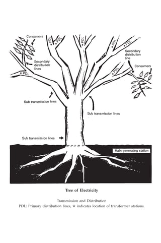
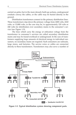
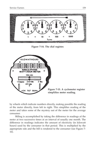
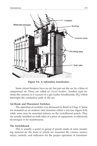
This document provides an overview of typical electrical power transmission and distribution systems. It describes how electricity is generated at high voltages around 20,000 volts, stepped up to higher transmission voltages like 138,000 volts, and transmitted through substations where it is stepped down through transformers to lower distribution voltages like 13,800 volts or 69,000 volts. It then explains how distribution circuits further step down the voltage through additional transformers to secondary voltages used by customers. The document uses an analogy that compares electricity flow through wires to water flow through pipes to explain how higher voltages allow electricity to be transmitted over greater distances with lower power losses.


![iv
Library of Congress Cataloging-in-Publication Data
Pansini, Anthony J.
Guide to electrical power distribution systems/Anthony J. Pansini.--6th ed.
p. cm.
Includes index.
ISBN: 0-88173-505-1 (print) — 0-88173-506-X (electronic)
1. Electric power distribution. 2. Electric power transmission. I. Title.
[TK3001.P284 2005]
621.319--dc22
2004056257
Guide to electrical power distribution systems, sixth edition/Anthony J. Pansini
©2005 by The Fairmont Press, Inc. All rights reserved. No part of this publication
may be reproduced or transmitted in any form or by any means, electronic or
mechanical, including photocopy, recording, or any information storage and
retrieval system, without permission in writing from the publisher.
Published by The Fairmont Press, Inc.
700 Indian Trail
Lilburn, GA 30047
tel: 770-925-9388; fax: 770-381-9865
http://www.fairmontpress.com
Distributed by Marcel Dekker/CRC Press
2000 N.W. Corporate Blvd.
Boca Raton, FL 33431
tel: 800-272-7737
http://www.crcpress.com
Printed in the United States of America
10 9 8 7 6 5 4 3 2 1
0-88173-505-1 (The Fairmont Press, Inc.)
0-8493-3666-X (Dekker/CRC Press)
While every effort is made to provide dependable information, the publisher,
authors, and editors cannot be held responsible for any errors or omissions.](https://image.slidesharecdn.com/e-guidetoelectricalpowerdistributionsystems-220906033327-812c61f0/85/E-guide_to_electrical_power_distribution_systems-pdf-6-320.jpg)


![4 Electrical Power Distribution Systems
In the pictorial rendition, note that the generator produces
20,000 volts. This, however, is raised to 138,000 volts for the long
transmission journey. This power is conducted over 138,000-volt (138
kV) transmission lines to switching stations located in the important
load area served. These steel tower or wood frame lines, which con-
stitute the backbone of the transmission system, span fields and rivers
in direct cross country routes. When the power reaches the switching
stations, it is stepped down to 69,000 volts (69 kV) for transmission in
smaller quantities to the substations in the local load areas. (In some
cases it might be stepped down to 13,800 volts [13.8 kV] for direct
distribution to local areas.) Transmission circuits of such voltages usu-
ally consist of open wires on wood or steel poles and structures in
outlying zones (along highways, for example) where this type of con-
struction is practicable.
Other transmission-line installations can provide an interchange
of power between two or more utility companies to their mutual ad-
vantage. Sometimes, in more densely populated areas, portions of
these transmission lines may consist of high-voltage underground sys-
tems operating at 69,000, 138,000, 220,000, 345,000, 500,000, and
750,000 volts.
WATER-CURRENT ANALOGY
The flow of electric current may be visualized by comparing it with
the flow of water. Where water is made to flow in pipes, electric current
is conducted along wires.
To move a definite amount of water from one point to another in
a given amount of time, either a large-diameter pipe may be used and
a low pressure applied on the water to force it through, or a small-diam-
eter pipe may be used and a high pressure applied to the water to force
it through. While doing this it must be borne in mind that when higher
pressures are used, the pipes must have thicker walls to withstand that
pressure (see Figure 1-3).
The same rule applies to the transmission of electric current. In this
case, the diameter of the pipe corresponds to the diameter of the wire
and the thickness of the pipe walls corresponds to the thickness of the
insulation around the wire, as shown in Figure 1-4.](https://image.slidesharecdn.com/e-guidetoelectricalpowerdistributionsystems-220906033327-812c61f0/85/E-guide_to_electrical_power_distribution_systems-pdf-16-320.jpg)


![28 Electrical Power Distribution Systems
However, if there is an unequal span of wire on one side creating a strain
or if the soil conditions are poor, the pole must be set 8-1/2 feet deep.
POLE GAINS
Gaining is the process of shaving or cutting a pole to receive the
crossarms. In some cases this consists of Cutting a slightly concaved
recess 1/2 inch in depth [see Figure 2-10(a)] so that the arm cannot rock.
The recess in the pole is now considered unnecessary. Instead the
surface of the pole where the crossarm will be attached is merely flat-
tened to present a flat smooth area. This is called “slab gaining,” see
Figure 2-10(b). The cross arm is then fastened to the pole with a through
bolt. Two flat braces are attached to secure the arm. Some poles have two
crossarms mounted one on either side of the pole. These are known as
double arms. When double arms are installed, the pole is gained on one
side only. A double gain would tend to weaken the pole and is unnec-
essary since the tightening of the through-bolt causes the arm on the
back of the pole to bite into the surface.
Pole steps for the lineworker to climb are usually installed at the
same time that the pole is roofed and gained, where these are considered
to be desirable.
Table 2-3 Approximate Typical Pole Setting Depths
————————————————————————————————
Setting Depths Setting Depths at Points
on Straight Lines, of Extra Strain or with
Length of Pole Overall Curbs, and Corners Poor Soil Conditions
————————————————————————————————
30 ft and under 5 ft 0 in. 5 ft 6 in.
35 ft 5 ft 6 in. 6 ft 0 in.
40 ft 6 ft 0 in. 6 ft 6 in.
45 ft 6 ft 6 in. 7 ft 0 in.
50 ft 7 ft 0 in. 7 ft 6 in.
55 ft 7 ft 6 in. 8 ft 0 in.
60 ft 8 ft 0 in. 8 ft 6 in.
65 ft 8 ft 0 in. 8 ft 6 in.
70 ft and over Special Setting Specified
————————————————————————————————](https://image.slidesharecdn.com/e-guidetoelectricalpowerdistributionsystems-220906033327-812c61f0/85/E-guide_to_electrical_power_distribution_systems-pdf-40-320.jpg)
![Conductor Supports 29
CROSSARMS
The woods most commonly used for crossarms are Douglas Fir or
Longleaf Southern Pine because of their straight grain and durability.
The top surface of the arm is rounded [see Figure 2-11 (a)] so that rain
or melting snow and ice will run off easily.
The usual cross-sectional dimensions for distribution crossarms are
3-1/2 inches by 4-1/2 inches; their length depending on the number and
spacing of the pins. Heavier arms of varying lengths are used for special
purposes, usually for holding the heavier transmission conductors and
insulators. Four-pin [see Figure 2-11 (b)], six-pin, and eight-pin arms are
standard for distribution crossarms, the six-pin arm being the most com-
mon. Where unusually heavy loading is encountered, as at corner or
junction poles, double arms, that is, one on each side of the pole may be
required as shown on Figure 2-11 (c). Again, the emphasis on appear-
Figure 2-10 (a). Recess-gained pole and (b) slab-gained pole. Measure-
ments are for poles 25 to 60 feet long. For poles 65 feet long and over,
slab gain should total 73 inches in length.](https://image.slidesharecdn.com/e-guidetoelectricalpowerdistributionsystems-220906033327-812c61f0/85/E-guide_to_electrical_power_distribution_systems-pdf-41-320.jpg)


![Insulators and Conductors 39
made of one piece of porcelain and its mounting bolt or bracket is an
integral part of the insulator.
Advantage of Pin or Post over Suspension Insulators
The most commonly used insulators are the pin or post type and
the suspension (or hanging) type [see Figure 3-4(c)]. A third type, the
strain insulator, is a variation of the suspension insulator and is de-
signed to sustain extraordinary pulls. Another type, the spool insulator,
is used with secondary racks and on service fittings.
The main advantage of the pin or post-type insulator is that it is
cheaper. Also, the pin or post insulator requires a shorter pole to achieve
the same conductor above the crossarm while the suspension insulator
suspends it below the crossarm.
Figure 3-3. Two styles of low-voltage porcelain insulator.
Figure 3-4 (a). Pin and (b) post-type insulators.](https://image.slidesharecdn.com/e-guidetoelectricalpowerdistributionsystems-220906033327-812c61f0/85/E-guide_to_electrical_power_distribution_systems-pdf-51-320.jpg)


![Insulators and Conductors 45
copper to determine their economic value as electrical conductors.
Aluminum-steel or copper-steel combinations and aluminum have
become popular for conductors in particular circumstances. Aluminum
alloys are also used as conductors.
Copper Conductors
Copper is used in three forms: hard drawn, medium-hard drawn,
and soft drawn (annealed). Hard-drawn copper wire has the greatest
strength of the three and is, therefore, mainly used for transmission cir-
cuits of long spans (200 ft or more). However, its springiness and inflex-
ibility make it hard to work with [see Figure 3-11 (a)].
Soft-drawn wire is the weakest of the three [Figure 3-11 (b)]. Its use
is limited to short spans and for tying conductors to pin-type insulators.
Since it bends easily and is easy to work with, soft-drawn wire is used
widely for services to buildings and some distribution circuits. Practice,
however, has been toward longer distribution circuit spans and use of
medium-hard-drawn copper wire.
Figure 3-10. All conductors are compared to copper. (a) Steel, strong,
but poor conductor. (b) Copper, an all-around good, durable conductor
for its price. (c) Aluminum, light, durable, rust-proof, but only 70% as
good a conductor. (d) Silver, better conductor, too expensive, and
mechanically weak.](https://image.slidesharecdn.com/e-guidetoelectricalpowerdistributionsystems-220906033327-812c61f0/85/E-guide_to_electrical_power_distribution_systems-pdf-57-320.jpg)
![46 Electrical Power Distribution Systems
Aluminum and ACSR Conductors
Aluminum is used because of its light weight as illustrated in Fig-
ure 3-12, which is less than one third that of copper. It is only 60 to 80
percent as good a conductor as copper and only half as strong as copper.
For these reasons it is hardly ever used alone, except for short distribu-
tion spans. Usually the aluminum wires are stranded on a core of steel
wire. Such steel reinforced aluminum wire has great strength for the
weight of the conductor and is especially suitable for long spans. Trans-
mission lines often consist of aluminum conductors steel reinforced
(ACSR).
Steel Conductors
Steel wire is rarely used alone. However, where very cheap con-
struction is needed, steel offers an economic advantage. Because steel
wire is three to five times as strong as copper, it permits longer spans
and requires fewer supports. However, steel is only about one tenth as
good a conductor as copper and it rusts rapidly [see Figure 3-13(a)]. This
rusting tendency can be counteracted (so that steel wire will last longer)
by galvanizing, that is, by the application of a coat of zinc to the surface.
Copperweld or Alumoweld Conductors
The main disadvantages of steel are a lack of durability and con-
Figure 3-11 (a). Hard-drawn copper is strong but inflexible and
springy. It is used for long spans. (b) Soft-drawn (annealed) copper is
weak but easy to handle. It is used for service and some distribution
circuits.
(a) (b)](https://image.slidesharecdn.com/e-guidetoelectricalpowerdistributionsystems-220906033327-812c61f0/85/E-guide_to_electrical_power_distribution_systems-pdf-58-320.jpg)
![Insulators and Conductors 47
ductivity. On the other hand, steel is cheap, strong, and available. These
advantages made the development of copper-clad or aluminum-clad
steel wire [see Figure 3-13(b)] most attractive to the utility companies. To
give steel wire the conductivity and durability it needs, a coating of
copper is securely applied to its outside. The conductivity of this clad
steel wire can be increased by increasing the coating of copper or alumi-
num. This type of wire, known as Copperweld or Alumoweld is used for
guying purposes and as a conductor on rural lines, where lines are long
and currents are small.
Conductor Stranding
As conductors become larger, they become too rigid for easy han-
dling. Bending can damage a large solid conductor. For these practical
reasons, the stranded conductor was developed (see Figure 3-14). A
stranded conductor consists of a group of wires twisted into a single
Figure 3-12. The advantage of aluminum as a conductor is its light
weight-less than one third the weight of copper.](https://image.slidesharecdn.com/e-guidetoelectricalpowerdistributionsystems-220906033327-812c61f0/85/E-guide_to_electrical_power_distribution_systems-pdf-59-320.jpg)


![Line Equipment 61
If it is necessary to change the taps when the transformer cannot be
disconnected from the circuit, tap changers under-load are used. They
involve the use of an autotransformer and an elaborate switching ar-
rangement. The information regarding the switching sequence must be
furnished with each transformer. Tap changers can function automati-
cally if designed with additional control circuits: automatic tap changes
are used for high-power transformers, and for voltage regulators.
Mounting Distribution Transformers
Distribution transformers are almost always located outdoors
where they are hung from crossarms, mounted on poles directly (see
Figure 4-5) or placed on platforms. In general, transformers up to 75 kVA
size are mounted directly to the pole or on a crossarm and larger size
transformers (or groups of several transformers) are placed on platforms
or mounted on poles in banks or clusters.
How a transformer is mounted is a matter of considerable impor-
tance. Remember that the distribution transformer must stay put and
continue functioning even in the midst of violent winds, pouring rain,
freezing cold, sleet, and snow. Besides weather, there is danger of the
pole itself being hit by a carelessly driven vehicle.
Modern pole-mounted transformers [see Figure 4-6(a)] have two
lugs welded directly on the case. These lugs engage two bolts on the
pole as shown in Figure 46(b) from which the whole apparatus hangs
securely. This method, which is known as direct mounting eliminates the
need for crossarms and hanger irons (as was done in the past), thus
saving a considerable amount of material and labor.
In the past, transformers were hung from crossarms by means of
hanger irons, which were two flat pieces of steel with their top ends bent
into hooks with squared sides (see Figure 4-7). The transformer was
bolted to these pieces of steel, the assembly was raised slightly above the
crossarm and then lowered so that the hooks on the hanger irons would
engage the crossarm. Many such installations still exist.
A transformer should not be mounted on a junction pole (a pole
supporting lines from three or more directions) as this makes working
on such a pole more hazardous for the worker.
Where transformers cannot be mounted on poles because of size or
number, they may be installed on an elevated platform [Figure 4-8(a)] or
a ground-level pad [Figure 4-8(b)]. Platforms are built in any shape or
size required to suit the particular need. They are usually constructed of](https://image.slidesharecdn.com/e-guidetoelectricalpowerdistributionsystems-220906033327-812c61f0/85/E-guide_to_electrical_power_distribution_systems-pdf-73-320.jpg)


![70 Electrical Power Distribution Systems
LIGHTNING OR SURGE ARRESTERS
A lightning arrester is a device that protects transformers and other
electrical apparatus from voltage surges. These surges can occur either
because of lightning or improper switching in the circuit. The lightning
arrester provides a path over which the surge can pass to ground as
shown in Figure 4-16(a), before it has a chance to attack and seriously
damage [see Figure 4-16(b)] the transformer or other equipment.
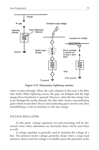
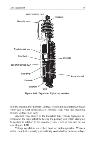
The elementary lightning arrester consists of an air gap (illustrated
in Figure 4-17) in series with a resistive element. The voltage surge
causes a spark which jumps across the air gap, passes through the resis-
tive element (silicon carbide, for example) which is usually a material
Figure 4-14. Open-type fuse cutout.](https://image.slidesharecdn.com/e-guidetoelectricalpowerdistributionsystems-220906033327-812c61f0/85/E-guide_to_electrical_power_distribution_systems-pdf-82-320.jpg)


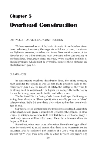


![Overhead Construction 93
as shown in Figure 5-6(a) puts a much greater strain on the poles which
hold it at either end. Adding the weight of wet clothes to a tightly strung
line might even pull the poles out of place. However, using a little more
rope and allowing the clothesline to dip a little [see Figure 5-6(b)] would
relieve this pull considerably. This dip is what is called sag.
The same applies to stringing wire. When metallic wire is strung
tightly, it produces a greater strain on the insulator pins and on the pole.
Scientific sag is an important factor in stringing wire.
How the Weather Affects Conductors
As previously mentioned, a line sags more in hot weather and less
in cold weather. The reason for this is because conductors expand in hot
weather; in other words the length of the conductor increases as the
temperature increases. It follows that in cold weather the metallic con-
ductor will be shorter than in warm weather. If the wire were strung
without sag, it would snap during cold weather. On the other hand,
there is a chance a wire strung with too much sag would dip below the
Figure 5-4. Where possible, trees are trimmed.
Figure 5-5. Tree wire.](https://image.slidesharecdn.com/e-guidetoelectricalpowerdistributionsystems-220906033327-812c61f0/85/E-guide_to_electrical_power_distribution_systems-pdf-105-320.jpg)


![Overhead Construction 99
Types of Guys
In situations where an anchor guy is impractical because of cross-
ing a road, a span guy is used. In this form of guying, the guy wire
extends from the top of the pole to be guyed to the top of another pole
across the street, at approximately the same height. A span guy merely
transfers some strain from one pole to another [see Figure 5-13(a)].
Hence, a head guy or anchor guy [see Figure 5-13(b)] is usually used
with a span guy.
The head guy is a variation of the span guy, differing in that the
wire runs to a point somewhere below the top of the sustaining pole.
This type is rarely used in crossing a highway.
Specifications have been set up regarding clearances for guys, just
as for conductors.
When it would be difficult to achieve these clearances, a stub guy
is used [see Figures 5-13(c) and 5-13(d)]. A stub is just a piece of wood
to which the guy wire is attached. The guy must be attached to the stub
at some point 8 feet or more above ground. The stub guy wire must
allow enough clearance for traffic.
Figure 5-11. Screw-type guy anchors (a), and installing anchors (b).](https://image.slidesharecdn.com/e-guidetoelectricalpowerdistributionsystems-220906033327-812c61f0/85/E-guide_to_electrical_power_distribution_systems-pdf-111-320.jpg)

![Overhead Construction 101
Should it prove necessary to guy a pole on private property, some
problems may arise. Sometimes owners object to a stub or anchor being
planted on their land, but they may approve of a guy wire being at-
tached to a tree [see Figure 5-13(e)]. This is certainly not recommended
practice, because a live tree is a very undependable sustainer. However,
there are cases where there is no other practical solution.
Where Guys Should Be Used
When a conductor terminates (dead-ends) on a pole, as shown in
Figure 5-14(a), a guy is attached to the pole to counteract the pull of the
conductors. In case of heavy construction where one guy is inadequate,
a guy may be used on the pole next to the last one.
Figure 5-13. How a span guy is used (a) and (b).](https://image.slidesharecdn.com/e-guidetoelectricalpowerdistributionsystems-220906033327-812c61f0/85/E-guide_to_electrical_power_distribution_systems-pdf-113-320.jpg)
![102 Electrical Power Distribution Systems
Sometimes there is the problem of a partial dead-end. In other
words, more wires are dead-ended on one side of a crossarm than on the
other. A guy is run from the side of the crossarm undergoing the worst
strain to the adjacent pole [see Figure 5-14(b)].
Corners are treated like dead-ends; however, since the pull on the
pole is in two directions, it is wise to use two guys to counteract the pull
in two directions, counterbalancing the pull of one set of wires [see Fig-
ure 5-14(c)].
When the conductors form an angle, the pole is submitted to an
additional stress. To balance these forces, side guys are attached as
shown in Figure 5-14(d) to the poles to take up the side pull.
Figure 5-13. (c) Straight and (d) raked stub guy.
Figure 5-13. (e) Tree used as stub guy. Not recommended practice.](https://image.slidesharecdn.com/e-guidetoelectricalpowerdistributionsystems-220906033327-812c61f0/85/E-guide_to_electrical_power_distribution_systems-pdf-114-320.jpg)
![Overhead Construction 103
When a pole is located on the slope of a hill, a head guy or an
anchor guy can be used to counteract the down-hill pull of conductors
[see Figure 5-14(e)].
When a branch line shoots from a pole, the weight of the branch
conductors causes a side pull. This side pull is counterbalanced by side
guys [see Figure 5-14(f)].
Figure 5-14. (a) Guy installed on terminal or dead-end pole.
Figure 5-14. (b) Crossarm guy compensates unbalanced pull on
crossarm.](https://image.slidesharecdn.com/e-guidetoelectricalpowerdistributionsystems-220906033327-812c61f0/85/E-guide_to_electrical_power_distribution_systems-pdf-115-320.jpg)
![104 Electrical Power Distribution Systems
When a line may be subjected to storms or other strong atmo-
spheric disturbances, storm guys are placed at regular intervals in the
line. Generally, four guys are used for this purpose-two line guys and
two side guys. All four guys are fastened to the same pole [see Figure
5-14(g)]. Line guys are attached from one pole to the other, thus doing
away with the necessity for anchors. Should one pole fail, damage will
be limited to the relatively small area between adjacent storm-guyed
poles, rather than have the entire line fall, pole after pole.
Other Methods of Sustaining Poles
Sometimes it is necessary to set poles in marshy or swampy land.
Since the ground does not hold the pole firmly in such a situation, a guy
is necessary. However, it is likely that the use of head or anchor guys
might be impractical or impossible for one reason or another. For ex-
ample, the ground might be too marshy to hold any pole, even a stub;
or there might be no available space for an anchor.
Here are some possible solutions.
Figure 5-14. (c) Two anchor guys sustaining a corner pole.
Figure 5-14. (d) Line making an angle.](https://image.slidesharecdn.com/e-guidetoelectricalpowerdistributionsystems-220906033327-812c61f0/85/E-guide_to_electrical_power_distribution_systems-pdf-116-320.jpg)
![Overhead Construction 105
The pole can be propped up with a push-brace [see Figure 5-15(a)].
Before a pole is planted in marshy land, an empty oil drum or a
tube of corrugated iron is set in the ground [see Figure 5-15(b)]. After the
pole is dropped in, the drum may be backfilled with dirt or concrete.
The area necessary for guying can be minimized by using a side-
walk guy [see Figure 5-15(c)].
Cribbing is necessary in marshy land when the pole must resist an
unbalanced load. It is also used in crowded or residential areas when
Figure 5-14. (c) Head guys counteract the pull on poles installed on a
steep hillside.
Figure 5-14. (f) A guy is used to counteract the side pull of a branch
line connection.](https://image.slidesharecdn.com/e-guidetoelectricalpowerdistributionsystems-220906033327-812c61f0/85/E-guide_to_electrical_power_distribution_systems-pdf-117-320.jpg)
![106 Electrical Power Distribution Systems
exposed guys would be dangerous, unsightly, or impractical. Cribbing
involves placing logs, stones, or other supports at the bottom of the pole
on one side and near the surface on the earth on the other side [Figure
5-15(d)). These objects counteract the strain being put on the pole from
one direction. As in the case of anchors, utility companies have found it
economical in some cases to replace logs with another cribbing device
called a pole key [see Figure 5-15(e)].
Joint Construction
For economy and appearance, it is often preferable to use one pole
for both power and communication lines (see Figure 5-16). This is
known as joint construction. Besides the power companies, telephone
companies are the biggest users of poles.
Telephone facilities may consist of open wires on crossarms or of
a cable supported on a “messenger.” Besides the power and telephone
companies, the fire department, the police department, the Coast Guard,
the railroad, Western Union, cable TV systems, and even private citizens
may have wires strung on the poles.
All these extra wires add a new factor to the problem of line de-
sign. Sometimes extra heavy poles or additional guying become neces-
sary, especially in the case of telephone cables. Distance must be
Figure 5-14. (g) Two methods of installing storm guys.](https://image.slidesharecdn.com/e-guidetoelectricalpowerdistributionsystems-220906033327-812c61f0/85/E-guide_to_electrical_power_distribution_systems-pdf-118-320.jpg)


![Service Factors 161
available for checking, until the meter
is next read, when the lever or
plunger which returns the “floating”
hand to zero causes the new maxi-
mum demand to be added to the
original reading: the new reading will
then be greater than the previous one
by the current period’s maximum de-
mand.
SERVICE EQUIPMENT
When the meter is placed in-
doors, the service conductors coming into the consumers’ premises ter-
minate in a cut-out box. This is merely a point at which the service wires
can be disconnected from the house wiring. It may be a switch and each
conductor may or may not be fused. From this point, the wires extend
to another box associated with the meter. This second box holds the
terminals for the meter and a special switch which permits testing the
meter without interrupting service. Where only one meter of small size
is installed, the service cut-out box, the meter terminal, and test box may
be combined in one cabinet. In any case, these boxes are all locked with
a seal which must be broken when they are opened. This is done to
prevent the theft of electricity by by-passing or tampering with the
meter. In more recent installations, the positions of these two boxes are
reversed, the box associated with the meter comes first and the switch
box next (see Figure 7-18).
The equipment to this point, with the exception of the meter, may
or may not be owned by the consumer. In all cases, however, the utility
company owns the meter.
The service from this point is then connected to a distribution
panel which supplies the circuit to the various parts of the consumer’s
premises. These circuits are usually protected at the distribution panel
[see Figure 7-19(a)] so that in the event of an overload, or an accidental
short circuit in one of the circuits, only a fuse or breaker will operate and
service to the remaining parts of the consumers’ premises will not be
interrupted. Most installations today provide that this panel may be
contained in the same box as the switch.
Figure 7-17. The register of a
demand meter—for large
consumers.](https://image.slidesharecdn.com/e-guidetoelectricalpowerdistributionsystems-220906033327-812c61f0/85/E-guide_to_electrical_power_distribution_systems-pdf-173-320.jpg)
![162 Electrical Power Distribution Systems
When the meter is placed outdoors, there is no need for the box
providing a point to connect or test the meter. The remaining distribu-
tion panel is still required and is usually installed inside the consumer’s
premises.
For safety purposes, one conductor is connected to ground, usually
to a driven rod or pipe or other metallic structure [see Figure 7-19(b)].
This is done so that if an accidental contact of an energized conductor
takes place, the energy is conducted to the ground and possibility of
electric shock reduced. For this reason, a fuse is never placed in the cir-
cuit of this “neutral” or ground conductor.
REMOTE METER READING AND DEMAND CONTROL
Electronic developments that have made e-mail (and the Internet)
inexpensive and universal means of communication have also made
practical the remote reading of consumer’s meters. Periodic inquiry
Figure 7-18. An enclosed switch box.](https://image.slidesharecdn.com/e-guidetoelectricalpowerdistributionsystems-220906033327-812c61f0/85/E-guide_to_electrical_power_distribution_systems-pdf-174-320.jpg)


![Substations 165
165
Chapter 8
Substations
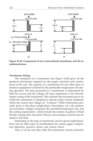
FUNCTIONS OF A SUBSTATION
Substations serve as sources of energy supply for the local areas
of distribution in which they are located. Their main functions as
shown in Figure 8-1 are to receive energy transmitted at high voltage
from the generating stations, reduce the voltage to a value appropri-
ate for local use, and provide facilities for switching. Substations have
some additional functions. They provide points where safety devices
may be installed to disconnect circuits or equipment in the event of
trouble. Voltage on the outgoing distribution feeders can be regulated
at a substation. A substation is a convenient place to make measure-
ments to check the operation of various parts of the system. Street
lighting equipment as well as on-and-off controls for street lights can
be installed in a substation though this is a diminishing function.
Some substations are simply switching stations where different
connections can be made between various transmission lines.
TYPES OF SUBSTATIONS
Some substations are entirely enclosed in buildings as shown in
Figure 8-2(a), while others are built entirely in the open [see Figure 8-
2(b)], for example, unit substations. In this type, all the equipment is
assembled into one metal clad unit usually enclosed by a fence. Other
substations have step-down transformers, high-voltage switches and oil
circuit breakers, and lightning arresters located just outside the substa-
tion building within which are located the distribution and street light-
ing facilities.
Sites for substations are generally selected so that the stations will
be as near as possible to the load center of the distribution areas which
they are intended to serve. Availability of land, cost, local zoning laws,](https://image.slidesharecdn.com/e-guidetoelectricalpowerdistributionsystems-220906033327-812c61f0/85/E-guide_to_electrical_power_distribution_systems-pdf-177-320.jpg)


![196 Electrical Power Distribution Systems
(having a positive electric charge). Around this nucleus spin electrons
(having a negative electric charge) in various orbits. The electrons in the
outer orbit of the atom may leave that orbit and move from atom to
atom in a substance. These electrons are called free electrons, and nor-
mally move in all different directions. However, when a voltage is ap-
plied across a wire, the free electrons flow in one general direction,
called the current flow. Materials having many free electrons are called
conductors, and for a given amount of voltage will provide a large cur-
rent flow.
Materials having few free electrons [see Figure 10-2(b)] are called
insulators and for a given amount of voltage will provide little or no
current flow. Typical good electrical conductors are copper and alumi-
num; good insulators are mica, porcelain, glass, and wood.
Resistance
Resistance is essentially the opposition offered by a substance to the
flow of electric current. Remember that a conductor is made of a mate-
rial whose atomic structure has a large number of free electrons. Because
of the greater number of free electrons in their atomic structure, some
conductors allow electric current to flow more readily than others. Re-
Figure 10-1. Comparison of water and electric currents. (a) Flow iden-
tifies water in motion. (b) Electric current identifies electricity in
motion.](https://image.slidesharecdn.com/e-guidetoelectricalpowerdistributionsystems-220906033327-812c61f0/85/E-guide_to_electrical_power_distribution_systems-pdf-208-320.jpg)

![198 Electrical Power Distribution Systems
a closed path. These closed paths can be arranged in several ways—in
series, parallel, and series-parallel—and are referred to as circuits, or
electric circuits. A series circuit [see Figure 10-4(a)] is formed by connect-
ing a storage battery to a number of lamps connected as shown. If for
any reason one of the lamps goes out, there is no longer a closed electric
circuit and current will not flow.
If the same storage battery is taken and the lamps are connected
across each other, a parallel circuit is formed, shown in Figure 10-4(b). In
this arrangement should any one lamp go out, the remainder will re-
main lit. By combining lamps in series with those in parallel the series-
parallel circuit is formed, shown in Figure 10-4(c). In this circuit, the
series section has all the characteristics of the series circuit, and the
parallel section has the characteristics of the parallel circuit.
Difference of Pressure—
Difference of Potential-Voltage
In a water system that is made up of a water pump, water pipes,
and a valve (to turn the water on and off), water will flow only when the
pump is working. A pump enables a flow of water by virtue of the fact
that it creates a difference in pressure, causing the water to flow from a
point in the pipe at high pressure to a point in the pipe at a lower pres-
Figure 10-3. Resistance.](https://image.slidesharecdn.com/e-guidetoelectricalpowerdistributionsystems-220906033327-812c61f0/85/E-guide_to_electrical_power_distribution_systems-pdf-210-320.jpg)

![200 Electrical Power Distribution Systems
tor. This is the difference of electric pressure which will cause the elec-
trons in the conductor to move, that is, cause the current to flow in a
conductor. If the switch is placed in the off position, while the generator
is rotating, electric pressure or potential will be built up near the switch
terminals but no electric current will flow.
Electrical Quantities
Resistance, the opposition offered by a substance to the flow of
current; current, the flow of electrons through a conductor; and voltage,
the electrical pressure that forces current to flow through a resistance, all
have been discussed. These can now be discussed further regarding the
quantities or units in which each are measured. Resistance is measured
in ohms, current in amperes, and voltage in volts. These may be tied to-
gether with the basic statement that one ampere of current will flow
through a resistance of one ohm when a voltage of one volt is applied
across the resistance [see Figure 10-6(a)].
The unit of electrical power is the watt, with 746 watts considered
equal to one horsepower. The watt is equal to the current in a dc circuit
multiplied by the voltage applied to the circuit. Thus, if 100 amperes
flow in a circuit in which there is a 10-volt battery, the battery is supply-
ing 1000 watts of power. Another way of saying this is that the load is
consuming 1000 watts.
Electrical power consumed in the home or industry is measured in
Figure 10-5. Voltage is a measure of difference of potential.](https://image.slidesharecdn.com/e-guidetoelectricalpowerdistributionsystems-220906033327-812c61f0/85/E-guide_to_electrical_power_distribution_systems-pdf-212-320.jpg)
![Essentials of Electricity 201
terms of watt-hours. This is equal to the power consumed by a circuit
multiplied by the number of hours in which it was consumed. The in-
strument that measures this is called a watt-hour meter, and electric bills
are calculated on the basis of readings made on this meter [Figure 10-
6(b)].
While the basic units used in the measurement of electrical quan-
tities are the ohm, volt, ampere, and watt, these units often appear in
such large quantities that it would be inconvenient to speak in terms of
the basic unit. For example, approximately 6 volts may be obtained from
a storage battery, and 117 volts from a house electrical receptacle. How-
ever, when discussing high-voltage transformers and transmission lines
terms of 10,000 V, 50,000 V, and sometimes voltage in excess of 100,000
V are used. To simplify this, the prefix “kilo” is generally used for large
quantities. This indicates that the number should be multiplied by 1000.
Thus, a 10-kilovolt (kV) transformer is rated as being capable of han-
dling 10,000 V; similarly, 60 kV, 60 kW, and so on. In general notation,
abbreviate kilo and simply refer to “k,” hence, kV, kW, and so on.
Another commonly used prefix is the term “mega” or “meg”
which indicates that the number associated with it must be multiplied
by 1,000,000. In general use this term is too large to be associated with
either current or voltage, but is often used in connection with insulators
in such expressions as 1 megohm or 50 megohms.
Figure 10-6. Electrical quantities. (a) The power in this circuit is: 1 volt
×
×
×
×
× 1 ampere 1 watt. (b) In 1000 hours, a watt-hour meter would read 1
kilowatt hour.](https://image.slidesharecdn.com/e-guidetoelectricalpowerdistributionsystems-220906033327-812c61f0/85/E-guide_to_electrical_power_distribution_systems-pdf-213-320.jpg)


![208 Electrical Power Distribution Systems
Polyphase Voltage
The generation of a sine wave just described was the result of ro-
tating a coil of wire in the magnetic field set up by two poles of a mag-
net. In many cases it is more efficient and more economical to generate
a voltage by using many coils, each electrically insulated from each
other. When this is done, each coil produces a sine wave and the output
of such a generator appears as a series of sine waves each slightly dis-
placed. A sine wave may be divided into 360 degrees, and called a com-
plete cycle. Using this idea, if three coils are rotated in the magnetic
field, and if they are separated by 120 degrees, the sine-wave output will
be a series of sine waves each separated by 120 degrees [see Figure 10-
15(a) and 10-15(b)]. This is called three-phase voltage as against single-
phase voltage when a single coil is used.
In practice, the use of single or three-phase voltage is a matter of
Figure 10-15. Polyphase voltage. (a) Simplified diagram of 3-phase
generator and (b) output waveform of 3-phase generator.](https://image.slidesharecdn.com/e-guidetoelectricalpowerdistributionsystems-220906033327-812c61f0/85/E-guide_to_electrical_power_distribution_systems-pdf-220-320.jpg)


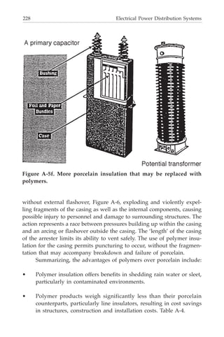
![214 Electrical Power Distribution Systems
prevent excessive rise of temperature and injury to the insulation about
the conductors. The cooling method used must be capable of maintain-
ing a sufficiently low average temperature. It must also be capable of
preventing an excessive temperature rise in any portion of the trans-
former, and the formation of “hot spots.” This is accomplished, for ex-
ample, by submerging the core and coils of the transformer in oil, and
allowing free circulation for the oil [Figure 10-21(a)]. Sometimes, for
reasons of safety, the use of oil as a cooling agent is prohibited. (Oil can
be a fire hazard.) In these situations, special fluids, known as “askarels”
can be used in place of oil. However, when using these substitutes, the
varnishes which are generally applied to the insulation of the coils must
be chosen carefully. For indoor use, in clean, dry locations, open dry-
type air cooling can be used [see Figure 10-21 (b)]. For outdoor or indoor,
use, a sealed dry type can be obtained.
Some transformers are cooled by other means: (a) by forced air or
air blast, (b) by a combination of forced oil and forced air, and (c) in
some special applications, by water cooling.
REVIEW QUESTIONS
1. Define electric current.
2. Name two materials that make good typical electrical conductors,
Figure 10-20. Transformer nameplate.](https://image.slidesharecdn.com/e-guidetoelectricalpowerdistributionsystems-220906033327-812c61f0/85/E-guide_to_electrical_power_distribution_systems-pdf-226-320.jpg)


![240 Electrical Power Distribution Systems
Film Disc Cutout
In the water circuit illustrated, it should be noted that if there is a
break in any of the connecting pipes, the water will drain out and the
action stops. A closed valve causes the same halt in action.
Similarly, if one of the lamps in a series circuit were to burn out, the
circuit would be interrupted and all the lights would go out. If the cur-
rent were to be allowed to flow into a burned out lamp in a series circuit,
it would be “dead-ended” there and not allowed to go any further. What
is needed is a device to automatically “detour” the current on to the
other lamps when one blows.
Such a device is known as a film disc cutout and is installed between
the prongs of the series socket as shown in Figure B-8. It consists essen-
tially of a thin piece of paper or insulation. Under normal conditions
while current flows through the lamps, the pressure or voltage between
the prongs of the lamp is insufficient to break down the piece of paper
which is now acting as an insulator. However, when the lamp burns out,
current can no longer flow and the pressure or voltage builds up on the
prongs of the lamp, until the film of paper is punctured [see Figure B-
8(b)]. Thus, the circuit is automatically closed, the burned out lamp
being short-circuited and the rest of the lamps in the circuit remain lit.
A socket for series lighting is shown in Figure B-8(c). The prongs
and the film cutout are indicated. For multiple lighting, a socket of the
Figure B-7. Series street-lighting circuit.](https://image.slidesharecdn.com/e-guidetoelectricalpowerdistributionsystems-220906033327-812c61f0/85/E-guide_to_electrical_power_distribution_systems-pdf-252-320.jpg)


![Street Lighting 243
Photocell-Controlled Relay
On and off control of street lights is often accomplished through
the use of a photoelectric-controlled relay. Older systems use a photo-
tube [Figure B-11 (a)], which consists basically of a pair of electrodes
contained in an evacuated envelope. When properly connected into a
circuit, these electrodes allow more current to flow in the tube as the
intensity of the incident light increases. The phototube circuit is inte-
grated with a control circuit which incorporates a relay. When the cur-
rent in the phototube circuit reaches a predetermined value, the relay in
the control circuit functions and causes the lights to go out. As the day
darkens, the reverse action takes place. The current in the phototube
circuit decreases until another predetermined value is reached. Then the
relay in the control circuit functions and the lights are turned on.
Newer systems use a solid-state photocell [Figure B-11 (b)] instead
of a phototube. The operation is essentially the same as that of the pho-
Figure B-10. Astronomical time switch.](https://image.slidesharecdn.com/e-guidetoelectricalpowerdistributionsystems-220906033327-812c61f0/85/E-guide_to_electrical_power_distribution_systems-pdf-255-320.jpg)


![248 Electrical Power Distribution Systems
duced by the flow of electricity.
The fluorescent lamp unit generally consists of 2 electrodes, one
at either end of the tube. These electrodes emit and receive, receive
and emit electrons between them in an operation that resembles a
tennis match. A drop of mercury [see Figure B-17(b)] is added inside
the tube to make it start or light up initially. A “ballast” device is in-
cluded in the circuit to permit the electrodes to reach sufficient volt-
age to start the arc going across the tube. Fluorescent tubes can be
made to shed other colors besides the well known blue-white.
Discharge Lamps
Where high-intensity illumination is required (along highways,
for example) a discharge lamp fits the bill. The primary advantage of
a gaseous discharge lamp is that it can give out much more light for
its size than an incandescent lamp of comparable size. Sodium and
mercury are commonly used materials for discharge lamps (see Fig-
ure B-18). Designers have discovered that all-around these are the
most economical chemicals with respect to supplying the proper tem-
perature, voltage, and pressure.
In the mercury-vapor lamp, the mercury is vaporized by the
current flowing through the lamp. (Again the current is controlled by
Figure B-16. Basic construction of the incandescent lamp,](https://image.slidesharecdn.com/e-guidetoelectricalpowerdistributionsystems-220906033327-812c61f0/85/E-guide_to_electrical_power_distribution_systems-pdf-260-320.jpg)