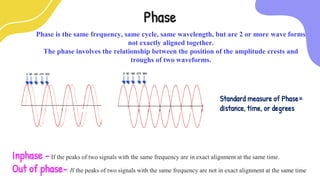
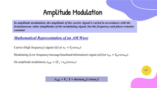
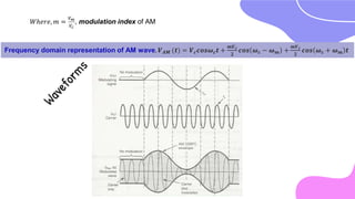
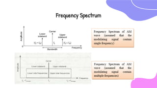
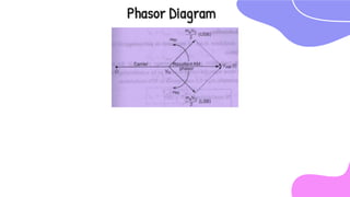
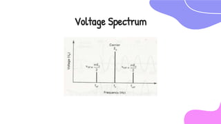
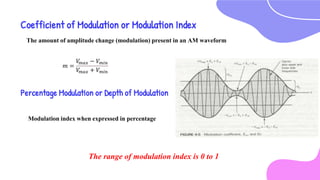
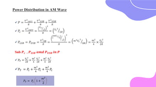
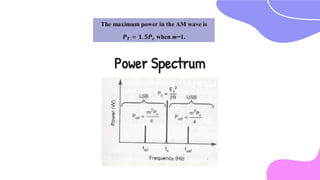
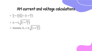
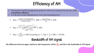
Amplitude Modulation
To achieve modulation, we need two signals, carrier (high frequency) and message
(low frequency) signals
 In Continuous Wave (CW) modulation schemes, the carrier is a sinusoid.
 The three parameters of a sinusoidal carrier that can be varied are:
 Amplitude,
 Frequency
 Phase
 According to parameters: Types of Modulation
 Amplitude Modulation (AM),
 Frequency Modulation (FM) and
 Phase Modulation (PM).
Amplitude
Amplitude is the height, force or power of the wave
Frequency and Phase remains constant, however the height of the wave is
dynamic based on the power of the wave
 The higher power, or amplitude, the higher the wave form peeks.
 The lower the power, or amplitude, the lower the wave form peeks
Standard measure of amplitude = Volts
Frequency
Frequent, consistent, and repetitive
Frequency - Number of times a specified event occurs within a
specified time interval
Standard measure of Frequency = Hertz or
cycles per seconds
1. AM Radio: 535-1605 kHz
2. FM Radio: 88-108 MHz
3. TV Broadcasting: VHF Band – 41-68 MHz and 174-230 MHz; UHF
band -470-890MHz
4. Microwave & Satellite Signal – Several GHz
5. Infrared & Fiber Optic Signals – 200 to 300 THz
Frequencies used for
various applications
Phase
Phase is the same frequency, same cycle, same wavelength, but are 2 or more wave forms
not exactly aligned together.
The phase involves the relationship between the position of the amplitude crests and
troughs of two waveforms.
Inphase -If the peaks of two signals with the same frequency are in exact alignment at the same time.
Out of phase- If the peaks of two signals with the same frequency are not in exact alignment at the same time
Standard measure of Phase=
distance, time, or degrees
In amplitude modulation, the amplitude of the carrier signal is varied in accordance with the
instantaneous value (amplitude) of the modulating signal, but the frequency and phase remains
constant
Mathematical Representation of an AM Wave
Amplitude Modulation
Carrier (High frequency) signal c t or 𝑣𝑐 = 𝑉
𝑐𝑐𝑜𝑠𝜔𝑐𝑡
Modulating (Low frequency/message/baseband/information) signal, m t or 𝑣𝑚 = 𝑉
𝑚𝑐𝑜𝑠𝜔𝑚𝑡
On amplitude modulation, 𝑣𝐴𝑀 = 𝑉𝑐+𝑣𝑚)𝑐𝑜𝑠𝜔𝑐𝑡
𝒗𝑨𝑴 = 𝑽𝒄 𝟏 + 𝒎𝒄𝒐𝒔𝝎𝒎𝒕 𝒄𝒐𝒔𝝎𝒄𝒕
𝑊ℎ𝑒𝑟𝑒, 𝑚 =
𝑉𝑚
𝑉𝑐
, modulation index of AM
Frequency domain representation of AM wave, 𝑽𝑨𝑴 𝒕) = 𝑽𝒄𝒄𝒐𝒔𝝎𝒄𝒕 +
𝒎𝑽𝒄
𝟐
𝒄𝒐𝒔 𝝎𝒄 − 𝝎𝒎 +
𝒎𝑽𝒄
𝟐
𝒄𝒐𝒔 𝝎𝒄 + 𝝎𝒎 𝒕
Frequency Spectrum
Phasor Diagram
Voltage Spectrum
Coefficient of Modulation or Modulation Index
𝑚 =
𝑉
𝑚𝑎𝑥 − 𝑉𝑚𝑖𝑛
𝑉
𝑚𝑎𝑥 + 𝑉𝑚𝑖𝑛
The amount of amplitude change (modulation) present in an AM waveform
Percentage Modulation or Depth of Modulation
Modulation index when expressed in percentage
The range of modulation index is 0 to 1
 Under modulation (m < 1 or Vm < Vc).
 Critical modulation (m =1 or Vm = Vc).
 Over modulation (m >1 or Vm > Vc).
Degree of Modulation
 𝑃 =
𝑉2
𝑐𝑎𝑟𝑟
𝑅
+
𝑉2
𝐿𝑆𝐵
𝑅
+
𝑉2
𝑈𝑆𝐵
𝑅
 𝑃𝑐 =
𝑉2
𝑐𝑎𝑟𝑟
𝑅
=
𝑉𝑐
2
2
𝑅
= 𝑉𝑐
2
2𝑅
 𝑃𝐿𝑆𝐵 = 𝑃𝑈𝑆𝐵 =
𝑉2
𝑆𝐵
𝑅
=
𝑚𝑉𝑐
2
2
2
𝑅
= 𝑚2𝑉𝑐
2
8𝑅 =
𝑚2
4
×
𝑉𝑐
2
2𝑅
Power Distribution in AM Wave
𝑃𝑇 = 𝑃𝑐 1 +
𝑚2
2
Sub 𝑷𝒄 , 𝑷𝑳𝑺𝑩 𝒂𝒎𝒅 𝑷𝑼𝑺𝑩 𝒊𝒏 𝑷
 𝑃𝑇 =
𝑉𝑐
2
2𝑅
+
𝑚2
4
𝑉𝑐
2
2𝑅
+
𝑚2
4
𝑉𝑐
2
2𝑅
𝑃𝑇 = 𝑃𝑐 +
𝑚2
4
𝑃𝑐 +
𝑚2
4
𝑃𝑐
Power Spectrum
The maximum power in the AM wave is
𝑷𝑻 = 𝟏. 𝟓𝑷𝒄 when m=1.

𝑃𝑇
𝑃𝑐
=
𝐼𝑇
2𝑅
𝐼𝑐
2𝑅
= 1 +
𝑚2
2
 𝐼𝑇 = 𝐼𝑐 1 +
𝑚2
2
 Similarly, 𝑉𝑇 = 𝑉
𝑐 1 +
𝑚2
2
AM current and voltage calculations
 %𝜂 =
𝑃𝑜𝑤𝑒𝑟 𝑖𝑛 𝑠𝑖𝑑𝑒𝑏𝑎𝑛𝑑𝑠
𝑇𝑜𝑡𝑎𝑙 𝑃𝑜𝑤𝑒𝑟
× 100 =
𝑃𝐿𝑆𝐵+𝑃𝑈𝑆𝐵
𝑃𝑇
× 100
 %𝜂 =
𝑚2𝑉𝑐
2
8𝑅 + 𝑚2𝑉𝑐
2
8𝑅
𝑉𝑐
2
2𝑅 1+
𝑚2
2
× 100
 %𝜂 =
𝑚2
2+𝑚2 × 100 Assuming m=1, %𝜂 =
1
3
× 100 = 33.3%.
Efficiency of AM
 The amount of useful message power present in AM wave is expressed by the term called
transmission efficiency
 It is the ratio of total sideband power to the total transmitted power
Bandwidth of AM signal
The difference between upper and lower side frequencies will be 2fm and this is the bandwidth of AM signal.
CREDITS: This presentation template was
created by Slidesgo, including icons by Flaticon,
infographics & images by Freepik
Thank You!

Ec8491 Communication Theory-Unit 1 - Amplitude Modulation

  • 1.
  • 2.
    To achieve modulation,we need two signals, carrier (high frequency) and message (low frequency) signals  In Continuous Wave (CW) modulation schemes, the carrier is a sinusoid.  The three parameters of a sinusoidal carrier that can be varied are:  Amplitude,  Frequency  Phase  According to parameters: Types of Modulation  Amplitude Modulation (AM),  Frequency Modulation (FM) and  Phase Modulation (PM).
  • 3.
    Amplitude Amplitude is theheight, force or power of the wave Frequency and Phase remains constant, however the height of the wave is dynamic based on the power of the wave  The higher power, or amplitude, the higher the wave form peeks.  The lower the power, or amplitude, the lower the wave form peeks Standard measure of amplitude = Volts
  • 4.
    Frequency Frequent, consistent, andrepetitive Frequency - Number of times a specified event occurs within a specified time interval Standard measure of Frequency = Hertz or cycles per seconds 1. AM Radio: 535-1605 kHz 2. FM Radio: 88-108 MHz 3. TV Broadcasting: VHF Band – 41-68 MHz and 174-230 MHz; UHF band -470-890MHz 4. Microwave & Satellite Signal – Several GHz 5. Infrared & Fiber Optic Signals – 200 to 300 THz Frequencies used for various applications
  • 5.
    Phase Phase is thesame frequency, same cycle, same wavelength, but are 2 or more wave forms not exactly aligned together. The phase involves the relationship between the position of the amplitude crests and troughs of two waveforms. Inphase -If the peaks of two signals with the same frequency are in exact alignment at the same time. Out of phase- If the peaks of two signals with the same frequency are not in exact alignment at the same time Standard measure of Phase= distance, time, or degrees
  • 6.
    In amplitude modulation,the amplitude of the carrier signal is varied in accordance with the instantaneous value (amplitude) of the modulating signal, but the frequency and phase remains constant Mathematical Representation of an AM Wave Amplitude Modulation Carrier (High frequency) signal c t or 𝑣𝑐 = 𝑉 𝑐𝑐𝑜𝑠𝜔𝑐𝑡 Modulating (Low frequency/message/baseband/information) signal, m t or 𝑣𝑚 = 𝑉 𝑚𝑐𝑜𝑠𝜔𝑚𝑡 On amplitude modulation, 𝑣𝐴𝑀 = 𝑉𝑐+𝑣𝑚)𝑐𝑜𝑠𝜔𝑐𝑡 𝒗𝑨𝑴 = 𝑽𝒄 𝟏 + 𝒎𝒄𝒐𝒔𝝎𝒎𝒕 𝒄𝒐𝒔𝝎𝒄𝒕
  • 7.
    𝑊ℎ𝑒𝑟𝑒, 𝑚 = 𝑉𝑚 𝑉𝑐 ,modulation index of AM Frequency domain representation of AM wave, 𝑽𝑨𝑴 𝒕) = 𝑽𝒄𝒄𝒐𝒔𝝎𝒄𝒕 + 𝒎𝑽𝒄 𝟐 𝒄𝒐𝒔 𝝎𝒄 − 𝝎𝒎 + 𝒎𝑽𝒄 𝟐 𝒄𝒐𝒔 𝝎𝒄 + 𝝎𝒎 𝒕
  • 8.
  • 9.
  • 10.
  • 11.
    Coefficient of Modulationor Modulation Index 𝑚 = 𝑉 𝑚𝑎𝑥 − 𝑉𝑚𝑖𝑛 𝑉 𝑚𝑎𝑥 + 𝑉𝑚𝑖𝑛 The amount of amplitude change (modulation) present in an AM waveform Percentage Modulation or Depth of Modulation Modulation index when expressed in percentage The range of modulation index is 0 to 1
  • 12.
     Under modulation(m < 1 or Vm < Vc).  Critical modulation (m =1 or Vm = Vc).  Over modulation (m >1 or Vm > Vc). Degree of Modulation
  • 13.
     𝑃 = 𝑉2 𝑐𝑎𝑟𝑟 𝑅 + 𝑉2 𝐿𝑆𝐵 𝑅 + 𝑉2 𝑈𝑆𝐵 𝑅 𝑃𝑐 = 𝑉2 𝑐𝑎𝑟𝑟 𝑅 = 𝑉𝑐 2 2 𝑅 = 𝑉𝑐 2 2𝑅  𝑃𝐿𝑆𝐵 = 𝑃𝑈𝑆𝐵 = 𝑉2 𝑆𝐵 𝑅 = 𝑚𝑉𝑐 2 2 2 𝑅 = 𝑚2𝑉𝑐 2 8𝑅 = 𝑚2 4 × 𝑉𝑐 2 2𝑅 Power Distribution in AM Wave 𝑃𝑇 = 𝑃𝑐 1 + 𝑚2 2 Sub 𝑷𝒄 , 𝑷𝑳𝑺𝑩 𝒂𝒎𝒅 𝑷𝑼𝑺𝑩 𝒊𝒏 𝑷  𝑃𝑇 = 𝑉𝑐 2 2𝑅 + 𝑚2 4 𝑉𝑐 2 2𝑅 + 𝑚2 4 𝑉𝑐 2 2𝑅 𝑃𝑇 = 𝑃𝑐 + 𝑚2 4 𝑃𝑐 + 𝑚2 4 𝑃𝑐
  • 14.
    Power Spectrum The maximumpower in the AM wave is 𝑷𝑻 = 𝟏. 𝟓𝑷𝒄 when m=1.
  • 15.
     𝑃𝑇 𝑃𝑐 = 𝐼𝑇 2𝑅 𝐼𝑐 2𝑅 = 1 + 𝑚2 2 𝐼𝑇 = 𝐼𝑐 1 + 𝑚2 2  Similarly, 𝑉𝑇 = 𝑉 𝑐 1 + 𝑚2 2 AM current and voltage calculations
  • 16.
     %𝜂 = 𝑃𝑜𝑤𝑒𝑟𝑖𝑛 𝑠𝑖𝑑𝑒𝑏𝑎𝑛𝑑𝑠 𝑇𝑜𝑡𝑎𝑙 𝑃𝑜𝑤𝑒𝑟 × 100 = 𝑃𝐿𝑆𝐵+𝑃𝑈𝑆𝐵 𝑃𝑇 × 100  %𝜂 = 𝑚2𝑉𝑐 2 8𝑅 + 𝑚2𝑉𝑐 2 8𝑅 𝑉𝑐 2 2𝑅 1+ 𝑚2 2 × 100  %𝜂 = 𝑚2 2+𝑚2 × 100 Assuming m=1, %𝜂 = 1 3 × 100 = 33.3%. Efficiency of AM  The amount of useful message power present in AM wave is expressed by the term called transmission efficiency  It is the ratio of total sideband power to the total transmitted power Bandwidth of AM signal The difference between upper and lower side frequencies will be 2fm and this is the bandwidth of AM signal.
  • 17.
    CREDITS: This presentationtemplate was created by Slidesgo, including icons by Flaticon, infographics & images by Freepik Thank You!