Download to read offline

![Oscilloscope startup procedures 6]
Voltage measurements 62
Time and frequency measurements 64
Service guideiiries 65
The troubleshooting cycle 65
Define your symptoms 66
identify and isolate 66
Repair or replace 6'7
Re-test 68
Gathering technical data 68
Electricity hazards 69
Static electricity '71
Static formation 72
Device damage '72
Controlling static electricity '78
Reassembly and disassembly hints '74
Housing disassembly '74
Electromechanical disassembly '74
Reassembly '75
Eiectrepiiutograpiiie teeitnolcgy 7'7
The electrophotographic approach 78
Cleaning '79
Charging 80
Writing 8]
Developing 82
Transfer 88
Fusing 84
Writing mechanisms 84
Lasers 85
LEDs 88
LCSs 89
The electrophotographic cartridge 90
Protecting an EP cartridge 91
Power supplies 98
Power supplies—~ac and linear dc 94
Transformers 94
The ac power supplies 96
Rectifiers 96
Filters 98
Regulators 99
Troubleshooting ac and linear dc supplies 102
Construction and operation of dc switching supplies 107](https://image.slidesharecdn.com/ozgdplurrtdj8c4ktjrb-signature-f36449d24fae8f28749ba408629a60e09bfd643da03035012a2b233e7710df3e-poli-180806114914/85/Easy-laser-printer-maintenance-and-repair-3-320.jpg)
![Troubleshooting dc switching supplies 1 J 0
High~voltage supply troubleshooting 1 J4
irnagefliurntatiuri system tin
System start-up problems J 1 '7
Laser-delivery problems Z Z 9
Fusing-assembly problems Z22
image-formation problems 124
R/ieeiiariieai systerns rs?
Paper problems Z88
Sensor and interlock problems J46
Resistive sensors Z46
Mechanical sensors J4'7
Optical sensors J48
Troubleshooting sensors and interlocks J48
SC&l'll1@l‘-1I10llO1‘/11183111-I‘fiOtOI‘ problems J 50
EP cartridge problems J 51
Tire eleetrunie euntrui paeirage E54
Communication J 55 ‘
Printer communication background 1 56
ASCll explained J 56
Control codes Z 5'7
1lumber systems J 5'7
Binary digits J 58
Communication links 159
Communication standards Z 60
Parallel communication Z 60
Serial communication J 6.8
lsolating the communication interface J 64
Troubleshooting a parallel interface Z 64
Troubleshooting a serial interface J 6'7
Memory J 69
Permanent memory Z 69
Temporary memory J '70
Troubleshooting memory 1'7]
Control panel 1'71
Sealed switches 1'72
Troubleshooting a control panel 1'78
Main logic J 78
Microprocessor operations 1'74
The system clock 1'75
ASIC operations 1'75
Troubleshooting main logic 1 '76](https://image.slidesharecdn.com/ozgdplurrtdj8c4ktjrb-signature-f36449d24fae8f28749ba408629a60e09bfd643da03035012a2b233e7710df3e-poli-180806114914/85/Easy-laser-printer-maintenance-and-repair-4-320.jpg)


![. ‘
-.'F;i§-.-..
QHAPTER
"T11"-I-,~"?*HE7EE1§i‘-'-. ‘ C.‘K < Ni‘ I5?‘-I
~‘~. ..r'
n. _ _ -
I"':'
.=,i:,':-' "2-:‘ ~::-»* .‘=*==?‘:‘,.-- , it -».-.2-v‘:=
-saw -==.».=.= =1-i -.:I.-1 an-.<4» mi is»,-.4 ' ~ ‘.3 ‘Y.
<"’!""~'r
ark-3’>‘
_,.,.....M.w~¢3.
/1“?”
ti
arr"
11+
‘T’
is xi-.1
1-.~.? .~.i. at-'
}‘==::= er ‘~=* -as >i=‘.f+?. §?I-J5at E:-mi an *.LI'I1:~ :s;~.:
. ~'7iIi'=‘f~‘,-- H “I,- », ~i =I=1?3..= ,
‘ '
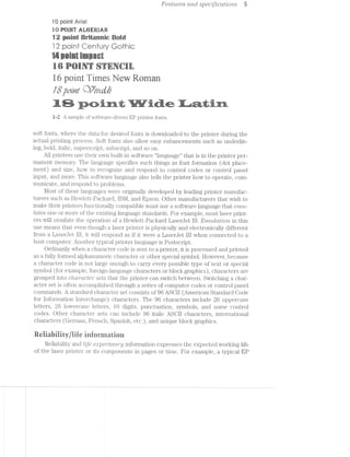
Laser printers (Fig. 1-1) have come a long way in the last few years. Not too long ago,
laser printers were expensive commodities restricted to the few serious businesses
that could afford them. However, the precision, speed, printing consistency, and im—
age quality offered by laser printers made them extremely attractive peripherals. As
computer designs continued to advance into the 1990s, laser printers also advanced
while printer prices plummeted. Today, laser printers are available for under $600
(US) and have become commonplace in homes and small businesses all over the
/2M ‘<
" '4/<;._.
- -V=:;i-.'=- 41"‘.'4§‘_ll§1_“{%Z;‘:’viivyfiv >141-2.‘/1us;-:i.;"i.2>R-PE~;>-.14:¢=sr£':-_;;-5'S%@:¥:1?‘?1$:":§£E‘;n-=>-=1-F-‘-1..-:1}?§:5:If%'E:EI15;i‘EI?E‘l17.*’ . . L ' '
, ‘»*»~~< . “ *"$*'~"*" “‘+ Liiii!-1‘‘:=i:~#¥1;1:1:1s:3:=£.i2?a=i¢&:i:i*i=3‘ '-¢:r?:;>1‘--,'::>=§>‘:G5lJ‘=a$1~=:§¢':$<<:e¥$w»¢E:§~§=:’15* -.5 .-;::>1;=»=:I1-1»=';:»1»:E:I=.=1-::> '~;>, "4 ' “~ /'_»_, ~ -, / Q.’ - ‘~;,:Z:;;{z‘;1.g2r::’5mu}lFs%%§§§};:';;-Q1;- ,.<-;:;:;,-’£.;:3.»:';3:13:-:=:=-Q2‘. $°Sa'r.~f$»//~ é~%¢~(¢¥~-(¢>~P >»/V ~ "” /7 ~' ‘ " ’ V’ 'rs v
<¢§0». _ - :' -’ . -.-v-r»: .~*'-:~--:=:--:-;-;---;»>»;:»<-=-:»;»;»:-:'---;-.=:»;-'--;-.-2:-:»:;-:---.1... 1:-»;.-:15 =:- »'I.-:15:214:5-':E.=:5:::1:£:I"-_=:§;:';"--:=,=;3.1"-311;;-5154;:-;‘=Q-$11-55{§§
-. '-: '<l'1~.'Iw.1':'lvin'<>’H.':¥£zZ"rI'. ~:_+:i.:~.::1~:-~:-;»- .<:=~~ :~'-.1 -Mes:-;'~>n:=a.“1%~‘?‘-».‘:<>1.¢1J:Is:i1€ ‘-‘-‘l>‘:=:=:~;=§ .;':1¥;1:':-:1='.1ii;1:=-I;-'=I=I$>?-->§§~>: '.§. ‘.:=".. “‘-:1*>.>AF' =:1;1":F;=:l:’-1*‘W111-11:-;-'I’ .?:/=--1%»v->FE111£1%f;1ErsE1--£1.>E11r'I!.=;P»:*%.1€'E-1:1‘5:"-¥:2=.'=.'>':'='-§.‘I:'¢1: ':
,-;-;;¢;~-i.:=;v-;.>.-,<-=.=.—=»~.->:-»>.a.' -- . .. i i . .< .
it-i<: -'-§:?.§7i‘~“1_'=£W:5§5??‘-(A!-*iL’@715'%$+."'-‘!'t:~"713331!<§§'§§5:-J?~‘$§1$131Z'§1$;Ei>}.5~§’§‘"§-'§>‘$‘*3:3. <‘s1$s<:~i~ »g--airs; "T.??¢:':I=':1:I:-9.=-15»s'j1?$?"£1£21215EI5i1iIZf;=EIiI:F;:35Ev.-.-=.-.i.i.i.».-,-.i.i.i.. ~" I ~ 1?? " i“W ' '“:_*" ”"' “$5
i = :».==:.;:~--».-_-_-.::»:»:»;-.-;;-;<»:».»:-;;;.»--: ;--.-~. V -.-:4-:-"5;:;;5;;;:;:;:;:;:;;-;»;.;:;;_:;:;;.;.;=,;=;.;.;;._.;.;._.;._.,.,,,,_;__ ,_
sr<e.'~2 - L11"""*3;Z=21:I:1?:I11:311'I1IJ;I:I‘=3111:?I:1:I:II5}:5:31:3:I:?:2Zl:1‘3i'-1:1. ..:1:I-1:‘-:1:-.. .‘:1;1:¢.I:':I:1;f.¢=1==>I'>I" I » »I~.5-<11»;1:,:=i-.,;;:I:;--.-:-:-;»:»:»=-::-: -i.is»:in:-:;;:»»»:-:-:-:.»:»:>a::;-;:;&21;:»=;=-.2:; =-2:»=. .,,__. , V ) .
4 .. Fl ' ~ .1 . ‘€~V 1, - .~ ~' v‘ -‘ - ' iii‘ ' ‘ “I“‘4»!}“ . “ A H _ WM ,,,, , it _,_, yr,’ <, ;, ,;,-/,t-~,~~a»<: , / »~ »w ..
’i'
,¢
,4 ’f*‘?.-s‘?>’
$0::;..<‘i'i,/,
. . i . . . , s >_». /~.-. L-‘-35 . --M /,.<» . ’»‘/'-¢'fl§‘S€3€~?"'I'I-‘-‘-1""I'I‘:.'Q(:"Z-‘-‘“VIII{.'I'.’§3§€‘.-§">§'i:;:1'."$:II-I-‘F3,
<1.»-.»$3:€Ei»‘<t~v:&~R~$Y:w:‘»i:§l:3:a-:5§?i:¢:%~:~:'~:1l7~:"-W-L—>'nil;'5¢‘i<?':%"i?i:1*$i§?€<5':R'lf§€$§:?‘§§?*Z?i?'3*¥*1@ ' '>i4.P}4.~‘-1?':¢:>9q:5‘§*:Q5='lk-‘l<$&i+>!tlziflttv;1!~"<<$‘?:E‘::§"'*1I?fltzi:??:%;=i£Fa=35?;bi_llZ*;$1:~3li‘~:?~£~>¢E=:%Ei§1¥§1i .-:-iiv‘!»:E'I:-:-‘$3:1.1:I'I51212511"?@513?-f@$Z'-§<Q$$$Q>~§x<‘K?‘Q’?€$§>J:?>5*§:':§l5§€¢3 . ‘:~2>;i‘_>.=1-'-W.» "‘ ».---':»;=s:€Ii%=.-;-;_::. :5.-1-:»:-.1gr»:;t,:,--,.»~ir;=;=1---s‘:-‘.1.--;;::r.=z?-.rrr.> rs‘
‘"/,"-*“=>‘*'i*»"i~‘-‘ -'~*~==.i-§s?~:?i-‘- V'f<‘»'.'.-"'.:Z-',-{.55;;5E=$$};=;==gE'5"3iZj:':I:'5":"E233$5.3%=;%1:":r;;;§_:j:;:";;?,:;i-I3.;.g-.15.g:€=-:i¢:;; - . -A..>.‘->;:2==5-iiia?<==1=€;ri¢§zgaura.:=>>t:=1ii2x<as_r==:.~~s=s§at>g{L<1a2:3sfires>v=>,:a@;-=5@ei££2i@sir' ~ '$%¢:}§;;:1:-I:>;:¢Er' .-=11;a€»:==.=;ss;=1;%=:1&§¢='=@E»;;e€-5:-{$11-=--Q "'*5‘¢»
1.>.:>.1i=,=-:z.='r¢=;§1=.~1inisi:-i2i1—w:;a=:.=~a:z»>;1;=s-=;=+s:»=‘=1/s==:ian-:»~:ir~sv-ee¢¢;'.::ins-1-..-;»:»a::=;;=>;»:.»=;-- " 1. r:.*.~.:-.~»r»2=;'.-as .-.>,.»<=~>. /’i:‘|w.‘.:II_'I"I.'-"'1 '1;--1+ -.»;:-;.i.-.:::¢,:;=-1.-1»i . 4)2-I-,'. - .. :'-;-:1 :
- 1 -_>:,,_,.,.,Q_,3wigWW€?,:,,,,,$_,.,,,,,_,,.,,.‘w,,,,i._,‘ ;_,_.,__..,._<‘ ,.. V , _ - -- - . _!."' -. . » _.x~,~,. M
K . ° , .
are
»iw‘z=§»"~ s
=3;5%
§j%
_<->“4’'.9
--,.vn» ..1-=2’0}”-*.~$98”$"
~'.-",v.».‘*/,it“)7”
/
~/u, .4’$¢"#-=
53>}.,.1,5
2
{V>3V
3,5/'
‘Q~/3".
-$5»
'/./~§»-"~
” />,/
‘v / ( ~
1,. .» 1» . ~ ~ I. ._,~ -_—* ~‘ ‘ ~ .. . . ..‘ . . 5... 1
i >8 ‘ . =»= ,1-‘ .< :2:”»;gs?.-;@4‘.:z;ir3»r:@;$§- ‘<6’ X-,‘*»;;3-<—-1-;>.‘~:~»_~;-:5»-<-;/.n-:»m:;;;pq;_.:-,;;:~;-<;:p:5-.c¢I-.&r;*:' »:1._.-t;~-‘:1-*9 =-:+-.= ;;:-1;-#7,»;--;;-r»;;".; . _ ,_.g;=;;-;;g':.-.g» w ;.-_:- -.»,~;::;,;.-,. ,- - ~ . _ ,
;zii;ii;;.=.:!:_i;;.:»::'5~.:':?3;?E..- ., " - 1 -' =”" -~15»---X - 0’ S; Q 7‘wt ’(‘:A ;¢x'<" “-a A 4*.-<-»...__.. » if--i.-“<0 x '4 " "'= '"" '~'_ , .. ., .. _ . ...-;/'--/I »_,.i~». .. ---.~»=-.,,-.-:2:-- "i-":-‘-.~~-~re.ii;==,..=__.._=;>».i.~.:=r;§:¢~-;=>gi_ 'arman;'===:,:g~jai;:ege5i:;>-=;i-:,;.;.,.,..:..;:.:---'--»r::»~>I~:=-.-.»= 1 = ~ .- L?‘ - ' r~"<' “‘1~ '>>''~"
w:§;<¢¢$‘==,t:a~.-_<;=~--set-w*e>q'*>a;»sw<%-§;55‘¥;$z . -f''~7»>;'-;$'-“:2L7‘-I-I»'-Q-I(if5NEQKi-I-:$03%~i-2lZ>Q_I-L-7i‘I~$i¢-t-L-1-PQIK-I-E-J-J-@=.'>.g.+1,,,,.-,.‘ ii .;- V ~ .,- _.v. 5‘. -. Q <1, ~ ,- .1=/-»Z{,~./ @-
» »:‘ K . 11*‘ ",-.'~~~r; - "~>v‘i ‘3>'s>n'<iiaje.,_ ‘"7: ;.2_';'.;;-;:,_ _ , _,~ - - '~ ,"‘;‘i~i-. ,1 ‘~.;'a;'~,,';:5<i»;,e:,:-ii»;._»_i_i. :~,:»,;=-‘=1;>:;.;:;;:;»q;;.,:¢i;;=,'=_:;v;51';;; ;;:»;».-~'~'~» V’ ,_ H-'~ -vi V >'~i 5- -- - ‘ ~,.",i;
;’i:~..~»:‘ . I/< r ”‘~ ‘vs ’°~§‘¢s~ k »*‘¢":~.< >~ ~. »_fi/ “:4 t ’. . ., _’- ‘ -" ’¥ ‘ '*~,
/Z?
.¢.,.s.». ;_<,~~»‘E=§,~.’‘~‘31‘r&‘<»,‘f*4i»‘§ '§“>}§/ ~. “¢'*~*~=< Yéjqé L‘ “* *>’t*‘,/‘ ' ~ I ~- i 0 fix W
‘ti, ~ .>, .. . ' v»=<~»i »~ / -»~
“'<e<~~"*¢~“~'*“~J ms» *~$’<““>‘:§‘/I ~-“}=“<‘*“’:){~7 5~”?'l, st.ii.’¥W’T3’5‘“"”‘”°*Aanm‘=1/'~ ‘s x ~<~ r L ~:s'$fs,’<."
s §§‘?""/;~='§’<sl~>“ §<l"~‘r€r'>">$*3*" '>l“"'~¢3-{'1 '7““"”’”""'¢§%$.»;;r,j ‘ ~" /1 =1 . e7 ‘F/-=*¢§§' " ‘7;‘$§§§’{ "~;':
‘~‘s}/1 “figs “=2 _j‘§,'~f 17?‘ It‘.-‘§*,~,"4‘s>;’§~*y§-%?;s;< ;.“,““,',.‘- __‘ , _ we ""~'/>-»>.r<a>,'a_,s,,.;¥1 »a.a,<, V '»’i'€<¢, ,5 1 " , W’:'<'e<>==
, »
3*
/‘K
5 . , ., ’- V N ma.
tr nag» » ~*-~iz~. <ns1,»<“i 1, 11 4 A~,- ..i"°s/‘if-‘it. ‘., *3, &~<,, /~ QA *~ .._TfJ._”_i»/.~__.».»,.,",,.~_(ant.e_?;n,...,:?>..>i»,>...?..::.:..,1......<arresis.;>~ Q6}: "’x¢+~§,;:*-z*<s/~.e;;..;;s~’*" _.,- em ‘~'. 9-鑧§(JvQ% < ~- 0% ;.ji3,',4I,>:}:j'.I'j~.-_i‘_~¢';!.~';_;?§<ir;':/‘i%fi{:1;?{Q1‘:13$3.5;1:§1*:3*§7z£$¢~;:E$;§:f.@ZTi;.i11:!:1§5:¢z§~®1:'%‘I>:3,.Qik;$";;;1:},tit;in:§:?j$"1-j:~1E¢i:§2IEitiE§*'_-153$?5:5&1%*;"5I.“'1éIEI1'i?1E -I-.‘.?'£s‘i~>i!;¢'-‘I=T"=‘-" ~»- " "A-iv/1:3‘-:1?‘ 4 "Y ‘ 2'5?» . ' , ‘- -¥3'}» "
- ~ ‘* ~ J.-re:-:':-~:-->:~51.’--‘-:1‘-.~;'c~:=RIc>:-W$:~§*=:-;~;~:~;»:./:e:>,~=-:a'.§>An:-:-ta-'¥-1-;:~:~‘-:/co:~>:<-+:-2;;-f»:<¢~:»=:»%:-;§a»,»~L/:#Q'its::~:';';<»:-::~<$§d:~=rfi-*1“ea»:<»:‘-"L--4.=§Z?’/:L ‘¢~»@;,$-45:»--Q5§>'{ -Q41; 3 / 63 §, ‘~ ~‘-;‘s¢ -_
sat? =~ ‘- ‘ -=:<:>~:r!s¢:~>*>-" ~ is a {S-945 Y -"H ‘ Vx - K9 -:-;=:~.~:‘<~..':=:-;'win 1r:»:~">,-: -‘~==*z-;/-»:~':=-2@“,=::i:x:~: -=;~=:»~~.: ¢~;*-.*‘I:~:i~ ,>.'~:=r:~!ai,--:->::<i-:-.';&:~s1-:>1w§~'>sn:»~2%-=<r:=s5§§=':1;2>Ii.=5-'~,<~-'-mi“$‘5>‘:~v~"'=-P21¢I-3-l'1;=§?:!=I;'=>:-2455;...<. 101;?‘/v “5§ 9" . ;§ 4' < -~,‘i{W-- 4 . ~ . 4.-1- '§§ sh , .‘.~-<i...~<..i,<i/. ,.,- )' .. “set, . . we-<¢— i xi/->¥¢~ a 1~' ~ -, ' , '"1:=9$§=:2=:?:;1:1.':‘=§$. ~:‘1:= -§:'<"‘-:.-.*-= >3;-' 1"-"":1’*%§£.&<*1:$:1:$ 5'.'Qi:§:§5£-?iSfi§€f._:l'$-;'."'~:1‘_1$;5.~:i‘.;.;E‘§$§%:1"5i:}:fQ_.f‘*¢g;"?§'§I1 ;;:?,_»_~:1;;&:;'-1.?-55;$Eix{¢==?j: ;. <1-;'_¢.>: ,:¢:’;’-;'-;;-'~1=1;I{->' :>>~ , . _ ‘ ‘qriy-_4""'i' A I“-I':., N
._ 3<-,‘x_é'~___,. t: . ¢~. '/<10 .1, , ‘ _~ ». / as ~~w i ' / ~ ‘> "’ , r" ;. 33- , xi‘ 52,, - ~-
‘ '§'I ~ w ‘ '6‘, i:’;.'-. 5;, Q. ,->1? vl ‘Q
H/(' .»:/ -A->~ '< <: g A.
7” (Q?a ~ ~ :
A
23’
YaW,’Zr v
ff“<1;,.’
’<’
/-2%,
~;?"'@if‘<~7»:at’
'r
Z
vQ»/.<
,4,'£a",17<.
,‘%
¢~.
"4-§_g_‘Y’-§}<':*r‘W
/'
1*’ .-49/’7%
*6’s»
~_
».¥~
(’
see
Z? /
/f,..
V is
N/,.,,, 5%,fi
V:4:¢~
.W-.
31.3;Qfiliiil
' Y:»_#
I!{'9'/_
’ <'_B*w/
J¢*,% ;‘§g
..,.,,_/
s»~25?Kr
~”ti-4
-,.-..---r .-.'>:-' =.< ~-A -‘<- ' '3>1:1.‘.'E-.“'i.‘3l~I:'-11711‘?-I‘93$?"m11€"fi=."-‘I:-:i:'i‘dirt-??.£5§1?i1i?“"'§1‘=’$5I{=25>i§$3§3}5:5:i:?:;§&$-'5fkéti ' - ,1 ,_ »3.'.*-‘
. ~ ~ . ~: . V.
'—$:.*§‘T*’"‘§=*‘3"'5"."" T*§‘"~‘. ' “-2 ' T'.“:'F? Il~:i‘:‘<?I"“¥:-.41“"/»'¥*I*‘1‘*-‘:~*Q. i:»,IT.l'.~, ‘I:¢;1?£:»:Z-"~f>?:=. 'rem?111$F1=-Ffl1%ii1Z2113123:‘i31%‘l?"=%:5:1:;i1*-:~:->. ' - ' ' -' 5 3
"tn '-‘.-é1='-,-<3‘ .' ' ::;!"::E:§:::E.::§§§:':::::‘;::ésj‘|::;':':it-7:Z'32.":§;::1:§E:§£:§fi>.:$E:%t§éZ13‘:§'§-:§‘:5§ii§§‘?:‘§éiF§??§i3;¢.;=.'-:-2~.';.'..“.-iii:":":‘El:'7'71$§3>T$53I3Y55171E5F5Qi1i'E3§il‘3€3§&Ei2i55i7:$?i‘§‘1'?I':>¥->‘-T€~:§EE§i3;7j3I3IF£;'I:31--i-1,».-i-K’ ‘- 4 ,~1~I;:>§;=»- ~--> _:l//-'9 ‘ eri4i,1.,5,I4‘i-.=I,;:~:;3€=I;s=:;~‘.;a:1;s;s%%~=@=-at:2.-"Ii3;:;;=,Ij;=&==§-i_;§;=-:t_'u$a “- :92
~=-<?i,; -- as §m W, . s3~,.£,.
‘Y ~s"‘K"‘-'=1:§‘et2%"7f*>‘~> ' -7"> ‘ » ’ ‘ A» S‘ ~-‘$24
- i,--‘$1-2-§'t>*“> it .~ " - Y - 0 As ’
- ‘ ~34‘ati§i‘}t¢*fr2;‘:";§=§i*ti1.l.=-Tk ~ i » wt I‘ ~* ~ ,<_- - ~":.»’ *‘ ~-'r~~‘'1‘.»,.~ , -»
~ ~ .< “¢"~~* (,~/‘,’,.,'-'/--i ./n is - ~.i.>,4~~,»~,,‘/ . ,>’/ %~ ' t.1 ' , A I ..~ _ ,1 xv _,~ ~ ,.‘_ _ ¢
Q} A V ‘ > J?‘ ‘,' ;.$.¢§( (C5;-_‘§>~ / MY 2 6,; .~,_ _ :) ~) §K:>.,_,‘§ Jggwi ix J _"‘};/._ 7‘ QQ
{$7 ti Q - ‘ '-‘~ M“ 1 *'"1 f "'~‘ //".' » ' ~ * iii» ~ w(¢@’ $ » ’>, _w3_ '} R A 1 '6//;/49> A .< L .< 1 ~ , ~ ~ I ~ / <,r>/" fi~ »_~ ~, , __ ., A _ . ,. =..~,.~,.=»..1 ,.- ,,.,,,.,_.,1=_.._;:.<i.;.-. --11;-1:.-:55"-;i-4;-_-:‘:I;‘".=;I;1é~=.-$13:-5:1’--‘Z1111;+*I->1’iz1EJ:5;1>‘I:1:"'E;i:1'15.=1I§I:?:l:‘»Z1:1.-.':I-Iii?21:33:?11+=.1-:<';.».5"-J§:?.5¢ , ;(¢ '
, ;»*‘$s *1‘ -- +1‘ - .= -4.’ ---=-:<-1. -- “*5 ‘* ‘Q1 *1 . :~<~
' '4 .. as . /. ,. 1». .. 1sr‘ . ~4, 44 Y4 4 _ ___,_.,.__- .1, . R-. .. > < . .. v~
§;$.a,;>§.<<e;;zo4>¢. 3 2~.”,> ,% ~s'9<§:;_§*'~;l"’§<‘<‘¢-‘F- ~‘-P‘-'-"~‘*45$-2‘:R&I¢1~1-31'.;:=-»-/ ..-:u;:~:¢-=-zsns-:e>::»<,i<P~m<~.‘- .7‘:i-.~.~.~ "<8 -~., H *§,<r,»*»§,~$‘ 13<,<-_';§2€_;.~
' '- ' " ~' ' ' ' w -= ‘5'§31~;"'<‘3*-:1‘P5111:-1I;I5".5E=-2'4F1313-3’-'s»I:I:=:1=1:==I~' - -;:= I
A £?§$1)‘@§“/“£§i?~.»»$}3~.i}‘A‘ Q ",5 "‘~=»===-<--5:;--.f.=--.'Y‘ _‘<’/ '~'~"~.2£::1.'151:1‘;~-;5;-141:;:;:::::-;=»;:i=::;:£.;z<1~:;.,A é~.”.“’@ “> ~>-‘4
"_ ._ .- ‘ <, . - ., . "Va-», .,~ <~‘fA~,,} ;:_;g$:;%*§*§<, gifig _ Q @+§> é
.4<=/?7‘- -<~v».".-"7“*- >' ‘~>:>~~.~ .. ’ Te» ,»,~<.~,*¥4$~§y.ere» .~.'*,'.»>~.,*,».<;a.~ in A
'~. =1 ye, - --. >1. z -<9 .> ‘<5 P-?§?%<* ~ ~>; '~~$'$$'-<>";~,;e-"’;r§I<**-
:_~~;~g;>s;s(,>,,~,<:, ‘§;‘r._-@}7ii-%§‘‘>'.'<4.3._$.~‘>.§$:-‘>‘,s~,,&»,<‘¢ X N . .., , . . ~°s<<-se-v=-.¢.=.- ‘v' ans ~~~=1->s-was-s-kéi-ss/45-/Z4 -sec:-le><r.§=$e1»1» “Xsins» ¢_ ."" »<<1.<y.~.-_---W-ii -is-,»,@‘~>, . ._..» raw»_a;,i;:t;,,s ;> ¢‘.’>~>="‘$'~$;" -air.-i. -ii ~' -'§,a$f'>'<z§<13--.-“ ;>, , 4% >-»~ -¢‘is;>r.' -' - ,-/iii-23%»‘ “Q as:<-:2?-<-=s<.~ we-~~n=§~;,»g~; ks;-<§3s ears. .i==;;=@:x=:=:=='==~;:time;:=sawnR4::n‘4"r§‘§2~wr¢>:a-:~;-». - .y~>$-¢.A , ..:‘<.‘<G'§$¢<‘? -its .3 , ,~~;>_./<>3¢,.,~@,~;5=_.;>_>*3;;»',3
V, 6' <>"‘~i'~’¢?=-ten,- »::;>i. -‘rs<~ -W--' 4*? -
» ..».~ "3z‘A < *-"e~'<< >*“s<>>-° ‘M *'/‘ ' -iii‘ T- 1'»,n‘4; r ./-=1-. »>':-. -‘> .- , _ ‘- . V - ' i _ _ w ' " -- :;.-:; .-.-.7. .v- .1: -;'~‘_'-' - » i -5»/... .- _:;._:,;. ', _. .... . .. . .. 9 x.‘ ____W?G_|_‘,_ X 5, W. A, , ,, __,. _,_.,.,,_.,,,,._,.;@,Q,1
¢ . ‘ '-
R ' e
/
5/
1* iii-..¢,.';F-*r‘,§,<-g - - Q; -°¥~f"_">‘*;'=*;- 1"-I / -t ,~>.<-~-~»~;<~
- st§it%>,;~ti$is~'"- " ”- ¢ ‘as’ =- I ¢ 9“ f ‘ ,, <:. ‘.7 _’.'>i.~,’~.,,', ="‘-€;;1¢;==:;:tg;gi~;,»E33,.-> -
rs, /wt)». 'v
Q~-.-.‘- -».- - ./I-.’-.1-I.-.‘-,.<.§~-K. ‘ - - . ~ , ---'-- ===-1'1-1'-'1-:-~:.‘ - ».- ». L ‘ » - "4-@213‘ ‘e?-fir-'1:-.:?-411 1?‘-:1"
"=-~ '=' ' - iisfig ' -- * . T - » '-~ . ~ 4.,-<1 . - - ‘ii ‘ - >~ '-»~= '- ~
<~ i=~ e -*1 = ‘“*" -" ‘* ’* » ’ ‘ ’ "»/ ‘ ' . ~ -' »’ 1 ~ '-: ‘ ~ ‘ .' iIr»1ti..a=_i1,Jt.'=;irTrifa-=ui:a.~-.i. .../<‘ » I ', » =.-"7*==.'i"?=‘.‘;."-."='.'-*3’1lY~‘£I
g~' , 1 3% ti‘ . ~ ’’ ’
§:,{‘
¢¢2
av» er/’
‘U
atv~;X’“ 35>;I
7458'-'7
3'
~4§'<;»’§,
/
<5‘-,
'1-'
2%‘
9, ti. ~ '7~ /r~§§,~>;.,-=-. - .e ’ ~ . ,1 Lfigpa My ::.= we <r'/t,m*)§=.-§,"#'-§“~e*2='1*»s-" we .. ; ~ .--¢"i:$=>.».P'~#>=>>:;1@s:@:=
.‘. ""‘ ’~=‘"5" ‘aw 4%g “.~,_gTg; -‘". .. es,-vs" r,- r -_ :*;<z,~$s¢:~<. ..-;->:~,-;>-.=-:-;-:$:.-Q9-atu->1;=-=->1-ing:=mn&>As>-/~. (~}?)‘1'/ - -*’, . :;2‘r'flér-1-'31}!-1241'Wl'rL,v‘-,9‘ —I,-‘Q5"'!h§lf.-=‘:1I‘y1"~_~ih$§*~-lkl, -1 _-F¢é'¥J'=Ji%‘-I;f'=EU3;=.n§“IQ-Z-1)‘)!-Ii—‘?})~ - -1 z --.> - A->,~. .»--,¢.-‘~.~>.;Q- _}»}- _pgNewweis/an-im-aver:-ir~-irqin.-:31>:2»:-2':_:/J:}_;_“=_._‘-::_}A:'fifl‘:J;_':".u1{*]I,lb}:4‘!'Iv;v2|§<:I:'}§&I',“ .~‘1}. '¢/,j#‘{vf{;‘fil!:v$§$H‘$v‘$'* - ~.- i rm;-..¢a<@i=-,-at-,;<,;r-4.?§$,,,< ~.4-==<@-are-ezaiai-stair»->~=-.-=s=<>5,52» *1» -- M-$1», . ‘~45 ».in~¢~<.<s ~ »i,4_.>,.i=§m>—.;.§>/.~,;.;.;i.3;.;.-1-er»e-i<s-:-=>;<-4 ~./ , est.-wit--.-i i~ . ‘A‘ii‘u§'|‘H'/n‘v‘~‘5'YL‘vQwfm‘r':"{'§T—"55'4'*>'§W}§?'§'~‘}f5'|"'§ 1'1‘-'-W». 1 .~< - ‘ea . .. ~'-:=- cw -,$*.&§,<.;m(~~.;»;»;;.-';:<-;=-gin-:;:-:—_-4. »_-.:¢;s_=;.;:-,_-;-=<1-;:-q=:i<;¢<t;-%~-::-:-<< §> *1 ‘~ ~.‘n;s;-:-gem;-;-;*»-:i.-:- l i..;.>:i.i:-,, vi ' yr-ii-.'-?iiIv‘.~1_Y.*‘e;1§!f“Ui;jfiggtfbwél§§§~.;§;Y*{i-¥;,?‘EE;~¢QlR‘J}r{Z}{1!jfi§:_ ~,, in - -7’-4 , ~ 7- i§:!~ >~~: -. ‘ ‘I1-<.<':’-'l["'R}fi,?:E:;::$11G':I!$}i'.:::§k|§{.j|':
577 '
:22=:=-22;s=;n=:§¢==;;==:(::@;sai¢<2={s;5saw’-. -“-<.~'<><$§’* £4 -_ ;.-F-_ -~75-"e=3>§%£§*2-stirs-atraisin=¢5<;;$1;1=.$:%=r£s;=argrmfiarrijte2s:s;=:=;¢;;$5:1;:§;;5¥:5
- '— " » . » ‘5""..>--;=»:.;==-.‘~:-‘~ "" I -"7
‘ ¢~;‘-,-v/‘Q. ~ e.J=,5 ‘~1L A<':r'$l- cw :.-, _ 1 , _ in , 'q<,i,zz‘ 1 ><'~,.<: .-, , ‘ * “I Y‘ ‘<1"1'~> x~-‘>.- - w~“~‘ ;;.*2i'-$": N »1‘.' (( - / * ’/m ~ -tints _ -Q cg , J , 2. / $y.,< ,?A Q, _Q; Kt ‘¥~§~ Sh , 4),: (Us >>-*§"m N A, ., 1.1M“ . H Y I ,1 I
, W < . > , xv _ H . . g
:=:=1-5:;-?=.:.::->1"? -. ,>-.;>-.%r-s1 ‘- --‘-"I'==. <"’-‘-‘ -::--.- .¢:::¢=1z1:';1' '-1..‘. W . ..;-;.».¢->.: “ A - .».~¥--- - -- :1 »-..-.»:--, - . ' < - 3: ‘ >21 (
- _r H — -:;=l:';>$_:;:¢==>."g<-s-.*/ ,1 >-itfi3E5i’1'i¢*¢‘=*i§I5E12355'I?»i‘=§“i", .- - » . _ " ' -‘ --Y I‘ 7
’:.i;=1.;;; . . . ; s;%;§i:...»I- ' - ._~_-.-;.'.,i»_¢-i.- f.;>i9',"4;'<-3'“K-§§”!i§>;5.g1,§=.§E':;'§:;j5§§j.3§;;i:§:jI-gr}:-.':fi " ’ ‘ ' ' ' --‘r - » ‘ »' - ', .
t:-5: ' ’» 3*-:=a>-‘;:.'§; .. '- ’ ' 1; :-:':’»"§'S:'.'>.»’5'-1.-'»’"£35175:$tI:7.7:11}i:?3§:§25§i{'4:P5I2EZ?:'"K-1?" ’ - w -- ».-....., 5:-egg-_;l;;:.:. / » _> 4;-»’'3 =.;_.q;._g_'.»:;.=-u‘.»"»~'-->:;------~:.<-2"‘ _ . glé - - _
-:5/-b
‘"2?
V,
<"$" -5Q1'5?‘
,5,
13?, .3
=--=1<:'¢-.~;=‘=:z' ....:'2-'1:-1;. . -" ' .. . . 2%»; . ' ' We ' ' ' ~ 3 ‘I 6 4. ’ I
..1i1;*-~~ -I.= 14% .4,» 1 » - ~ V 1$53:-§‘.2~X<:th.;;/'$»;: . <- -~~‘r""‘ »»?:Q?;i)§:1§1i$.’§filEE§ii'$- »- “ * , 1’ . R, , , . ,
.. .. . ' 1 . I ‘ ' '
arciC0.
84
- '--'--<-~-- -» - » '- . - .. -1.15» '1‘ ' .<<¢:-:1. '1 "1". , Q-, ,- :“'¢='/»<:*<'<-izmii; al‘ / a»;=--'> 1:.----9;-.»>==-1->'>~~:, - 4 - -- ~ . » _ . -- . .. -' ~ t <> I . . -- » .,-»g=~ ~_.§;t;.; ;;.--- - . . — *1:12; l / -,~V;¢;<_¢5-_.;._;;_}_;-§_¢_¢;5_~__/,, , i -¢.;,;~,s;<.;; -11>-;,.;;@ - ,,,,-.1. < - » ~- »
. . .i:-‘?.--I-.s-:1-:='»'.-PT?w--' » ‘“"'1-Eisién+:f=:2'2s<>i1.i;- 1"‘. - . . , . '~'*'»~ ' » §'*?2I$».f""' = ‘ 1“ * - '7 2 Til:
I ~ I ' .‘ i 1.1 i< i
» . ,,; ».».,-';;;~:-.:"-‘f-..-v , 1 .3“ .» I .
:-1-:1-11;-=-ii==:r:ss1_a:;=2a=’:2:;:zi§=ss=;. I =. _»_. L ' . - . . ' > - . .;.—_=; r »- . ." 3 ' ' /, » ~;-A 51-f :»¢ ~ . ,_
Hewe-Pack 1°81-:.-
'»';»-5*’?-.‘-"1,
vi.,, it
W
, ~'~ 7"?‘ Q ""'2'.’»§“ ~ l‘;/2?. ' J‘ ” ' "‘ °L i ‘~ ~ .~: /‘»~ ' -Z1"? {>1--‘.~I$~<:I=.‘.=¥'~*.‘<<.':'.~J / » > ‘.1=;£t1'~i€1;t1:‘.23*.-2';2.i§'i>€$i$I~£§i§2-355'.3?3f€1:':r*Zita.€=si5;‘€§{1.;l¢5¥‘.-11==~=Ii'=}¥2@:'E':'-4 ‘*1 /1 '.(‘,,,..~~= - $54»/< ix» Y‘/IQ -J 1‘ 7‘ ' A i‘ la . ~ ' 35;I."-.-::.;:éi¢'1;.-;2-111* of ’ -,1;:.':¢z::;=<..>';-:¢;<-;;jz1;::::;:>;::s2.'2:;:<;'1-;<<2::.:_-5=;::;';1:.-:;a1:: <>::;~_:::,.~:-..'>!-. X; -~~,,Y_,..~.-is ' ~"- an ,3 ' 5'" .- » 2;. ,. < '
'--<=<i"-~»=~»'1=~ 1 *~';1:~:I-I:»:>¢--':-.’:a:=.2-'1§;:<§:-1:191-=:='.=:1:z2’>.2=-=.=&i==1:11.-'51-1:1-;I>~u¥1.:E,i»-:t=.-t¥':'s-‘:-.=§~ -, . - ' '- '- ‘ ~."- .'~ 1- ' " P
""" =-‘l=1i‘.<.?1'I-'-‘i:'%?£i<=?'$i:‘%i' ' 1 " ' "<,;->==~—-*'~°“‘- r..--~"“ Q; 1:’ ..~.1 '~:~ _ ’ *
i ‘ ‘' i W ‘.>i;'~'<;£-1i:;'.1_-:'.~::1':<1'i$‘ ‘ .» ‘.‘< .‘<:>‘I:Q?-ii:==§§:'-$11132:2£.§';—?:=.¢i1-Ev;‘;€=-If¢l1>1'<'l$'Lre'=;;.;H x . 4* 7 at:~.:{x->:<i:.:-.-.<-:_-.' 2 4 vi-§l<<-.:IJPL-ix-.-."A41-§.'I'.i¥Z{->:§1_'1{;(~1-I-I5:zI->&-RLvI¢I"~/» "1 ~ ,;==;<==.--,1-..:-..:-_i:i.~.~:-'.=;...;: , ‘ar¢.,;>. ~ ~ ~ » 1 ~ ~ ~ - - -
ii
ii A Hewlett-Pacl<ard Lasenlet lll printer.
i](https://image.slidesharecdn.com/ozgdplurrtdj8c4ktjrb-signature-f36449d24fae8f28749ba408629a60e09bfd643da03035012a2b233e7710df3e-poli-180806114914/85/Easy-laser-printer-maintenance-and-repair-7-320.jpg)
![2 T/ize c?[8C7Z7i"'Op/‘2.i»OZOQ'i"CZ.QU/'Z»’ZlC? _];)'?""’Z1"lr'ZiZi6")"
world. This book shows you how modern laser printers work and explains how to
maintai.ii them effectively.
..-art verview
The intense competition between printer manufacturers has resulted in a stag-
gering variety of laser priiiter models—each with different sizes, shapes, and fea-
tures. ln spite of this physical diversity, every laser printer ever made performs the
same set of functions to 'f.l.'&l.l.SCl‘l.DO the output of a computer into some permanent
paper form. The process seems simple enough, right‘? in reality, however, it requires
a complex interacti.on of electncal, electronic, and mechanical parts all working to-
ether to make a practical laser printer. Stop for moment and consider some things
rat a laser printer must be capable of.
First, the laser printer can do nothing at all without a host computer to provide
data and control signals, so a conununication link must be established. To operate
with any computer system, the printer must be compatible with one or more standard
communication interfaces that have been developed. A printer must be able to use a
wide variety of paper types and thicknesses, which can include such things as en-
velopes and labels. it must be capable of printing a vast selection of type styles and
sizes, well. as gifaphics images, then mix those images together onto the same page.
The laser printer miist be fast. lt must communicate, process, and print infor-
riiation as quickly as possible. Laser printers must also be easy to use. Many features
and options are accessible with a few careful strokes of the control panel. Paper in-
put and output must be convenient. Expendable supplies such as toner should be
quick and easy to chaiige. Fiiilitll}/', laser printers must be reliable. They must produce
even and C.OlIl.SlSlI€1ill print over a long working life»-often more than 300,000 pages
(expendable items must be iI‘€plEtC€C;l more ;l’requently).
as-e*i.e
i it- -{*1 . -» 1 -- ..- T
'3 Er _ M .5 _ V -_ it @
You are pi'obably woiidering why people use the term eLccti"ophotogmpitic
_']3"7"’Zl’7"Z.Zi€7"‘ when talking about laser printers. ln truth, electrophotographic (or EP) is a
broad l1€lf'll1 that refers to a 131‘.ilj1il€1I‘ that functions using the electrophotographic
proces Laser" printers are electrophotographic printers that use a laser beam to
write image data, but there are also LED (light-emitting diode) page printers that
use a bar of mici*oscopic LEDs, instead of a laser beam, to write image data. Both
laser and LED printers are electrophotographic printers (although laser-type print»
ers more conunon). You can learn much more about the electrophotographic
process and see how laser and LED printers work in this book. In this book, the
terms EP];>rr"2Irrz.te1", l(Tt88"'l"])7"Z-"12.-t€'?"‘, and LED ];>r/2'/utc/2" are interchangeable.
U3
nQ51? nRifleatnr seeifieatis
Make it point to know your laser printer specifications and features before you
begin any repair. The specifications and features give you a good idea what the](https://image.slidesharecdn.com/ozgdplurrtdj8c4ktjrb-signature-f36449d24fae8f28749ba408629a60e09bfd643da03035012a2b233e7710df3e-poli-180806114914/85/Easy-laser-printer-maintenance-and-repair-8-320.jpg)
![4 The electrop/totog?/up/1'20 ]J7”Z7’?/Z6’?
connections require more interconnecting signal wires than an RS-232 cable, the
hardware required to handle parallel information is simpler.
[EEE 488, also known as GPIB (general-purpose interface bus), is an official
IEEE standard for parallel communication. It is not as widely used as Centronics or
RS-2-32, but GPIB supports network and bidirectional communication between in-
struments. The GPIB technique Was originally developed by Hewlett-Packard Goin-
pany, where it is still widely used in their line of printers and plotters.
Print capacity
Pi'"mt co;-pdc/tip is a generic term including several different laser printer specifi-
cations that outline what a printer can do. One of the most common print capacity
specifications is p7"’Z’7”?,l§ speed, which is measured in pages per minute (ppm). Inex-
pensive EP printers work at 4 ppm, but 8 to 10 ppm printers are available. Next, you
must be concerned with '1/'esoZ.ut'io"r"2., which is the number of individual dots that can
be placed per linear inch. Typical EP printers offer 300 >< 300 dpi (dots per inch) res-
olution (300 lines per inch at 300 dots per linear inch, or 90,000 dots per square inch).
A resolution this high is adequate for most business and personal graphics. The cur-
rent generation of laser and LED printers is capable of 600 >< 600 dpi resolution.
You might find a section on paper specrfijcdtions. Although dot matrix and ink
jet printers are very flexible in accepting a wide variety of paper thicknesses and fin-
ishes, the paper used in laser printers must fall within certain weights and finishes if
the EP process is to work correctly. In most cases, standard letter-size, Xerography-
grade paper (16-24 pound bond) will work. The paper also should have a plain fin-
ish. Shiny or gloss-finished papers will cause problems with the EP process. Most
laser printers will handle envelopes, transparencies, and labels. Before choosing
such materials, be certain that they are labeled as safe or tested with laser printers.
Poor-quality materials can jam and damage your printer.
Me’n'zio'r*p is another important specification for EP printers. Because laser print-
ers assemble images as full pages of individual bits, the more memory that is avail-
able, the larger and more complex an image can be printed. Typical laser printers
offer 512 K (kilobytes) to 1 l/lb (megabytes), but 2-8 Mb is required for full-page
graphic images that might be produced with software such as CorelDraw. l/lost laser
printers offer memory upgrade options.
Print ciiaracreristics
Print characteristics specify just how printer images will appear, how they will
be produced, or how characters from the printer will be interpreted. Fonts, software
emulation, and character sets are the three specifications that you should be most
familiar with.
Ajbrit is a style of type with certain visual characteristics that distinguish it from
other type styles. These characteristics might include differences in basic character
formation, accents, and decorative additions (that is, Courier versus Helvetica type).
Figure l-.2 is an example of several basic printer fonts. Early laser printers relied on
font cartridges that contained ROl/is (read-only memories) that held the image data
for each font. To change a font, you changed the cartridge. However, with the rise of
Microsoft Windows and improved memory systems, most current laser printers use](https://image.slidesharecdn.com/ozgdplurrtdj8c4ktjrb-signature-f36449d24fae8f28749ba408629a60e09bfd643da03035012a2b233e7710df3e-poli-180806114914/85/Easy-laser-printer-maintenance-and-repair-10-320.jpg)
![0 1'/re etecwop/ziotog/mp/tic pm/rite*i"
toner cartridge is rated for 200»-250 pages, and the image-formation “engine” is rated
for up to 300,000 pages. Many printers are rated at 5,000 pages per month (about
200 pages per workday). You might see this same information expressed as MTBF
(mean time between failures).
Envirenrnentai inferinatien
Environmental specifications indicate the physical operating ranges of your
printer. Stomge Z€’l%]3€7"CLf2L’l/'8 and opercutmg rempemtitre are the two most
common environmental conditions. A typical laser printer can be stored in tern-
peratures between -10 and 50°C, but can only be used from 10 to 82°C (on aver-
age). It is a good idea to let your printer stabilize at the ambient temperature and
humidity for several hours before operating it. Reldtipe /in/n/2.vjd'1lty can often be al-
lowed to range from 10 to 90% during storage, but must be limited to a range of
40 to 70% during operation. Keep in mind that humidity limits are given as non-
condensing values. NO7ZCO'7Z-(.i€’l”L5i’)'Z-Q means that you cannot allow water vapor to
condense into liquid form. Liquid water in the laser printer would certainly dam-
age its image-formation system.
Your printer also might specify physical shoclr or mLb'2"dttoi"2, limits to indicate
the amount of abuse the printer can sustain before damage can occur. Shock or vi-
bration is usually rated in units of Q-force. Keep in mind that laser printers are re-
markably delicate devices; any substantial shock or vibration might disturb the
optics that direct the laser beam. LED printers are a bit more rugged, but also use
optics that can be damaged or misaligned by rough handling.
Pliysicai inforinatien
Physical information about a printer includes such routine data as the printer
height, width, depth, and weight. ln some cases, an operating noise level specifica-
tion is included to indicate just how loud the printer will be during operation and
standby. Noise specifications are usually given in dBA (A-weighted decibels).
icalasseies
No matter how diverse or unique EP printers might appear from one model to
another, their differences are primarily cosmetic. lt is true that each printer might
use different individual components, but every laser printer must perform a very
similar set of actions. As a result, most laser printers can be broken down into a se-
ries of typical sections, or functional areas as shown in Fig. 1-3. Before you trou-
bleshoot a printer, you must understand the purpose of each area.
The ac pewer suppiy
An ac power supply is usually a simple electronic module that provides en-
ergy for the fusing assembly heaters and erase lamp assembly. There is typically
little that goes wrong with the ac supply unless a serious fault in the fuser or erase
assemblies damages the supply. You can learn about power supply operation and
repair in chapter 6.](https://image.slidesharecdn.com/ozgdplurrtdj8c4ktjrb-signature-f36449d24fae8f28749ba408629a60e09bfd643da03035012a2b233e7710df3e-poli-180806114914/85/Easy-laser-printer-maintenance-and-repair-12-320.jpg)
![b '1 '/"L63 etectiop/totogiup/2;zc ];)’)“"’Z'7"Z~Z§€7"
uses a set of two rollers in compression, where the top roller is heated to melt the
toner. A paper‘ exit sensor detects the passage of paper through the printer, and the
thermistor sensor is used to regulate temperature in the heated fusing roller. Chap-
ters £5 and '7 present more detailed information about the fusing assembly.
Erase lamp assembly
The image that appears on a printed page has been transferred there as a latent
image written to a special photosensitive drum. Each time the drum rotates, the la-
tent image must be erased before a new image is written. The erase lamps clear the
drum thoroughly and allow the photosensitive surface to accept a new image. Erase
lamp failure is usually easy to spot as you can see in chapter 7.
lllain motor
EP printers rely on substantial mechanical activity. Paper must be drawn from a
supply tray, fed to the image formation system, fixed, then fed to the output tray. The
mechanical force needed to support all of these activities is provided by a single mo-
tor and mechanical drive assembly. Chapter 8 describes mechanical systems in detail.
Writing rneebariism
The data that makes up an image must be transferred (or “written”) to the pho-
tosensitive drum. As you can see in chapter 5, this transfer is achieved by directing
light across the drum surface. For a laser printer, writing is accomplished by scans
ning a laser beam across a drum. For an LED printer, the light generated by individ-
ual microscopic LEDs (one LED for every dot) transfers image data to the drum.
Writing is controlled by the main logic assembly (or ECP).
Scanner»-inotor assembly
When a laser is used as a writing mechanism, the beam must be scanned back
and forth across the drum surface. This scanning process uses a hexagonal mirror
that is rotated with a motor. Note that scanners are not needed for LED printers be~
cause there is no beam to scan across the drum. You can find more information on
scanner assemblies in chapter 8.
Papeneontrol assembly
Paper must be grabbed from the paper tray, registered with the latent image,
passed through the image foi‘niationl§ybten1, fused, and passed out of the printer. Al-
though the main motor turns constantly, not all portions of the paper handling sys-
tem can be in motion at all times. The paper control assembly provides the sensors
that detect the presence of paper in the paper tray, the presence of paper in the
manual feed slot, and the sensitivity of each EP cartridge for optimum printing. in
addition to sensors, the papencontrol assembly provides the paper pickup and reg»
istration roller clutches that grab and register the page during printing. Chapter 8
discusses the paper-handling assembly in detail.](https://image.slidesharecdn.com/ozgdplurrtdj8c4ktjrb-signature-f36449d24fae8f28749ba408629a60e09bfd643da03035012a2b233e7710df3e-poli-180806114914/85/Easy-laser-printer-maintenance-and-repair-14-320.jpg)


![aw-1 i-Q T1Zj]3’Z»C?CLl1 CO'l"7’LpO7‘?,€7‘ZilfS
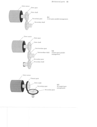
Not only can gears transfer force, they also can alter speed and amount of force
that is applied at the secondary shaft. Figure 2-4 shows the effects of simple gear ra-
tios. Gecrr ?"CtlL~’ZO8 are usually expressed as the ratio of the size of the primary gear to
that of the secondary gear (or of the number of gear teeth on the primary to that of
the secondary). For a Zirigli ratio, the primary gear is larger than the secondary gear.
As a result, the secondary gear will turn faster, but with less force. (For mechanical
parts that rotate, the force in the rotating parts is known as torqrue). The effect is
just the opposite for a low ratio. A small primary gear will turn a larger secondary
slower, but with more force. Finally, an equal ratio causes a primary and secondary
gear to turn at the same speed and force.
_‘m"‘~ ~ ~ ~'~ I |T‘-Ir
_.v‘. .’,'/"»'.'.'.'v'.'. -"2--_
. a .'.-‘I-.>'1-.‘-I>‘--.'4‘u “-17-I'T'I'~.
-- ' .-An:.j.:.j.:.:.:.:.:.:.j.:.::;.
......_.. ..-_ .-"<...........-...‘|-»_
...i, ‘H-»--¢.w_
In‘,','_' '_'_','_'_'_'_'_'_'_‘_'_'_'_'_‘_‘,'_‘_'_'_'(‘ :‘_"_'_'_'_'_‘_'_'_'_'_ 1"_ '_'_‘_'_'_‘_'_'_'_'_'_',‘_'_‘_'_‘,";
lL'>'-'. '¢'¢'v‘iA.'.v__»’-_.'.'.'_'.'~'.'.'.'.'.'.'~l .'-_-_.'.'-'.'.'.'.'.__ ‘I. . . . . . . I . . . - - . . . a . . .l.
-'-'-'-'. - - . . -‘J.'.‘.‘i'>’.‘.'.‘.'.'.‘.‘.‘.‘.'.'.'.'.'.'. ' . ‘ ‘ ' '.‘.'.‘.‘.‘.'.'.'.'.‘.‘.‘.‘.'.'.‘.'.'.‘.'.'.'.'.'.'L...-~----~-----»v>....i.». 5 " "" I l I
‘K
J".'.‘.‘.'.'.'.‘.‘.'.'.‘.'-‘-'-'.'.", |J.‘-'-‘-'.'.‘.'.‘.'.‘-'-'-3'.‘-'-‘.‘-'-'-‘.'.'.|‘,_._.‘._._.'._.'._._._-_-‘-_-_-_-_.|. -‘._-_-_-_-'._._._,,,_._._._._.|._.‘.___._._._._._.
5 5 8gens riiiiii§§§i§§§i§i§i§§§§iE§E;1"?iii*§l?*§‘i'§:§5§%§i§iii?§?§?§?ii§3i¥§::,1 ts:;:2:s:1:z:zi%as§:z:2:z:z:z:§;;.l '¢%;5z5;§z553232?;i§%1£Z‘??%ffi‘§':z5£552?532252523251
i;;E1_Z;E' ' ';Z;E;Z;1;E;E;E;E;E;E;Z;E;E;E;E;E;E;' ' ' ' ' ' 5;; ~-:.£.;_E;E;E;E;E;E§E;£;§§E;E;E;E;§:;;l-’ ‘-E,-E;E;E;E;E55;§;E;E;E;§;E;E;E;E;E;E;E;E;E;E;§-,2-'l‘. .. . . ._:‘:_:|:_:_:_:_:’:_:|:‘. . . . -._:J._._._.‘._.‘.'._._._._,." ‘q . . - . , , 1 » . . . . . - , . ~ - . | - ,'
... . . . . . . . .. 1' =.=;-:-:-:-:4-:~:-:-:-:-:-:-:~:-:-:-:-:-:;-1
‘u Z-I~I~I-I'1~I~I-I-I~Z-I '"-."~:-:-:-:-:-:-:-:-:~:-:-:~:-:-L»*"
.‘.'.'.‘.'.‘.‘.‘.'.'.‘. .-ufiiiliiiiiliiiiiIlliiiiliiiiiiiifliffr. "—‘_Z ' ‘ ' '_‘—"
. . . Y . . . . . . . . . . . . - .r -..".""~.......|.............,...... _--h'hhh-
-.‘.‘.'.'.'.'.‘.'.'.‘.'.‘_‘.‘.'.'.' f‘ I11311132111111!Iiliilliiiiliiiililiif 4-1"‘...ZI12Z1ZZZZZ31.'.“".r.
"‘-‘ ‘-‘-‘.‘.'.'.'.'.'.‘.‘ '._"' 1illiiiiiiliififiiiiiiiliiliiiiiifiliiiiii A ..-Ifli12III2I22IZ2ZZZ2ZZZiIIIT7_
d-_,_ - . . . . . - .1» .......-..................... _..|......H.......................»_
..v€‘!‘?f‘9f'.'i-_ -:'::::::::::::::::::::::::::::¢::::::::‘:~.
n..." 111211:§I1:ZZIZZ1ZIZ:II:II§1Z I‘;
I111 IIZIZII§ZIIZZZZ1IZZZIIZ1Il1Z. III‘.
B-In niuwvblnvvvulltcitiiivvlllllt uni
.-..
" ::::::::::::::::::::::::::::: “>
J.-ftitittti:!::1::::::?1-.L I1“... ......::::::::::::::::::::::::::::: ...-..I!-k
..:t$:::::::::::::::t::::::.» .:::::: ::::::::::::::::::::::::::::::::::: ::::::::_
JillIIIIZZZllillfiiliiiiiiiiiilh, EZZIIIII PZZZIIIIIHIZZZZIZIZIIliliiiiiiiiii :::::::::5 tn.“ "nu.|.n..."--...»-..||-4 --"I
£11172!1111121223!22331521222225} 251212ii......ZiI2I2Zl2£22ZIli:I22Z1I121222221122“-i.liiiiliiii ‘$151322IZZZZIIZIHI53111112325313:Iiliifiilillf
-45555555Eiiiiiiiiii§§§§§§§§§§§§§§§§§?- 22:17:::::::::::":::::t:::::t:"":::::'::":":""::::'::'::": 3:31““:=“:::":::“=:::=:=::“::::::“"=:::::
-==============.~, gi;;;;;;§22212;2;;;§;;§;l};;;I'1I.i.iII'I;;;;;;;;;;;§;;;;;;;;;;;;;;;i; fzaszzsziaaasass;azzsizzaieisszzsaaiaaasaaazzzzaaig
‘=="""*‘=“--i‘=‘I‘I‘EE=:-.'EEEEE5EEE=EE= -ZEEEEEEEEEEEESZEEZEEEEEEEE‘-:=E5?§E5E5E5E5i=--'EEHEEEEEEEEEEEEEEEEESEEEZ: 555555555!EEE535EEEZ"=5E3?E55?=55E==5E"EEEEEEEEEEEEEEEEEEEE:
Secondary .. .;,;.;;.;,;i;.;._.~ :::::::::::::::::::::f:f:§:§:1.'§:§:§:1'§:§:::::::::::::::::::::
I1 1222112211Uiliiiillliiilil. "5-?-I-Z'i'1<' JZZZZIIIIIZZZZZZZI2HIIIII? ‘““""""‘""“"“""“" “""""““““““"
6
gears 5555555EEEEEEEEEEEEEEEEEEEEEEEmiEEEEEEEEEEEEEEEEEEEEEEEE552355 'i,§35555555?515555?555555==---1============¢===========
» EgiéiiiiiiiiiiiEEEEEEEEEEEEEEEEEEEEEEEEEE55E"""555S5EEEEiEiii}? aaszs sisszazsaazsazszszsaaaazaaassszzaaazasii
""IJ_LLiii1€!3fi_1-I" ‘H21! lZZIIIZZZZZIIZIZZIHiiliiiiiiiiiiil 112221? 32212212:23222212122223:{HZ:llllZZZ_Z*"
'_"" ‘$31 1ZiiiiiiiilifllliiiHiiilliiiiiiili Sill?‘ 'Z!iZII;Zi32122222322211!11122212227-‘
"‘......ltiiiiiiiiiiitittiHIH21:2I:t:2Z£!....."'Y "£12111!11111211131123?!!I3ILL""
=1=sss2zszzassaassassszsss==ezsae2:==sss===z2= ~=1===============s===‘-F’
‘vsisszsas2222222222222222222222222222?’ ““~------"'
*--nggzsszsszsszassazssegizwr—¢u'-------u.|.-P
High ratio Low ratio Equal ratio
2-4 An example of gear ratios.
Fuiieys
Pulley assemblies are common in many laser printers. Like gears, they are used
to transfer force from one point to another. Instead of direct contact, however, pul-
leys are joined by a CIZ'7""Z'/U6 Z/miactge, which is usually a belt, wire, or chain. The action
is much the same as the fan belt in your automobile or the drive chain on your bicy-
cle. A basic pulley set is shown in Fig. 2-5. A motor turns a drive pulley that is con-
Drive pulley
---‘fl1'---------- ""‘ “ i i Hy: r>_f‘|:,=rs~,i:v<= .........rrn_
_;-$55: : ‘-*'~‘*‘”""‘-""“‘“ ‘ L ‘= ’ * “- -A-7’ ::::;_:.'.v-M-M.:.I_;::::?n
...2.-1 1:11:27‘ 222152] $111322
.mm._1_m“__.._.;::::...1 ::::f:mmmE::::
. . .. "'...i.~i.»-ms--I?i”‘
:1.<i.~ s-,;-ii; -‘<t'i'~~‘:"‘.'-!'il=‘':!- - -' - -' -' ~-»-_=z.»".i.'<;-1i>.r..~mi-==.ia@-1..-.'===i<w.~‘.. i..-4 ,'-.:-.=:i~~i-i ',":A‘ :1 i-we-..>= 4' _ ./.i.~'-.w:'=i.~i.-*~~: .-,1‘~1z.$l.id-7-tin‘ i‘ .-.2;--=:*.,.@,{.;,;,,m.,.;<W.ii-.i-m,<i,l;,i,.&t5,.i,u~i . . . . _. . ‘§‘‘$‘5“I"'<'*‘i~‘‘HI-w$"‘ vi...->.<
-'_.-‘_.-’_.-‘_.>'_~~’, .-".-".-".-".-".-‘
-‘.-‘.-'.-‘.-' . -,.».< 1"" 1'-"-‘-"_-'--'r..i=
7t3r1.)§~'ii.'T.-‘>"7."';~$~'w.‘>21! - -' ~- -' =~+:-ii E‘@'<v==1‘$~ii:i:*‘i*‘-t-iismiireeiA J_ X‘, . ,. ; )8 l t (‘
. -1.1.» .-,.=,=,-». -‘l‘,+wJ,‘I-‘q.’-¢[',:) ,‘.‘5-N5w.:~»:.;=i.», l'=.‘-'.“:‘;i‘;‘,*.l‘.¢.:“Z?"r‘~.~‘.'.', :=:»>i- ‘is;¥:;'?;i’
' " '--:-:-:-:;. Fl~';=‘.1i!‘.i='1‘-I.'*i'~I‘~l*.‘-=.‘I-"3'%~%ft~£?*§i?‘13'~§"a‘t~t5 Ehi55'>‘3liF%i‘I§{lif51;iQ¥" -:;>,:»~
;:;:-:~:-:-:~:-, ~-wt r=3;-‘.r.<=2:- ' - -:='-“>-:-'
|-.<I:¢:¢:i.,>§.kI.=.-.~_,-_3.3.5.3».-._-.g.1.;:-3.-4;». 5_._._-_._ ‘~“‘“=‘¢':‘.J';=~;~1;}§}:1§E,LEjeflfi";jEfJ.§f.§'i$4'L'~£3131“’" -.-.g.g._.~.-.1._ 5.3.1.
:§:1:1:?:71<:§:1:1:~3:$:fi-:7:=$:1:$:¥:»:¥:1:1:-:-:~:-.-:;.- .<.;.;.;.;.~._.;.¢.;.-..;:¢:;:-.-11:53:15:§:$:!.'§‘-E§:1:1:§E'$:§:§$:§$fi¥:§:E
'1i1‘¢§?=1§=:51E1§1i¢?‘¢'=§=513535€¢§1’1§=i1‘=E=§$‘=51E=fi§$=:I:"=:€¢'1$545515?=3'=‘=:1i5?i5<.‘=ii¢:=*315¢$:=‘¢$5¥*~:1€1"¥*:"‘i~*'1?'.D1 _ , -:1:§;;$-:-:-:9:->:~:-£3:-:-$:~:;:~::-Q-:-ii:-1-:»:7:-:-:-:-:-$:-:3‘>:-:lE-:-:~:-:»:-:~$_:5:»5:-:~5:»:€:»:-:?>:-t-:-:1:-:-15:-:i:;$fi~§1:$:-:1:-
tll T Q I i:-:-:-2:121:12!:1:1'1:1:21:1:!:¢:¢:4§;1:t;:I¢$:!:2=:k!§:1:121:-'¢:1:I:i:1:!:¥~¢:1:1:5:‘<-:§:!:1:1:5:?:¢t¢:§F:1$:=:=:1:f:i:E;F:1:1:-:?:1§$:3§:F:3:1:=
‘~— 1- ' 7:¥:5:1$1!:L¢:5$'$:5.'¢:=:1:"=:!:¥:-:§:¥:-:31:-:*9'1:36:!:5:7*$:5:$;l:1:¢:3§1:5:3:Z~.'-:%i'.5:7:i:¥:5:¥:7:5‘t¥;5:4:-:5'~.3:1:5$'5:1.-$'».1:*E¢:¥1 IJ.‘.*>.'.'.'-'-'/~'.’~'.'-'-E‘>'-xi‘?>"'-'.¢'$‘-'1'{~‘:'|'|::‘.')-(IR:-"'»'|‘|'-‘¢ 1'|)‘w'-‘v‘I(-ffb'|Q>'-'¢':‘>'J"gB_',}j):’|’-‘:'-'<:
-::-2-: .~:<-=-:-:-:-:;:-:-:~:;:~:-:;,-.;:-.':;:+:-:5~.-:-::;:-.‘:-:;; :-‘-:-.»:~.~:;:<=:-:~:<~:;.~:~:;:~:~:-/.-;_.-'».~:':-:-:-:-:<. ' .».-.-2:;-:¢:¢»
3:1:1:3:>.1:1;¢:1:?:15>:¥:!:=:-:1:1:-:1:-11:1"-12$:-<:=:51:-:1:1:1:-rikii'1:R:1:-:i:1:!:¢:21:-11:1:-z1<1'1'¢:=:-5§i:¢:i:*1:>"-:1:1:1:1:1'1:<5:5:=:1:
1:1$:1:1'¢11:?:1:=:F:i¢:1$:?:1$:1:=§2;$:1$$:55:?:=§:1:'§}:i:l$:RF:€i:$:I:5:1:¢:=:1$:i:$$:1$§$5:1:i:=:_>}:i§1*i3':=:l:i:§:I:$:i:I:I'¢:¢‘3:11;:§:§§:§:§:§fi:i:§:§:1:f:1 ::§'-:!:».I:§'I~i>j!§:I:1:1$§.;:~:§:1:§:5§Z:tI:izithgI:3:75:5'22?2&5!-¢§§:I:i'5t5:-:2???1:16-:1:-:55:7:23?’ 17-"J v$_,<__§.;_ fix. .’... $_:~..;.. . ;. .7_.. .,;. .;._.’ ..._,. ..,.
NV
> 5- :
.. ... . . --. _<,..§,..,,r.. - .. ..--- J. . IIOI .~...,... ._..-_..,.~. ....
-1»?-!~Z-I-1-1-1-. .-I-Z '.*1~.'I~.~1'I 11"‘-.-‘-1-.-.03141'?~.7'§'I1.'1~.>fIC'1PI'I~Z~_~I~ -I~§.C'.vI~III*f~f» 51" 1- .-'2.~I~.€1I~ ~I-Z~.~'I*"651
121:1:1:15:12?‘52355:!$:3:?:3:=:l:1E1:E3:3:1:=$'1:1'!:!:1:kI:5<:>:i'?<:i:1":¢:i‘1:$:1'i$1:=:P.-.-$:1'§*1:1:I'?'1'1:1:1'!51:2‘-311219121:~.;.;.~.-.;.-.-:;~.-.-.;;.-.-.-.-.;~.;.-.».4».».~.~>.»>.-.-.'.?:-_-.-g:-.-+‘¢.-_~*.;.».;.<;._.-.;.;§.;.;-.-:;.;:-.-.c-:¢-,,~:§~:~.-.-.;.~;.-.~».
:-,-.-:-zi.-:-:».-'-'-'~:~.-i~:~:~"-:-.->'».-:~:-:-:~;-:-:-:-:-§:-:~>.-:->'-:~.-“-'--:-:-:».-:-.»:-.--:-.-.~:-.-.-:~>¢.-:->:-:-:-'-.-:-.->'-:-:¢.~:-.-:+:-5:5;:;:;:;q:;:;:§:§t5:;:;:~:;:-$:;:;g:!:;§:;:;:»:;:-:~:->:i.;:~q:;:;:;$:1:~:§§:-:;:-i;g:-Q:;:§>:-:;>:-:->:~:-:;g:;>:-:;:§,‘-:r.§:-:§:-.;;:¢:;:io-'
i.~u.-J.v.~.-.-.~.'1'.~.C-.'l~b.'.-.€>.-.v<+.-C-!'Z<~?¢:,;.-,.-.;.-.-.-. -:'.-§.-./.-.-,-.;:-i~.<;;-it-:-:53 -¢>-.-z-
~1*;:!$:;I:I{:I:>$:1:¥1:5:523:13?13:31:33¢:1:¥:5:1:33:-:1:!:7:-:?§§:Y:Z$'?:Tx?21:15::{:=:1:-:1:~$$:-:~.!?~‘:-§:~é$:-:1:~:?:=:1:1?§'~:Y:§:;:F
- . E-:1:-$:z'¢1::1:=$:2:1:=:7:-Q1.-:1:?<'-'2-:-:1:l:I:?:1:?5:i:=:I:1:i:i*1:-:1:1:1:$-'t1:?:1:I:1‘7'1:i:-;I:1:>':&>l:i:l:I:E<;1:i:I:I:I'1:1:;¢'I:5¢t>¢<:lB it - t . ., -1 ., _ -:~:->:;3>:~.-:-;—>.~;-;;:-$:;5;:-2:§1*.t-:1:1:-:-:-:~:$-:~:-:~;;:-:-§<->1;::;;@-$.21:-g:-:-1-:_§E-:-fl§;:5-:->.;;;-:~;-:1;¢:-.-§;-:5§:€--
Q Q 7 € :;:;:1:;._:;§:;:;:;::;:;:_.;:-:;. ;:_-:-1:3:-1-:5-:;=:;.-:;~:5;.;:-:_ ;'~:-:;.;:-. .- -' 55;: ;:-:~:.-1-1;: - -:-';:;:-.;:_' -1.;
1 -' H1O O1 OI (- 1 1 1-Zr-=-rs-I-as-=s<-13¢?-1~=¥=~2#=5:i=§=;ri=§=;s=&as?Ea=s‘F$3>M=§=E=§=5'==-==$,;5fi$§§52==£¢-$§1ia<~a-:-:-.;:-r-.-:;:- .-.~,w.w>:;:--.1:-:~:4».-N.-,.-.b¢-> ,:_4~.-.-.-2-.-,;:»'»:¢>,.-.~>.
1:?:1:-:1$:1>:5§§5:1:!:?:5:k1':=:~:1:=:i:>:?:-:¢:=:7-¢-1:1~:5:1:I:I:-fitI:1:I:i<:-:Ii¢-I:1:I:I'=:i:I'?'1$:¢:i:<:I:¢<'1:-$"3:=$:>5:1'-:§:=:?;2¥:>2¥:~)1-52-1-Z-I-2-_~I-'-5'2-2&3-E2-I-1»:16-I-Z4-56%-5?:-2-2+:-I-1-:1I/-5:Q~2~3-:5!-t~'~!3‘-2-2553!-'-:-'-t-:-45‘-'-"t-‘o‘5'-'i'- -'-r-'2'-I*-'
--.-.'.'.'.r.' ":1: -4 i‘-.-.1.-.'.*.~.*.~ '.- - *.'.-.'.~.~.~.-.-.~.~.~.'.+.~.'_' -.-..~ '2‘.-;.'.-.-:)-'I~.'.0.-"2~C- "-.-Z"-;<;I'2I‘~1-‘<1-1-‘
g"-2'5:1:1:231:1:'cI?I{:€1:=:¥:Z$$:i:i§$:1iI_;'1:;‘;i:1£5:1:I:1:§§¢-i:33:1:l$2$;k1§I$§ritlzititk?:3:§:?:k3Z1:%¢?1§1at=_9$;'-:=$§~'?';;?'>‘ '-‘r-'-‘H-'-'-'4'-'1'-‘rs U‘!-Y In o'| .'.'(.'~'r.'.'- 7'). r.'fi'.'. (Ag. -'.'.;..'.'.'.'.', .'.' '.':§.'.'.'.,“- QPIQ“ '»
"1,’ ‘ ‘>'¢'» '<'~'-'¢'-'¢'-‘>‘-'~'>‘~'-3‘ '.' '- I '¢'.‘>'v‘-‘f ‘.'.'-'-H . -'-‘A .‘»'.'.'.‘- .'.'-'.¢.' I-2‘. .'-' .'I J"-,§...>._,......_.,.....».»-3'..r....._...a...._................-..........-3;.
'*‘ "-">1:1:15:12-:-:=:1:1:¢:1'1:1:21"1:1:1:I:1:1:4‘-$:l:>:1:1"1>:1F'¥'='1F:?$$:='=:=t1:1:=:=:='=:35?"
"=;2r<:=-is£21=$#=rs===r%=1=a;‘2E:=z==$rE>k¢z-g=fe=:»:+'-4*-»**....,,,,..... ., .,,,,i..-,--
2-5 Top view of a basic pulley set.](https://image.slidesharecdn.com/ozgdplurrtdj8c4ktjrb-signature-f36449d24fae8f28749ba408629a60e09bfd643da03035012a2b233e7710df3e-poli-180806114914/85/Easy-laser-printer-maintenance-and-repair-18-320.jpg)
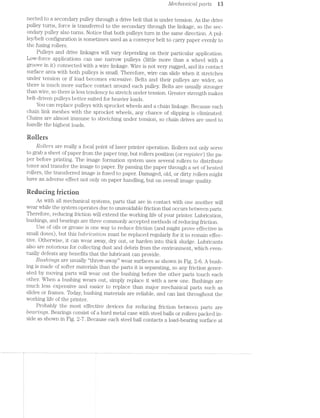
![M Typical CO77?,]9O7’L€’l’Z-15$
Roller
Frame /
Shaft .@
A bushing assembly.
/ -Bushing
F1‘alng ROll€l‘
'-'*-+:-- g .7 ..
-1-*r'—*'-"Ws:»'~"' '-'-='#a>: '=1<-‘*1-" "W-Y-'-1.,Shaft ~~-~ _. __. ;._v n . -4:3. -:;"g.~:- ~ ‘$3, :_ ~f 7_v. .= _ .-.', . :~ - .v .-» _.'1_.;~_,.»'}£ __ 4->.-~.¢.. $c;I.¢».'{:,‘~>
'|' 3.?» -~-=.i.=r..';.~ . ~"_ -" Y . 1’: -. » ' 1-‘3-.- -' ‘- » -.- - ‘ - ~ -.--' ‘ . :-.- ' 9., aw:-.‘ ._ -:' IN ~, 1-i-.=_~;1,'.;-.-J : ,/;'.}~_ 4 ,_- H ‘KER . ‘ .~_'l';:$§')‘:~ <. gfi , fi,‘_-,
‘]:;:;:;:;:;:;:;:;:;:;;; J‘ -. ;;:;:;1;;l1 .i _ 2“-7. __ .._._._._. --.-._ - -. A D __. ,,_ -, - . -; _ . -. .... H.-
/:/ .1;
' ‘ -‘YL“»‘;‘1§'i:='~:l-l‘ v 3 ‘ i ‘ '-. - ~ .‘* . **- :- ' .»‘*¢ 2*‘. -I1" -/' $51-“€':5l‘:‘*L"*“1‘ ' 51$:-,%Y"' ' "‘- ' ' ‘-. .- '~' ‘ 12». '- l“ ‘:"" ..--2 2?‘ w "‘-W-.
l '4‘ "‘~<.>=='»>- ’*> M - . . 2 '. - -- _ ,.>$$§"‘ '-:9 ,-<~" ~>.,- .' .-[ii -.1
J’ for * .13: ‘ ”%~»-5?" ll" -~ "R -
ea
-*-»&""'<§.~.....£v-V M?‘ l’ % A 3% *’§“$¢~ “f. . -‘
“‘ A beal lug assembly‘
Ball bearings
Case
only one point, friction (and Wear) is substantially lower than for bushings. Unfortu-
nately, bearing assemblies are often much more expensive than bushings, so bear-
ings are used only to handle heavy loads, or in places that Would be too difficult to
change bushings. Most laser printers avoid the expense of bearings in favor of inex-
pensive bushings.
lectrecaicalcets
Electromechcm"iccil co'mpo’2'tents are a particular class of devices that convert
electrical energy into mechanical force or rotation. Relays, solenoids, and motors are
three common electromechanical components that you should understand. Each of
these important devices relies on the principles of electromagnetism.
Electromagnetisrn
Whenever electrical current passes through a conductor, a magnetic field is gen-
erated around the circumference of that conductor as shown in Fig. 2-8. Such a mag-
netic field can exert a physical force O11p67"’l’l’L8CLbl8 materials (any materials that can
be magnetized). The strength of a magnetic field around a conductor is proportional
Magnetic
force
fines
Metal Direction of
conductor — - X1 fl’ "H" T F’ current
l ___._.__l """""""%* I
11i;%.I ‘I1%;<11,gr::jj___%_j_i iilgj :1j_%_:1 <I__%_,I' $1.-. 1...: _ ... n-an
2-8 The magnetic field formed around a conductor.](https://image.slidesharecdn.com/ozgdplurrtdj8c4ktjrb-signature-f36449d24fae8f28749ba408629a60e09bfd643da03035012a2b233e7710df3e-poli-180806114914/85/Easy-laser-printer-maintenance-and-repair-20-320.jpg)
![EZGCWO’l*"l'Zi6?C?/'l»Ct’7’Z'tCCtZ» CO’l’l’Z];)O’l*‘2/671ZS i5
to the amount of current flowing through it. Higher amounts of current result in
stronger magnetic fields, and vice versa.
Unfortunately, it is virtually impossible to pass enough currentthrough atypical
wire to produce a magnetic field that is strong enough to do any useful work. The
magnetic field must somehow be concenitiated, usually by cro'tlrmg the wire as shown
in Fig. 2-9. When arranged in this way, the coil takes on magnetic poles just like a
permanent magnet. Notice how the direction of magnetic itlux always points to the
‘rt-O'7‘tlt pole of the coil. if the direction of current flow were reversed, the magnetic
poles of the coil also would be reversed.
Coil , l/jlagnetic force field
/___...._~---- -- ---.~........._%_
__..--~-“"“::---~;Z§:m_ ~- at --------~ --- MTWMIIQW-*-»-:““'"""~
l |" 1:” ~. -. .' , ._ . _ V.-. 1, i - — __.' " I
'=.___ '-____ -~ _,"@"‘=i W _ Ar T T“i-.r1“M_’f§-W" “__~/-_“‘ '
"-... ‘—-»-.... i ?< I-i £3 ' ’ 3'” w _,_,----—" -—
""'-_ '""‘--- _- L - l . 2 I i . 2 < s . ___, ----""'* __,_—'-'
'“_-‘--___ i “M” 4 i 5 ' 5 -an _._- ' ‘ ""~' ___--'~"'""'_
< —- ~ 1 r ; = V 3 , , .._ __---~
N a—i__w—_,_““_t_- -I ii 11 :1‘ V 5 "I" W ii .’ — ,,_____M____"_m___m
__-»-——" . - '- ""---M-“ "|:.~ I:-—‘ ‘ma 2"-.-._‘___ ~-‘S . ___ .1-.u.._’ _ ~‘W ‘ I 31, ___‘,' ‘I H l V,“ I _‘--,:_ 1 “I
. .__“ _,_r_N_ M ___
... "—._._ ___; _ “‘i-i-—..._._..... i_...,.~....._..._.._...,i---*""“—-—"""‘ -
'-_..____ __:=-“*—__._ “Q *_,_m_
_...i____ -——-——--ia——--—————-—~'“'"""'"""-"-——--_ __--__._ fig W... _ —
21-=9 The concentra.tion of magnetic force in a coil.
To concentrate magnetic forces even furtheif, a permeable core material can be
inserted into the coil center as in Fig. 2-10. Ty_3ica.lfly, iron, steel., and cobalt are con-
sidered the classical core materials, but iron-ceranuc blends are used as well. Coils
of wire such as these form the foundation of all electromechanical cleviceU2
lvlagnetic
G011 force
lines
area.-_i _ —7_
___-_" ___.-> _ ___
~>' --' "
!~‘.’1’=£"-2‘
. ._ -...:_: .__
' 7 " —' ¢..».;;.~.. ‘—-4» -'-____ _ . —'.-__ -w_
_.- __- 1 ———._..__ "'.._ -_
_..' _-." ___ _ ._ :-~;.;_. i a... ___ '*-_ -.._
.' -' -»‘“' _ Y ~~...‘-..- "' ' 'n .- .- .._. j
I E__ -:__ .5: . ,_, -V . ~ - A fmfis F-., _"':;- '11 '1: '3
'"--.u_"'-__ _; , _,_ J "t ..._j*g » "i »-—"‘"___-"' C0111"-3
”'"'"—-“II —~ 2 i if F -t it ‘T_:.---""_ 1'-—"“"_ -. .- --, 1-*._..._. ;, ii . ii _____*- , i11ate1ia..
N _i___ —~ W . it it -~--~_ _,_ s
_.---"“"___- ""11"" *1-~ ~ ~ t" '= "-~Tl-"ix: ___ '"'-—-~._-"H -"__ -"'-Q“ -- P‘-'=='-‘=2 .. L‘-., ‘I’ ___—-T 7. ;i7_V___ *__ T , Q";-' _ -—— _"""':_?a""-<_ -"1.
. 1 '-' ll‘ I ..._ '3'“'"1 . Z»;-'1.‘~..~',.x<~..,__,___»-» _ 'w“_"'__':| _:I 3|
flLzl~ $_%
a
l |‘ I, .-'“":'um' -.L ,_ __ -=,_ .9
._ -___ --_,_ ""' _,»r.___“ ..______ .....,____ I ,.. I -- T
aaaa
'*'*—.... _.==-vi ' ' WK-,_ I
Z2.-id Concentrating magnetic force with a permeable core.
Reiays
A relay is simply a mechanical switch that is actuated with the electromagnetic
force generated by an energized coil. A diagram of typical relay is shown in Fig.
2-ll. The switch (or coittctct set) can be normally open (NO) or normally closed
(NC) while the coil is de~energi:z.ed. When activated, the magnetic field of the coil
causes normally open contacts to close, or normally closed contacts to open. Con-](https://image.slidesharecdn.com/ozgdplurrtdj8c4ktjrb-signature-f36449d24fae8f28749ba408629a60e09bfd643da03035012a2b233e7710df3e-poli-180806114914/85/Easy-laser-printer-maintenance-and-repair-21-320.jpg)
![Electrom.ec/trim/tcctl componems i7
Meters
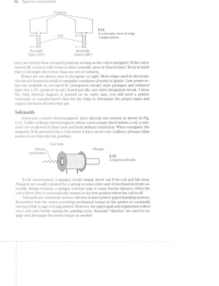
./l/[otors are an essential part of every laser printer manufactured today. Motors
operate the entire mechanical transport system. Chapter 8 presents a detailed dis-
cussion of mechanical systems and service. For now, concentrate on the motor itself.
All motors convert electrical energy into rotating mechanical force (torque). ln
turn, that force can be distributed with mechanical parts to turn a roller or move a
belt. An "t"7’tCZ"L(.iCZ’Z-O71 motor provides torque through a series of powerful electromag-
nets (coils) around a permanent magnet core as shown in Fig. 2-13. The core
(known as a rotor) is little more than a shaft that is free to rotate as its poles en-
counter electromagnetic forces. Each coil (also called a phase or p/tctse 2.u“mct2Trtg) is
built into the motor stationary frame (or stcttor).
Motor housing
/ Motor shaft
4'“1** >2“r
- . - - - . ~ - ~ 4 - . 0 1 v - » - . - ~ . p - - . . - -- q - , v | 1 - . --‘- -'-.'-'-'-'.‘-'.'-'-’-',' ‘v'1'-'|’.'»'-'-‘~"‘.'-'-L‘-" I ‘IT
1|-1:1:.;.:.'11.:.'..{.;.;.:.;.;.:.~.'.;-'.;.'.'."'.'.'.'i'.' '4.‘J.:.;.1.‘.-.1.an‘.-'-'.'.'.'.'..'3.'.'.'.-.'_'.:.'{$1~.-».'.-.'.I.'.1.~_'.'.- '11-ii’I , , . .4-P '
_r|l'_-‘|:1_| ¢_|‘v:.'-_-1-_|_-_-_»_._¢_|:-1‘_-1-_':-fafa:-:~:v:|:11::|_.:4-,-_-'-Q:-1.:-Q|1;:-:-1.:-:-1.:-:1:|1,:-ffI-:5-:.'{.:-Q|:1:|:|‘-'.:-H-jf»' Q ' - ~ - - | - ‘§' -
1. In'~_|_1_4:v_1_u_u‘~_-.-'1,-'~_-.|_u‘-_¢‘4'o‘-5"-_u_u_u_u_|_|_>,v'-_v‘|'u_-‘Q.|_>_|_n‘r_¢_n_u_v_¢_q'u_-I. |_-3.‘:|:|_>_-_-_e_-_-_v_-_r_w:v:1_|_¢_- -If n 4 4 u u 1 | ~ 0 4 J‘__¢
_.jI§Z;I:1}:11;:;I;kZ;Z;Z;Z;l;I;Z;Z1I31:31l;I;i;Z;IEZ;Z{Z;i;I;Z;IjI;I;Z;I;I;:;I;I{I11'!;1;I;:j';Z;ZfI;'I;Z;:;;"-'1'-"Z11;$1:1:13:11;Z;I;I;I;Z;:-I" '~Z . ' - ' . " '. '. - ' < ' ~ ' - '- ' . 1"
.-:->:-:~:-1-:~:~:-:-:-:-:-'-:-:-:-:-:-:+:-:-:—:-:-:-:':':-:~:~:-:-:-:-:-:-:-:-x-:-:1'-:-:~:-:-:-:-:-:-:c-' " ~:-:-:-:-:-'-:i:-:-:-:-:-:-:-" ' ' '. '.
.~:-:-:-:-:-:-:-:-:-:-sq:-:-22-:-1;:-:-:~:-:-:-:c-:-:-:-:-:-:-:~:-:-:g-:-:-:+:-:-:-:-:§;<:c-:-:-:-:-:-:-:-:1‘ -:-:-:-:-:-:‘-%-:-:-:~:->-:- - - - - - - - - - - '_.1.1.3.1.;-1.1.3.1.:-;§.,._.5;::-3.» ¢.'.'.'.‘-'.~.-.','.~.-.~.* -z ' - ' ' ' ~- ' -.' ' ' ' ' ' ~ ' ‘|'-I‘ ' 1.3.;-;¢.§;.§_¢.;.;.§.; _ ' _ - ,- _ - _ - _ - _- '- ~ - ~ _ - - _- _ ~ _~ _ v _ - _ _-
.;-;-;.;-;-1-'.'.:.;.;.;.;.:.'.:.;,;._.;. .~.~.:.;.'.;.:...}:.:.-.;._ . . - . . . . ._1>:,._.~_.;:,~,.,_. '. . . . - . _.:.
.421:1:?:21:1§1§I:1:°:?$E:$5:1:1:!:=:3 ==$:1:I:<:¢:I:1:I:¥*“ -' ‘F._:;:;:;;;:;:;:;:;:;*~';:;:;.;.-:;:;' ' -;-:-:-:-$:-:-:-:-:-'-:-:-' '* .' -' ' - - - - -'f-_--.-_-_-_»_._Z'1,-_-._,'_-_ k 1' A ‘-5":-'J'|'1‘-‘-'|"'-‘¢' -1d-'. . . -Q" ." 7%.‘.-V. .'.'.f‘f . ,
M » N -;;:;:;:;‘??;i P€rn1ELl1(-BITE magnet
A " ~ :?:1:I:1:i€';..11::?‘;:L, ;:1I;1§1§1§1Er_: . .. . .- ~ x A ,5 ,+» 1, l—,..- -:.;;.,;;.,;_..;.;.;.-l‘ poles (1 otoi)rununa--I~' ' ' ' ' ' ' '1‘ 0' Fr:-'~;-:-;-1-3 '-;->1 - --.-.-.-.-.-.-.;.- ~ - - - .' .- .- .-;, .-x III .. '.-.'.-.'-".< .~ - ~ - ‘ - . -' - .--' - ~(25.3!;.;.;.;.;-;.;i;§‘Z_-_-_._,_._._-_.j. I;.;,.',;.;.;2;.-Z;.- . _-_-_-_-_ _.-'_.-_.-_.- z _ _ , _ _ _ _ .
I-C1!-1-Z-I->3-Z-..-.-I-I-Z-‘-C-I-2-I»!-Z 'w'~1-'-'>'-‘-'3'-' ' - - - ~ - -' ' ' ’ -' ' ' ' Eli“ - - -Ax-.~.-.'-‘-'.'_'.'.--'.'>€'.'.-.~.'.*. 'I'.'I~'-""2-'-' - I v 1 -' -' - ~ ~
-:-3:-:+:-:-:-:~:-'-'-'~:-:-:-:-:-:-:-:..... -‘—'-:-:>.<:I:-'1'! ' - - ' ' - - ' - ~;.;..;.;.;.;:;:;:;.;.;ig--;:;:;;;.;:;-3:145-;.;.;. '> a ;2;l;.;.;.;.;.;I;I; . . . . . . .-'_ -'_. . - - - -
:==sEaraas==i====ia=2:-=:=2:zi:2 2 Er5>I=E1E==1‘==$= -' -. - _- 1 ‘I.I-I‘I:I‘l‘II-0')‘I-1-1:I‘l‘I‘I,q‘D'I‘l:I‘l.I‘l.l‘l_l'I'v:| V -1,-_“_v:1f|:w:u v ‘ D ' I ' D ' _ - -' _.' _-' _~' _- l ' ' ‘ _' . ' _ ' -
inn_._._._,--_,-|.--_"_‘._._-|-nu. -...--Hr . - - - - J
:a:~:1:Q._-_|_u)11-n:r:|:a:Q-_|:q‘|}_|_¢:|:u):o:|:n;n’$ if :-1-:-:o:u:n:p:¢'|: ‘ _ ' I ' ‘ ' .‘ u n’ -0' Q. _n' ‘p_ '~ I4‘ I 0' ‘l' 3 ¢,w‘_§;_'5 ' I ‘ _ ‘ ‘ “
;.;.;.;.;.'-;-;.;.;.;.g.;.-'.-»;.-;.;,;.;.;.~.;.;.;.-.3. v .~.-.-.;.;.;.;.;Z;._ . . . . . .-la .-'.- —4-- '5 - .- _,l;.‘,.,~ . . .'. .
-:-:-:-:-11'-:+:-:~:-:-:$:?:-'1:-:-:-:-:-:t-'-'-t?:-:- J‘ .». W‘ / ~:!.'!:Q-:-:-:-:-:-:- -‘l 'I-'- ' ' - ' '.;.;.5;.;i}:;.34.1.;.;.;.;.g.;2;.;.;.;;;.;.;-;2$;5-5; ‘w a 2 ‘C ;.g.;.;;-:5-.~.;.3{;, . . . . . ..-fr‘ .;.* .+:I;'<‘i.'.'.‘.'. .
.'.'.-.~.'..'.'-~.-.1-"A.-.w.-.1-'-'. -'.'.'.'<‘> .'.'. _'.'.'.Z '3'-'..'. .1 ' ' ' ' "'1 =75‘-*‘ ~ ' ' ' ~- _|_.-_._._._,- _._-_._._._,_-._-_._._._.".. _-._-..; _-_._._._._ - . . . . .r ' ,..==;~ . J-
'~'§-:-21:-:-:-:;E;:;?':-:-:-:-:-:-a-:~:-:~:-: __ ~ :1:-:15:-E-:~:-:-:-:-: 4 Ea N - '1' '“
P", -"'2, ."a.*"“ ' ."',.+'l"' e
'._ TIj3IIC/3
__ _____ ,_______ _ _,* . . -__._._.,..,._. . . . . . ., . . L . . 1
‘@:;=,=;>j=;=;;=;;t=;=3=;=;r;;=, * ~ , “’ =;=jr;=;:;t=;=g;;1-,,;.;.;_;.;.;:-,_j-. .;.;.;I-.;.;,%i
‘P-i=5523E;5;E;E;t5;Eg§tE§§;I,. . . ....3 -‘-'-'-'---'- A r.---v.'. -~-J‘
' Vvi]-1
Ml (stator)
3111
";.1;:fi;Z
I_I;IjI;-
1'33:
..-¢;.;.
".:~:~:-' _.~:!:j-:5:
*’Ifijljl
5:21;}
'55:3: -a;.;.;.
1.3:’f7:-:-
"~Z-2'1
3+;-r _._._.4.1.;
I521:1:
<_.,.,.
.-..;.;..;.-
25525.I04;-;-:1
eI-I-2' a-as--2+13-#32
.;.-.-.-_.;.;.-:-:-:;::1:-':-:.;.;.;.1*!-1-I
'~.1.-1;.
i-.-K
L'I;l;I;I
331':
.N.;.;.;
.1E1515! ..;.-.;
111.11
.*-.1515" .,r-
-'- .- ...
..-- iA-I.U.
Alv-
-.. .1I~'.'.
2»-i3 Simplified view of a typical induction motor.
By powering each phase in its proper order, the rotor can be made to turn with
some amount of force. The amount of angular force generated by a motor is known
as torque. lnduction motors generally require two ac signals separated by a 90 de-
gree phase difference. These sinusoidal driving signals vary the strength of each
phase evenly to create smooth rotation. lnduction motors are rarely used in today’s
commercial printers because they do not lend themselves to the precise positioning
requirements of most printers. lnstead, a close cousin of the induction motor is used,
and the motor is called a ctc servo motor.
The dc servos are powered by bipolar dc signals rather than by sinusoidal ac.
Like the induction motor, a dc servo is turned by bipolar driver signals in rapid suc-
cession. Although dc servos are not very precise for positioning, they can hold a con-
stant speed very accurately. This characteristic makes dc servos ideal for driving the
scanner mirrors in laser printers that must rotate at a precise rate.
A popular variation of the dc servo motor is called a SZ§€].’)j_lJ’Z7’tQ motor. Physically,
a stepping motor (or stepper) is very similar to a dc servo, but the rotor/stator
arrangement is much more intricate. Like dc servos, stepper motors are driven by a
series of square wave pulses separated by a phase difference. The sudden shift in
drive signals coupled with the intricate mechanical arrangement causes the rotor to
jump (or step) in certain angular increments, not a smooth, continuous rotation.
Once the rotor has reached its next step, it will hold its position as long as driver sig-](https://image.slidesharecdn.com/ozgdplurrtdj8c4ktjrb-signature-f36449d24fae8f28749ba408629a60e09bfd643da03035012a2b233e7710df3e-poli-180806114914/85/Easy-laser-printer-maintenance-and-repair-23-320.jpg)
![LU 1 LL}/p‘L(jLLL (jU'1'I’Z/_[J()‘/L(3‘)‘£-Li-S
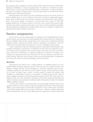
Adjustable resistors, lrnown pote'2'z.t'io'metors or ’i"r'?,€OS'l§CL'L'S, are usually used in
laser printers to adjust contrast by varying the level of high voltage. A typical poten-
tiometer consists of a movable metal wiper resting on a layer of resistive film. Al-
though the total resistance of the film, end-to-end, will remain unchanged, resistance
between either end and the wiper blade will vary as the wiper is moved. There are two
typical types of adjustable resistor: knob-type, where the wiper is turned clockwise or
counterclockwise using a rotating metal shaft, or slide-type, where the wiper is
moved back and forth in a straight line.
ln addition to value and tolerance, resistors also are rated by their power-handling
capacity. Power is normally measured in watts (W) and depends on the amount of cur-
rent (I) and voltage (V) applied to the resistor as given by Ohms law (P : I >< V]. Re-
sistors are typically mamifactured in %@, %, %, ‘A, 1, 2, and 5 W sizes to handle a wide
variety of power conditions. Size is directly related to power dissipation ability, so larger
resistors usually can handle more power than a smaller resistor of the same value.
As long as power dissipation is below its rating, a resistor should hold its resis-
tance value and perform indefinitely. However, when a resistor is forced to exceed its
power rating, it cannot shed heat fast enough to maintain a stable temperature. Ulti-
mately, the resistor will overheat and burn out. in all cases, a burned-out resistor
forms an open circuit. A faulty resistor might appear slightly discolored, or it might
appear burned and cracked. lt really depends on the severity and duration of its
overheating. Extreme overheating can burn a printed circuit board, and possibly
damage the printed copper traces.
Failures among potentiometers usually take the form of intermittent connec-
tions between the wiper blade and resistive film. Remember that film slowly wears
away as the wiper moves back and forth across it. Over time, enough film can wear
away that the wiper cannot make good contact at certain points. The poor contact
can cause all types of erratic or intermittent operation. With EP printers, it is rarely
necessary to contimially adjust printing contrast once optimum levels are found, so
it is unlikely for adjustable resistors to wear out in laser printers, but dust and debris
might collect and cause intermittent operation when adjustment is needed. Try
cleaning an intermittent potentionieter with a high-quality electronic contact
cleaner. Replace any intermitt.ent potentiometers or rheostats.
Reading resistors
Every resistor is marked. with its proper value. l/larking allows resistors to be
identified on sight and compared versus schematics or part layout drawings. Now that
you know what resistors look like, you shou.ld know how to identify their value with-
out having to rely on test equipment. There are three ways to mark a resistor: explicit
marking, color coding, and numerical marking. lt is important to decipher all three
types of marks because many circuits use resistors with a mix of marking schemes.
Explicit marking is just as the name implies--the actual value of the part is writ-
ten right on the part. Large, ceranu'c power resistors often use explicit marking. Their
long, rectangular bodies are usually large enough to hold clearly printed characters.
Color coding has long been a popular marking scheme for carbon-film resistors
that are simply too small to hold explicit markings. The twelve colors used in color
I](https://image.slidesharecdn.com/ozgdplurrtdj8c4ktjrb-signature-f36449d24fae8f28749ba408629a60e09bfd643da03035012a2b233e7710df3e-poli-180806114914/85/Easy-laser-printer-maintenance-and-repair-26-320.jpg)
![Passive components 21
coding are shown in Table 2-1. The first ten colors (black through white) are used as
no.1/ue and 'multtpZte'r' colors. Silver and gold colors serve as tolercmce indicators.
Table 2.-1. The standard resistor color code
€e1or lst Band 2nd Band Multiplier Tolerance
Black 0 0 1
Brown 1 1 1 0
Red 100
Orange 1,000
Yellow 10,000
Green 100,000
Blue 1,000,000
Violet 10,000,000
Gray 100,000,000
White --—
(None) 1 20%
Silver 1-. 10%
Gold 1 5%
<LDO3"'103C3“l>-l>C»0L'J QQOOQC'3U‘!|-l>~OJ>L'J
The color code approach uses a series of colored bands as shown in Fig. 2-16.
Band number 1 is always located closest to the end of the resistor. Bands one and
two are the value bands, and band three is the multiplier. A forth band (if present)
will be silver or gold to indicate the resistor tolerance. On rare occasions, you might
encounter a fifth band that indicates the reliability of a resistor (and is used only for
military- and aerospace-grade resistors).
Value band 1
Value band 2
Multiplier band 2--16
/ Resistor color-coding scheme.
i -
: .~
As an example of color coding, suppose the resistor of Fig. 2-16 offered a color
sequence of brown, black, and red. Note from Table 2-1 that brownzl, blacl<=0, and
red:l00 (because the red band occupies the multiplier position). The sequence
would be read as [band 1]{band 2] >< [band 3] or 1 0 >< 100, or 1,000 Q; (1 l<Q). lf the
first three color bands of a resistor read red, red, orange, the resistor would be read
as 2 2 >< 1,000, or 22,000 £2 (22 l<Q), and so on.
When a forth band is found, it shows the resistor tolerance. A gold band repre-
sents an excellent tolerance of i5% of rated value. A silver band represents a fair tol-
erance of 110%, and no tolerance band indicates a poor tolerance of 120%. When a
faulty resistor must be replaced, it should be replaced with a resistor of equal or
smaller tolerance whenever possible.
if-K-1'H¢v'MinQXQX $Gfl'e~"’{"4'!>"€"](https://image.slidesharecdn.com/ozgdplurrtdj8c4ktjrb-signature-f36449d24fae8f28749ba408629a60e09bfd643da03035012a2b233e7710df3e-poli-180806114914/85/Easy-laser-printer-maintenance-and-repair-27-320.jpg)
![22 Ti/pzlcctl CO’7’1Z]JO7*Z€?77,Z1S
Color-coded resistors are rapidly being replaced by surface-iiiount (SM) resis-
tors. SM resistors are far too small for clear color coding. lnstead, a three-digit nu-
merical code is used (even though you might need a small magnifyiiig glass to see it).
Each digit corresponds to the first three bands of the color code shown in Fig.
2-16. The first two numbers are 'oo.lru.c digits, &1’l(ll1l1€l1l1l1‘Cl11ll1lll)€t1‘1S11110’l7’t7,tlli’Zlj3t7;€?"’.
The multiplier digit indicates how many places to the 7/12./‘(J//iii; that the values decimal
place must be shifted. For the example of 2-17, a numerical code of 102 denotes
a value of 10 with 2 zeros added on to make the number 1,000 (1 l<t?.). A inarlring of
331 is read as 830 Q, and so on.
Metal
leads
/
. We
. . . ' ‘ '2 P : : ‘1 1).
Resistive material 10 A 100 Q ALMS) }1’%OU“
on ceramic substrate " ‘“‘
2-17 Surface-mount resistor inarkings.
fiapaeitors
Capacitors are simply energy-storage devices. They store energy in the forin of
an electrical charge. By themselves, capacitors have little practical use, but the ca-
pacitor principle has important applications when combined with. other components
in filters, resonant or timiiig circuits, and power supplies. Capacitance is measured
inj‘cz.rrctcts (F). ln actual practice, a farad is a very large amount of capacitance, so
most normal capacitors measure in the microfarad (uF or millionths of a farad) and
picofarad (pF or inillionths of millioiuih of a farad) range.
In principle, av capacitor is little more than two conductive plates separated by an
insulator (called a £1/Z€t€Ct'1"”ZC) as shown i.n Fig. 2-18. The amount of capacitance pro-
vided by this type of assembly depends on the area of each plate, their distance apart,
and the dielectric material that separates thern. Even larger values of capacitance can
be created by rolling up a plate/dielectric assembly and housing it in a cylinder.
When voltage is applied to a capacitor, electrons will flow into it until it is fully
charged. At that point, current stops flowing (even though voltage might still be
applied), and voltage across the capacitor will equal its applied voltage. lf applied
voltage is removed, the capacitor will tend to retain the charge of electrons de-
posited on its plates. Just how long it can do this depends on the specific materi-
als used to construct the capacitor, as well as its overall size. lnternal resistance
through the dielectric material will eventually bleed off any charge. For the pur-
poses of this book, all you really need to remember is that capacitors are built to
store electrical charge.](https://image.slidesharecdn.com/ozgdplurrtdj8c4ktjrb-signature-f36449d24fae8f28749ba408629a60e09bfd643da03035012a2b233e7710df3e-poli-180806114914/85/Easy-laser-printer-maintenance-and-repair-28-320.jpg)
![.Pctss/toe CO?'l?.];707"t€7'2$S 23
P1818 Plate
Dielectric
, ,_ _ Epoxy 1
Eisiiiigi-ikgzzii,-5 i
:: gap. ' _:§:;_. ,-
”..aaaaaaaa»___ . .. . . §::::::;:;::; £5 1-. 1-» ,,, ’-"’-"1-'§‘II::i§§i-,-it ‘;;§:;-:,:i!'i§-
__ _ -.—?'7-‘T1771-I-I-Z~I' ~I-I-1-I-I-i~I-I~Z-I-I §§§i§EEaiaiiaiiigiiliiiigggl i§i§ili§‘.g"::',;5.,-.-,.. . iii;:§;§§Li;-;g§;l§;§§§§;'i;i___.‘._T;rj:_: 2:::::::::::::::::::::::. :::::::::::::::::::::1: _{:i§§§§::§%:::i giigigi-E:_§:'§3i§i§ iii; i:§§.1§"§=.é~E,“_ .- . .-, -. ¢ 1-. -4-.‘ mi... -
ii *1" 1 1 | E 1 i ‘ ii I lisi-:::': lb:-:' ::‘:
.-.~.-.-:-:-:-:<:-:~:-:- as?iii?siii???asssiiisssatlailsitsiEelsls§sia:i§ili=§iil;iiiis -1:, ..tilirisiisiislliiigziiilliiisa.=-.....=..-.-ensue==a-==;.ui=a.;a;.=;.;a=....i:::::::::::::::::::::*::'::::l*::':::::::::::::~::"::‘:§::: :-:§.*i:i!:'-... .:i::'z::::.'::z::.::: 1: mi.
: i : i : : : » » I 1 1'=;::::::::::::::::s::: :2.amx.::.::::::::'::::.::¢§:: ::::: i:i::lt:::: :5. .-".-'2/.1-.-'.-".r'_»-’.»‘- 1'3‘!-W36: '$:::1:l: :':'".:I - - - - - - - ¢¢:u-»u‘““-¢--»ul-|.‘"3----.3»-»;».i;»|»¢|-in 1»-~--i-up IQ 11:; ' ,-1-1---I----1!,-H gnulgqili
;;.:::::::.::::§:::§::;::§.;: §§::§..§:-,'-i "-§§;"§i';" ‘ ':' xlglgl , ,1 1 ,:: 5 H , sl q ,5,
~ -. : 1
Q I ll ll?! ll IIIIOI I II I O_' I I I I liiljlll ll Iii!!! ‘I I Ollllll ill I I [OI. . . . . . . -Ill nuance nl n on 0 n n 1- -¢ nlcqnl uh“ nu» nun > 4_ | o 20 “in I 1- u I n : 1 nun p u an | n
*"-"Q-"‘”'-»'*'-*'~M"1':::lE::::: mu: ::'::: '::..:: ::.:::::::s:m.:':::.::::l::'::.: 1-E‘-‘ .’i:'l::‘:: ‘Er-::§:l5i"l“5‘§"i‘§‘*3*l‘i‘§“§i‘*=i‘"§il:!t.__. . . . . . . - . . . . . . . . . . . . . . . . . . . . . - . . . . . :un|ln-tuna-K unniuuiunauhnnI1-:=-nu‘:tluuuun-¢i|n~ gm .5; neg: iui, {fin : ll.::::n:.|'::“. _;_:“_;::_H;‘ 3 si-
;::::::::::::::.i:::=:;::..:::m::::;:: :.*:::::.: z:::::::: :,:::* -..": .- .. .....:: : :.....-:1... ... 5“... ...... ..: :.-,_- - v - ~ - - ~ ~ ~ - - - - - - - - ~ - - ~ - ~ - ~ » - ~ - - O:iIlzI!¥II:1:l4I~l|1:IIIIIuunn n n cupu nu-nan 1 I ll
. 2 ,1 -, -... ..:.§. ...:....5..,,: ., ,,:_,,,,,,g,,,;.,,-»_ iii:i::52::?:2:::i=::::E::§:§::iE::5E:E:lEiiE:i:§:li_E§i‘1""fi iii?alirliizaies==ss1§saia=i=ias:==i=~§==i===-="==-=a~-_ . . . . . . . . . . . . . . . . . . . . _ . .. .. . ...1.........::..:.....:.:.. ..:.n.......:.::..:.-1-..._.‘_§ . . . . . . . . . . . . - . . . . - - ~.-mu n "-1- in--In -»-In un~u_|_g_g-X1 ’-- 1- ~ 0!|NI4ltuncllolllpliilrqiu -4 Q - u - 1 inf_._ . . . . . . - . . - - - - - , . mu"In-L-nuhupinilv¢|:u_:;_y_nn== 1: lI:¥:I1Ill1llIt:lI u1::un!_:;:.‘n1§o‘i ::d::§a|::.|.
"“"'*""----'' 1 ' ' ' ' ' ' ‘"=“"“"""""‘""" “" "5-1::§§iEi"i‘i:E§l::§'-‘E.'::':zi:'E:: '§:::::§5:“'"
-iii! ::'::EE:5:::::;:;i1§;:E::i::::i::::E:::;5:::;
‘-': ::l~:5:§:Ezizniziizzi'i::::i::'x::!:l':=::-1: on §--: nu---in-1--:1’: -,unb:uu|u-1
:. ::l.:;.1:::::'.:::.::.:,:Z::g;'::,::;::z:§'
as "4iiiii!l!i§§1555§=Ei§%;:liE:F" iii"""-1-=-iiiiizitm =' ‘
-/Plate
Leads
Top view Side view
2-18 Sectional view of a conventional plate capacitor.
There are generally two types of capacitors that you should be familiar with. The
types can be categorized as fliirecl or electrolytic. A selection of capacitor types is
shown in Fig. 2-19. Fixecl capacitors are nonpolarized devices-—they can be inserted
into a circuit regardless of their lead orientation. Many fixed capacitors are assem-
bled as small wafers or disks. Each conductive plate is typically aluminum foil. Coin-
mon dielectrics include paper, inica, and various ceramic materials. The complete
assembly is then coated in hard plastic, epoxy, or ceramic housing to keep out hu-
a---...-.._..._._.i_
'-““m_"‘“'1_' Alinniriiiin
Ll * l‘* electrolytic
---—----—~r—' capacitor
(axial)
Alumimim
electrolytic
capacitor
(radial)
l,_,l
Tantalum
F‘ 1| electrolytic
‘T1 1 capacitor
(radial)
Surface-mount
capacitor
2-19 Outlines of various capacitor types.
I . 1‘
E
2 E
'
I"! 9-‘ll
1, ,|
1 1
--»=m=<]l_
_
I" I
...._.__..-
51:11
lW —
I .1!
‘
~
Mylar
capacitor
(radial)
Ceramic
monolitluc
capacitor
(axial)
Ceramic
monolithic
capacitor
(DIP)
Ceramic
disk
capacitor](https://image.slidesharecdn.com/ozgdplurrtdj8c4ktjrb-signature-f36449d24fae8f28749ba408629a60e09bfd643da03035012a2b233e7710df3e-poli-180806114914/85/Easy-laser-printer-maintenance-and-repair-29-320.jpg)
![as Tijp’2lCCtfi CO’2‘7’Z,pO?"Z,€’}"2,ZS
Encapsulating Core
inaterial _
Coil wraps &| !;,.-z}}:s
-"—--———----I ~ 3'1
I '-.,‘*.,"._ "., '-.,_*. ‘._ ,
%%~i?f
Core ” " JET “J511- "L,'~. C H’)
Coil E E
Conventional coil Torroid coil
2-21 Two typical inductor designs.
Core
].- ¢ *.~ ".'*".' .» .- .- .- .- .- .- .- .~ .+~.*-—;*" .= ' .
1.» .~ I .- J .- .-- .- .- .- .- .- .- .- .- .- .-. . . . . . . . . . . . . . ._ _ ._ _ ~_ ' ._ _ ._ _ ._ ._ ._ _ ._ ._ _.__.,
‘ .0 ‘v _- _n' '-' _; ‘Q -u' .0 n J ’' v‘ u I' | 1 c
Current flow U) ——w .." ' "' --'---re"""""""""" i - -
'"r__~L '-
ET?-.- 01“
." 1" '1' .1’"
"-1*-ml‘. _
.Prima.ry =;-=.._;.. P .-
winding 3"":-I -"'5 Sewndaly
' L %.='¢,..T:.-I'f j-~_‘j:Z,,,I~ winding».-3, '5
." .' '74
‘F1
,1.Q
‘ .-""2:-L-v
""a._ '5 '. __ '<_ ‘K
’ .7""r' -70-:-'.. '
__ ._' ._ -_‘ . __..-._-........._...__...
- " I " . ‘ 1- l:—'~ii' '.|' - - E §*=“"!'*““l 2 : —r ' . "',. _. _- _‘ ,- .. _. _. _- _. _. _. _- _. _. _- _. _ I _.
". ". "- ". "- "- "- '1 "- ". '". "- ". "- "- ". '-
- ___ '_, J‘ __- '_~ '_. __. ',- __- '_- __- J,-
~ . - - .. ". ''- ‘- ‘‘ '- ". "- "- ". I'I ". '‘- '- ”- ' .LI . J_. X_. ,_. I_. I. 1_. l,» t|. _. _. _. _;,_. Q_. _. _. _. _. _.
‘ .___ 1-__-——- -— ' ’ ‘-
Z-Z2 Diagram of a transformer.
field intersects the secondary coil, another ac signal is created (or mduced) across
it. This principle is known as mctgnet/Z0 coupling. Any secondary ac signal will du-
plicate the original signal. Prima.ry and secondary windings are often wound around
the same core structure that provides a common structure and efficient magnetic
coupling from p1"ili1ElI‘y to secondary.
The actual amount of voltage and current induced on a secondary coil depends
on the ratio of the number of primary windings to the number of secondary windings.
This relationship is called the L"Z,(.-’i""‘7'Z-S "ru:t’io. lf the secondary coil has more windings
than the primary coil, then the voltage induced across the secondary coil will be
greater than the primary voltage. For example, if the transformer has 1,000 primary
windings and 2,000 secondary windings, the turns ratio is 1,000:2,000 (1:2). With 10
Vac applied to the primary, the secondary will output roughly
410- or 20 Vac
(2)
Such an arrangement is known as a step-up transformer. lf the situation were re-
versed where the primary coil had 2,000 windings with 1,000 windings in the sec-](https://image.slidesharecdn.com/ozgdplurrtdj8c4ktjrb-signature-f36449d24fae8f28749ba408629a60e09bfd643da03035012a2b233e7710df3e-poli-180806114914/85/Easy-laser-printer-maintenance-and-repair-32-320.jpg)
![Active compon-cuts 27
ondai‘y, the turns ratio would then be 2,000:1,000 (2:1). lf you apply 30 Vac to the
pi"imai"y, the secondary output would be
or 15 Vac
fr)
This transformer is known as a step-cZ,o'2rm transformer.
Current also is stepped in a transformer, but opposite to the proportion of volt-
age steps. lf voltage is stepped down by the factor of a turns ratio, current is stepped
up by the same factor. This relationship ensures that power out of a transformer is
about equal to the power into the transformer.
Because inductors are energy-storage devices, they should not dissipate any
power by themselves. l—lowever, the wire resistance in each coil, combined with nat-
ural magnetic losses in the core, does allow some power to be lost as heat. Heat
buildup is the leading cause of inductor failure. Long-term exposure to heat can
eventually break down the tough enamel insulating each winding and cause a short
circuit. Short circuits lower the overall resistance of the core so it draws even more
current. Brealrdown accelerates until the coil is destroyed.
r@~imaaae runners
Diodes, transistors, and integrated circuits make up a much broader and more
powerful group of CLCIFZ:-’l.1€ components. Such components are referred to as active
because each part actually does something. Active components use circuit energy to
accom_plish specific, pi1'actical functions. The next part of this chapter provides an
overview of common active components, an.d shows you what each family of parts
can do.
Diaries
The classical diode is a two-terminal semiconductor device that allows current
to flow in one direction (']30f»Cl.r7""Z'/Zfjij) only, but not in the other. This one-way property
is l.<nown as ’i"6’Cl§’ffZC7CtZt-O'7‘2i-. As demonstrated in chapter 6, rectification is absolutely
essential to the basic operation of every power supply.
Diodes are available in a wide array of case styles as shown in Fig. 2-23. The size
and materials used in a diode case will depend on the amount of current that must be
carried. Glass-cased diodes, normally made from silicon, are generally used for low-
power (or srmn..l.l S"‘Zi-_Q""l"Z,Ct[) a.pplica.ti.ons. Plastic or ceramic cased diodes are typically
used for low or medium power applications like power supplies, circuit isolation, or
inductive tlyback protection. Diodes also are available in surface-mount packages. A
diode has two 1§€ll'lfi'l§l.1'l£<llS. The (mode is its positive terminal, and the ccttliode is its neg-
ative terminal. Note that a diode cath.ode is always marked with a solid stripe or bar.
Whenever you work with rectifier diodes (regardless of the case size or style),
you should be concerned with. two major diode specifications: forward current ([1,)
and peak inverse voltage (PIV). Choose replacement diodes with If and PIV values](https://image.slidesharecdn.com/ozgdplurrtdj8c4ktjrb-signature-f36449d24fae8f28749ba408629a60e09bfd643da03035012a2b233e7710df3e-poli-180806114914/85/Easy-laser-printer-maintenance-and-repair-33-320.jpg)
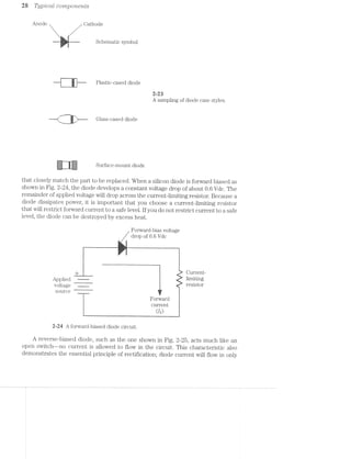
![Active comporicnts 3i
emitted light (i.e. yellow, orange, red, green, blue, infrared, etc.). Like ordinary
diodes, LE-Ds are intended to be ifoifward biased, but LED voltage drops are higher
(0.8 to Vdc), and LEDs often require 1.0 to 35 mA (milliamperes) of current to
generate the optimum amount of light.
There are two other diode-based devices that you should be familiar with: the
SCB. (silicon-controlled ii'ec'tifier) and the triac. You might encounter either of
these elements in your printer power supply. An SCR is shown in Fig. 2-28. Notice
that SCl~33.s are three-terminal devices. in addition to an cmoclc and a cathode, a
gate terminal is added to control the SCH. An ordinary diode turns on whenever
it is forward biased. An SCF. also must be forward biased, as well as trrlggcrccl by
applying a positive voltage (or t'r"2lgg]er' stgrtctl-_) to the gate. Once triggered, a.n SCB.
will continue to conduct as long as current is flowing through the SCR. Removing
the gate voltage will not stop the SCB from conducting once it has started. lf cur-
rent stops after the gate voltage is removed, the SCR will have to be retriggered.
Because SCRs are three-terminal devices, they are often packaged in a fashion
very similar to transistors. lvlost low or medium power SCBs are even packaged in
surface-mount packages.
Gate
‘= V
,
_ _ ~.-»~=¢. =-*=+--=<=<i-.-.-.,w- -
W, ,, ,7,
1p,'>7r(/125%-¢-7'
.U?U‘-1%
E-. ~, -14.-in-. -»: 1.4).-»-; Q;
:‘
<~.~;§-pf» »(-u.,:#1.
, “CB schematic
nibol
Ii
‘F’
iiK"%_%_1+‘5‘E;ii-%‘
-+~€--1»'-2--r ,575%"‘*‘~§~'f-i~‘*Z*‘*‘-i<'*"4=
§%+%_J,
-,_:,§,__,,§,..m:<
-um-"‘?F“'i1“ ._n=u'T'“u e I 0 0 w "3
at-:-1-:-:-:-1-i SCR ini at| I: , 8‘
]2=:'::::::':"-§:;€‘:i§ T992
“‘ is
1.) at package
+»§~ -%*_§,§'
sir ~%;§_
_ 4'
. . . . . _§_
.'..'.',’. ; -§-
. . . . >1
--rig
E» ~ . = -_
X i I I i
‘Emu » - - 1,
. . .£41
F‘. I:1 .5:g
~.‘§';_§;%'
:p3;.rglm‘?1-J;n.:-:.-“era-'1r:<’;::z..~‘. -{H
:a
=-.-_¢.-;::zv.v2:»;¢:a=~2r.1>
6' 5913111 all
SGT-223
»§55§5555§§535_55555§ surface-in.ount
p3.(";l<;}1,g@
2-26 SCB schematic symbol and package styles.](https://image.slidesharecdn.com/ozgdplurrtdj8c4ktjrb-signature-f36449d24fae8f28749ba408629a60e09bfd643da03035012a2b233e7710df3e-poli-180806114914/85/Easy-laser-printer-maintenance-and-repair-37-320.jpg)
![Acnkue CiO’l’l’L];)O’l"Z,63'7*"Z,t.S 3&3
ufacturers or cross-reference data book. Classical diode part numbers begin. with
the prefix lN, followed by anywhere from one to four digits. The JN pi"efi:>r is used
by the JEDEC (Joint Electron Devices Engineering Council) in the United States to
indicate devices with one semiconductor junction (diodes). Classical Japanese diode
part numbers begin with the prefix 1SS, where SS means smctll S’Z1Q'l’2.-Ctfi.
You will almost certainly encounter diodes with many unique and arcane mark-
ings. Fortunately, there are many clues to guide you along. Your first clue will be the
white (or gray) cathode band—at least you can identify the part as a diode. The sec-
ond identifier will be the silk-screen lettering on the PC board. Diodes are usually as-
signed D or ZD numbering prefixes to denote a rectifier-type or zener diode. Once
you are confident that you have identified a diode, use a cross-reference index to look
up the suspect part replacement or equivalent. The specifications you find for the
equivalent part in a cross-reference manual will closely (if not exactly) match those
for the original part. There are many semiconductor cross-references available.
Transistors
A trams/2lsto'2" is a three-terminal semiconductor device whose output signal is di-
rectly controlled by its input signal. With passive components, a transistor can be
configured to perform either amplification or switching tasks. Unfortunately, there is
just not enough room in this book to discuss the theory and characteristics of tran-
sistors, but it is important that you know the most important concepts of transistors,
and understand their various uses.
There are two major transistor families: bipolar and PET (field-effect transis-
tor). Bipolar transistors are common, inexpensive, gener'al-purpose devices that can
be made to handle amplification and switching tasks with equal ease. The three leads
of a bipolar transistor are the base, emitter, and collector. In most applications, the
base serves as the transistor input--that is where the input signal is applied. The
emitter is typically tied to ground (usually through one or more values of resis-
tance), and the collector provides the output signal. The transistor also can be con.-
figured with the input signal supplied to the collector, the base is grounded, and the
output appears on the emitter.
There are two species of bipolar transistor: NPN and PNP. For an NPN transis-
tor, base and collector voltages must be positive (with respect to the emitter). As
base voltage increases, the transistor is turned on and current begins to flow from
collector to emitter. As base voltage increases further, the transistor continues to
turn on and allow more current into the collector until the transistor finally sa‘l3u-
rates. A saturated transistor cannot be turned on any further. A PNP transistor re-
quires negative base and collector voltages (with respect to the emitter) to cause the
transistor to turn on and conduct current. As base voltage becomes more negative,
the transistor turns on harder until it saturates. By far, NPN transistors are more
commonly used in small electronics.
When a bipolar transistor is used in a svvitching circuit (also known as a (Q17/'}"’L'-'l.>(,’-7"‘
circuit), the arrangement is often simpler as shown in Fig. 2-81. Unlike a transistor
amplifier whose output signal varies in direct proportion to its input, a switching cir-
cuit is either on or off--very much like a mechanical switch. Laser printers make ex-
tensive use of switching circuits to operate LEDs, solenoid clutches, and motors. The](https://image.slidesharecdn.com/ozgdplurrtdj8c4ktjrb-signature-f36449d24fae8f28749ba408629a60e09bfd643da03035012a2b233e7710df3e-poli-180806114914/85/Easy-laser-printer-maintenance-and-repair-39-320.jpg)
![Iii Tj’_Zj]3’iCCt-Z CO’i‘7?,j;90’l"ZL6’7“'2.l»I§S
+i/dc
lnput .
signal A simple transistor driver circuit.
LT Vclc
-~— 0 Vdc.
Cutput “W
signal _
-rfifi
ag: ,r“-
fl}i-_-L
|'’|'|“.
‘I
typical computer switching circuit uses a digital signal from an lC as the control sig-
nal.. When the control signal is at a logic O, the transistor (and its load) remains off.
When a logic i signal is supplied to the driver, the transistor turns on fully (satu-
rates). Current flows through the load, into the collector, through the transistor to
the emitter, then to ground. A base resistor is added to limit current into the base
from the signal source. An additional resistor might need to be placed in the collec-
tor circuit to limit current if the load is too large.
P/tototunzs'2Istors are a unique variation of bipolar transistors. instead of an elec-
trical signal being used to control the transistor", photons of light provide the base
sigiial. Light enters the plioto‘l;ransi.stor through a clear quartz or plastic window on
the ti‘a.nsistoi' body. Light that strikes the transistor base liberates electrons that be-
come base current. The more light that enters the phototransistor, the more base
current is produced, and vice versa. Although phototransistors can be operated as
linear a.mplifiei's, they are most often found in switching circuits that detect the ab-
sence or presence of light.
Although pl;iot.otr*ansistors can detect light from a wide variety of sources, it is
norinal to use an LED to supply a known, constant light source. When a phototran-
sistor an<;l LED are matched together in this way, an o,ptocoupZer' (or optorlsoldtor)
is forined as shown in Fig. Notice the new schemal;ic symbol for a phototran-
sistor. The »vav_y lines indicate that light is entering at the base. Optocouplers are
used in printers to detect the presence or absence of paper, or to detect whether the
printer‘ enclosures are closed completely. Optocouplers also can be fabricated to-
gether on the same inte ted circuit to provide circuit isolation.U0.9-P! Q-.3
5'-.*?'““Ii*?iz.m1,
fi-fig‘
:5‘:5"
jg;"Ha.
I"tr"...-4.-..-‘..‘...‘..‘.':,...::-'21.‘;l
1’ :::::::::::::::::::~=-: z : a 1.. : :2
l 1 1
{'1 l 5 _|
LED SGumE, Phototransistor
T... receiver
.
F: 1
l
H}
l 1*-: 1 __ ._ l» _ - -_-_._....................| |
... » ;.; _
'-I
5
H
:-hfl§3!%l€!l£2M$lH‘$!%fl'£133%IIIRRHESSI-I]-I111'->2unnuno II. 1.4u":11.- upclus0.1-0Iv- u
Cptoisolator
assembly
2-32 Cross-sectional diagram of an optoisolator.](https://image.slidesharecdn.com/ozgdplurrtdj8c4ktjrb-signature-f36449d24fae8f28749ba408629a60e09bfd643da03035012a2b233e7710df3e-poli-180806114914/85/Easy-laser-printer-maintenance-and-repair-40-320.jpg)
![Actioe CO77?,]JO7"L€7’Zl5S 35
Field-effect transistors (FE'l‘s) are constructed in a radically different fashion
from bipolar transistors. Although FETs make use of the same basic materials and
can operate as either amplifiers or switches, they require biasing components of
much higher value to set the proper operating conditions. FETs are either N-chan-
nel or P-channel devices as shown in Fig. 2-33. The difference in transistor types de-
pends on the materials used to construct the particular FET. An FET has three
terminals: a sow-rr*ce, gate, and a olrcz/in. These leads correspond to the emitter,
base, and collector of a bipolar transistor. The gate is typically used for the input or
control signal. The source is normally tied to ground (sometimes through one or
more values of resistance), and the drain supplies the output signal.
N-channel FET P-channel FET
Drain Drain
_____ ...__" ___- ...
.~' '-,
.2: . - .4“ . 15‘;--‘,<‘.><‘.¢‘ I ‘»7(v$'lQL;; I
‘1 ',<'5I§[i* “|| ‘J-:1“-§§=a | '"““ “
/I I ll I
l i I x I
Gate ‘ , ~ | Gate » ; I
ii ,1 ~ i Ii
. i I J '>>‘*‘"‘ I..»i>r.» a ma-is 1
J =,<i:;ge§ =r<v-=;:.,
:!;g:.'i-: mm:
J
an .
_. _ "-_. _.-""‘
Source Source
2-33 FET Schematic symbols.
When no voltage is applied to an FET gate, current flows freely from drain to
source. Any necessary current limiting must be provided by inserting a resistor in se-
ries into the drain or source circuit. By adjusting the control voltage at the gate, cur-
rent flow in the drain and source can be controlled. For an N-channel FET, control
voltage must be a negative voltage. As gate voltage is made more negative, channel
current is restricted further until it is cut off entirely. For a P-channel FET, a positive
control voltage is needed. Higher positive gate voltage restricts channel current fur-
ther until the channel is cut off.
A variation of the FET is the MOSFET (metal-oxide semiconductor FET). lt is
unlikely that you will ever encounter discrete MOSFET devices in your small com-
puter, but many sophisticated digital integrated circuits make extensive use of MOS-
FETS. One of the few undesirable characteristics of FETs and l/lOSFETs is their
sensitivity to damage by electrostatic discharge (ESD). You can learn about ESD in
chapter 4.
There are a variety of electrical specifications that describe the performance
and characteristics of particular transistors. When you discover that a transistor
must be replaced, it is always wise to use an exact replacement part. That way, you
are sure the replacement part will behave as expected. Under some circumstances,
however, an exact replacement part might take too long to get, or not even be avail-
able. You can then use manufacturers or cross-reference data to locate substitute
parts with specifications similar to the original part. Keep in mind that substituting
parts with a different part—even when specifications are very similar—might have
an unforeseeable impact on the circuit. Do not attempt to use “close” replacement](https://image.slidesharecdn.com/ozgdplurrtdj8c4ktjrb-signature-f36449d24fae8f28749ba408629a60e09bfd643da03035012a2b233e7710df3e-poli-180806114914/85/Easy-laser-printer-maintenance-and-repair-41-320.jpg)
![at Tyjailcctl CO’772Q30'7"L€’i'ZI§S
parts unless you have a keen understanding of transistor principles and specifica-
tions, and you know exactly what the part does in a circuit.
Transistors are available in a wide variety of case styles and sizes depending on
the power that must be handled. Figure 2-34 shows a selection of five popular case
styles. Low-power, general-purpose devices are often packaged in the small, plastic
TO-92 cases. The TO-1S metal case also is used for low-power devices, but the TO-
l8 shown houses a phototransistor. Note the quartz window on the case top that al-
lows light to enter the device. For regular transistor applications, the TO-18 “top
hat” case is all metal.
TO-18 case
(low power)
phototransistor
opening shown
.. . . . . :1!-:-"
.-
"=E>I=E=5; -:-:-:-:-:- -:-:-:-:-:-:-:-:-:
seas: :-:-:-:-:-: :-:-:-:~:-:-:-:-:-1135111; .'.'-'.'.'. {fl .'.‘.'.‘.'.'.'.‘.' $1
:-:;:-:-:-' l' "'-I-.;._.;.;.; . . . . _,.
S1‘
__,L ..
TO-92 case
(low power)
'§jE;I;Z; '.‘.:.:
TO-220 case
-=.—.-_-we-'1
(medium to
high power)
,,i
SOT-223
surface-mount
package 2-34
Typical transistor case styles
n‘.‘-'g'|'n-.-....UUGOGIU.......‘_._._._.
...
--~
'00
....
yr-__-;Z;3;€;I;-' . . . . . . . .
- -'1‘-'-'-'-' ' I v ' ' I - I I '
_€;.;.;.;.;.;.;.;.;". . -_-_-_-_-_~_-_'_~
_."-;.[,;.].§g.;~_-_-_ . - . - . . . s .
Ix,-~-,-,-,,,, --------
___§,;;;:--_- _ , , _ _
:::;:;:>;- '_'_',~,~_' . . . - . . . .
-:-:~z~:-;.:.;.§-I . » . . . .
F
I -I‘
.»-'-P’ "S
.
SOT-143
surface-mount
package
- - - . - ¢ - . =-
- - | - . - . ‘ . ..
- . ~ - - | . . - --
I - - . . - | - .~
Mediuin-power transistors use the larger plastic TO-128 or TO-220 cases. The
TO-128 uses a thin metal heat sink molded into the top of the device. TO-220
cases use a large metal mounting flange/heat sink located directly behind the
plastic case. The flange provides mechanical strength, as well as a secure thermal
path for an external heat sink. An all-metal TO-3 case (not shown) is used for
high-power transistors. Two mounting holes are provided to bolt the device to a
chassis or external heat sink. Usually, case size is proportional to the power ca-
pacity of the transistor.
Transistors also can be manufactured in surface-mount cases. Two typical sur-
face-mount small-outline transistor (SOT) case styles are shown in Fig. 2-34. Due to](https://image.slidesharecdn.com/ozgdplurrtdj8c4ktjrb-signature-f36449d24fae8f28749ba408629a60e09bfd643da03035012a2b233e7710df3e-poli-180806114914/85/Easy-laser-printer-maintenance-and-repair-42-320.jpg)
![Acirzloe covi2;poi'2.ents 37
their small size, Sl/[T transistors cannot dissipate very much power, but they are
ideal for small, low-power systems such as computers or printers.
Transistur niarkings
As shown in Fig. 2-35, a transistor part numliier is merely an index or reference
number that allows you to l.ook up the equivalent components or specifications for a
part in a data book or cross-reference manual. The number itself contains no useful
information about the actual performance characteristics or limits of the part. Clas-
sical bipolar transistor part numbers begin with the prefix 2N, followed by up to five
digits. The 2N prefix is used by JEDEO in the United States to denote devices with
two semiconductor junctions. Classical Japanese transistor part numbers begin with
any of four prefixes: f:5’i5L¢l (high-frequency PNP transistor), QSTB (low-frequency PNP
transistor), ZSC (higl.i-frequency NPN transistor), and 2.51) (low-frequency NPN
transistor). JEDEO uses the prefix SN to denote FETs or Junction FETs (JFETs).
The prefixes .351] (P-channel JFl~1l1‘),.i3S.[&’ (N-channel JFET), and SSK (N or P chan-
nel l/IOSFE-Ts) have been used in Japan.
Z‘.-'.‘—".i.‘—.‘-.“~.'-’.-.‘-.‘-l-.‘-.‘-.‘~.‘¥.‘-.‘7.‘-.‘~.’?.‘-.~.‘5.‘-.‘-.‘-.“~V-.'-T5.‘-.‘-.‘-.'-.‘-.‘-.‘-.“-fill
-.'.‘.‘.‘.‘.‘.'.'.'.‘.'.'.'.'»'-'.'.'.'.'.'.'.'.'.'.'.'.'.'.'.'.'.'.'.'.‘.'.'.'.‘
4-
....
.1‘
¢--
I
.. - I I>
<
.. -¢< ,... ,...,-.----..----I-----------.-...... ----yll
i---»-.-...-.......-.......-.-.-.. --»»----i-----..--..-.......-...‘---- -.-.-.-...-.......--~.........-»-|-i--1--..'1;¢--~.---.---.---.......----i.‘-=.......‘..-...4...--<.-.-.-.-.-.-.....-------.-.
-----.-.-,.......-.-..'-.--.-.-...-i--|--‘-~---.-.............-¢.-~-i--.--.-.-.;----..-...........---1-.......-.-<-1~i-“<4-¢-.--.-.-.-...-.-...-----.-.--.--.-.;,-.-.-......,.--.-.-.-.-.-.-.---»»>»,--I1---------..-....................------..~
Q
,5
_>.
awe»
3lV.:ir".r.ir.r
H i , Piirt numb
JEDEQ /’ ‘E2 ~ ‘ “- suffix
transistor . _ g
pmfiv g ,; (up to five digits)
i 1l l
l
l
l l
_............l i .i.
2335 JEDEO transistor markings.
You also might encounter many transistors with arcane or nonstandard markings.
ln almost all cases, you can identify replacement transistors and look up performance
specifications using mani.iifacturer’s data or a cross-reference guide. Although the
specifications found in a cross-reference guide are for the replacement parts, they
will generally match the original part specifications very closely.](https://image.slidesharecdn.com/ozgdplurrtdj8c4ktjrb-signature-f36449d24fae8f28749ba408629a60e09bfd643da03035012a2b233e7710df3e-poli-180806114914/85/Easy-laser-printer-maintenance-and-repair-43-320.jpg)
![38 ’]‘ypi-cal. CO’7'7’2.]907"Z8’}"Z-Z19
As with diodes, transistors rarely show any outward signs of failure unless they
have melted or shattered from an extreme overload. You generally must use test
equipment to identify faulty transistors. Testing can be accomplished by measuring
the device while the circuit is running, or removing the device from the circuit and
measuring its characteristics out of circuit.
integrated circuits
integrated circuits (lCs) are by far the most diverse and powerful group of elec-
tronic components that you will ever deal with. They have rapidly become the fun-
damental building blocks of modern electronic circuits. Amplifiers, memories,
nucroprocessors, digital logic arrays, oscillators, timers, regulators, and a myriad of
other complex functions can all be manufactured as lCs. Circuits that only a decade
ago would have required an entire PC board in a printer are now being fabricated on
a single lC. Although you can often estimate the complexity (and importance) of an
integrated circuit from the number of pins that it has, it is virtually impossible to pre-
dict precisely what an .lC does just by looking at it. You will need a schematic of the
circuit or manufacturers data of a particular IC to determine what the lC does.
Every integrated circuit--whether analog or digital—-usually is made up of mi-
croscopic transistors, diodes, capacitors, and resistors that are fabricated onto an lC
die. l/lany capacitors and inductors cannot be fabricated on lCs, so conventional
parts can be attached to an lC through one or more external leads. Your printer is al-
most entirely a digital system. That is, most of the lCs are designed to work with bi-
nary signals. The microprocessor, memory, and most of the controller lCs in your
laser printer, are digital logic components. Other lCs, however, are intended to work
with analog signal levels. Serial communication lCs and driver lCs are only some ana-
log devices that you will find in a printer.
A logic gate is a circuit that produces a binary result based on one or more bi-
nary inputs. A single integrated circuit can hold as few as one logic gate or thousands
of logic gates depending on the complexity of the particular IO. There are eight ba-
sic types of logic gates; AND, OR, NAND, NOR, INVERTER, BUFFER, XOR (exclu-
sive OR), and XNOR (exclusive NOR). Each gate uses its own particular logic symbol
as shown in Fig. 2-36. Beside each symbol is the truth table for the particular gate.
A truth table shows gate output for every possible combination of inputs. For the
sake of simplicity, no more than two inputs are shown, but individual gates can have
four, eight, or more inputs.
Flip-flops are slightly more involved than general-purpose gates, but they are
such flexible logic building blocks, that flip-flops are usually considered to be logic
gates. ln the simplest sense, flip-flops are memory devices, because they can “re-
member” the various logic states in a circuit. Flip-flops also are ideal for working
with logical sequences. You will often find flip-flops used around counter-timer cir-
cuits. There are three classical variations of flip-flops: the D flip-flop, the SR flip-flop,
and the JK flip-flop.
As you look over the symbols in Fig. 2-36, you might notice that some of the in-
puts have a bubble at the device. Whenever you see a bubble, it indicates active-low
logic. In conventional (active-high) Boolean logic, a true signal indicates an ON con-
dition, or the presence of a voltage. ln active-low logic, a true signal is OFF, and volt-](https://image.slidesharecdn.com/ozgdplurrtdj8c4ktjrb-signature-f36449d24fae8f28749ba408629a60e09bfd643da03035012a2b233e7710df3e-poli-180806114914/85/Easy-laser-printer-maintenance-and-repair-44-320.jpg)
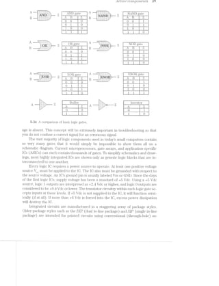
![.<1"5'
' fill.‘-22$-.v-E7.‘
3%‘‘~.-,._.<m'-i’
QHAPTER
. . ~11’ -mfg /:2-.'~’e
_.» _ . -'1
<24’ “Q 1
as 15$‘
W "1 iv =1 ii.-.i +1. ~iiv-"1. 1:. ‘.7 .- ‘%'=- ..r=~* l“.
.,r,-1,;-.1~, ».,._.i:~. M» ;§fJ_'; .-ii, 1 ‘-I;I, ii,.- N; 2"‘l. 76;: ‘Kit “I-ail 5" up ea, iii;-: = , (+9
=3‘-4 ii» <i’=~‘=. 3-an i"‘-’-in an ta‘; 1&5 Q-.. Pi‘-;~‘ in. ii»-‘-‘. ‘-=-in
ll-'
’:F"“" 1,5 t.-,. '/'45;
F
. ,_ @ .‘ 1r- v‘ -‘<-
- .. .. at ., ‘:’~ - ,fJ , Y In ~ . er..(?.»,i;.';,...~, 3*“ fix I .¢»,,,~q ..- . W .ll=;i,,. ZS: ~.:‘-5‘-‘§;"==' ~~f== .15 I » -A ,._...;-+.-,5 _..-1-.-i;,;‘_>_, . _ .. __» = E‘ W
1.
‘»r7$.?‘e.;:.-
.i.W fig
xi?"
'4'?’
A
“A. _- . I» 1»; Y-mm i..,.i| . . >5- H ii».-» M’:--‘ -.=»
ii»:-». *=>'::.+ 3.1,: qr <- , I. g,¢-gs» "W1 -‘--1-=1 -‘r.-:‘ 3'F.‘i s'":""
' i‘:..=' ;-‘ “.4”: ‘~5'»- "M-'-'=~1~'-*1. ~:--‘A Wis}, it/it i:_':1‘ iiéfl FM :;=,-,-5 ___ ,_->4‘-i F-‘st n : 5-s-=¢ *'-~¢I=.>>-»+ :.<;,».. ,.».1=.< 1: '1 »r~r= .=w,; '~"-21:‘-.1i = I.
Up to now, you have seen the features and specifications of laser printers, with a va-
riety of typical subassemblies. You know about their major electrical and mechanical
components (Fig. 3-l). This chapter inti'oduces you to the tools and test equipment
needed for successful laser printer‘ troubleshooting. If you are unfamiliar with test
equipment, take some time and read this chapter carefully. Experienced trou-
bleshooters can skip this chapter, but might need to refer to it later for reference.
. kg
,_ayisffi
41$
»r’;<?r
~>.
/~"
,£9
H»-._ >.>.- 1 »-<,, /‘r'$ »¢.¢<w»~ 5V)2|~o $ >.1--. / I! I
M
/
.1;
’*/v;, </>'*,~<:_ - '1'w‘?i:j‘ s>'-‘xiv ' ‘ '‘"~/f::_.1'~ ’* "icy/“P 1- 1' ";‘~‘Q" Y‘1.=<;;>.- -:-2>',§;,-':‘~2‘=;’>>»‘-‘u<i;:;=;.§.-;;:;£%1:r~~=:i:1:I:=:,:§:;:-'-.=rs:1:1:I>2;1:'»=::;:z:iri-;21;1i '-am3;=:r:1r1sz§z3=:&=':z:1s5"1&2rrs:I:Is<r:=-=:=:=s-:=;=:~:-;5==:¢' :I:=;'~:1:ii:1:I::=~§>122:31:22Q=:1:1:;2=:Iswat’<:;¢>¢=;1;1=1;:=s:1:r;I:nzw:I:g=1=: ;::;;5s;1::=§;;>j§:2r§$€@
.' -~ ~ _ ‘ ‘ , %-‘=- ‘>1 -Hi,’ ea '-‘>~
‘ § ‘ -Q» . ‘ $9 ;‘#4§ _;
' » ~‘ ' ' “ ’ “‘ 5 :. *1» ‘ a~ ">1'»,“ ‘~’<""’¢"r". an ‘ ‘ -'1. '57!'5§5"'4:-.15¢IF:I'7""Z3‘5$:Z€:-5I7I5:3'*~{l:§7F, , ‘3-~ " ‘ . ~~‘:"*v?"A‘/<S»"‘~¢,'~'1.»/,°= »§ in W J A./r’~ °> '=' ’1>'_:T>~g;
.. . . c. .
/-
~‘> 4, 1; ‘ < ‘ ¢. '» .. .. .. A. ~ . . . :-».- .~,- . .~ '--/v ' -~--- ./-'
> ~ a ~‘ . ...4...-.it.......>....1.;..::a:@======:r;is:zrE=t=its22¢?=£=:=§$1z=r=s=E§=2s>;~;;2:s5:35:2is=::s:2:.Ee:2>t==:z=2:252:15:5:2:21212%::>:1i==was21:=:1ir:1>==':fi=:1¢<5=1=11:21:1>'='=‘:==>r%':1==:=‘=-=->-"II "==i%i.%$'~ r><<;1<-=-=.>=‘.&+*‘§>'-IVE.-'.:2=:=%=='12>:-'=.--_4?<;
;, ‘ ~_i,' .§’I‘{-,l§I;'.fI§f'Ii§5,§i5':IPI§'5;§$jIZiiiijr3:{Z111fj"§I§I-§I;f;If:§25§§IfI'§3.f:I=}j{:-§3j§}§:}3§:§If{-§§E§§5533;‘f:=13fi1:7:3=‘:3§'§3I3:V23551:3311:1i¢:323=I=§f¢i:lE-i1:1:‘.i¢$"if-Z‘? .- """"“’"¥:T‘I?lt*-'-.1:I;121515.1.-.'»1;?--2'"! '-zipi " ‘w, 2 '4-» <‘s‘--r:§¥=-I~1-=="<<-~==>f=§-IR-'"1-=j'-1}-'-- ~ 1', ,~ , ’*_ } "5 _
§. “Q!30- "‘<-ai‘:-iI;i=i~€.if=' .»;.._~._~3_i=_:_11;ar1}=,;_-=.iw»=~‘I.=;=i='2‘::~;E»<;I5==‘-11?-I11;:3-I-1?‘;5:'?;~I';-112':-:=.:1-1'4‘;-115;:--;a1_;1;'i‘:¢;-:--;.i-.. "I2i1:z12¥;¥'{firi;ieEei@€zEEzr.i‘»&gQa’‘ ~ A <_».;.1:}:;:5-Y . .. . .. . ,. , ,..:.-'11'};»’;'_:'.'.I»’,f.--':.,:'.:'.3',:'.-:'§jQ:-j;';‘-‘,7’Z-3':-‘»}'».§'1'I.'¢;I4'* ~21-~§> -> "’*.'j;r;=;3;:;5;-=.;;;Z(_-==/~,.5 .3 .~,,. ~ >3“ V ~ ".i.$‘.{" . ‘ 2» Q7 '1-5.41;;g=§§;c~¢§>=-3.--'‘4gr , ,u 4:1£§§iI::€:':I" v,- gr >’~. ‘ * ‘Ex21,’. I §=§’>2§’-> ‘ 5/ ~é§, ~ <'§§§Q""}.75;~ 5,; ~’
$r 12 ‘MQ. "N _ 4.’>:>:>jfj.‘ ~${ ‘ X ‘ “§"%»<'* .,s:=p .<»~~»—r" ,§,Q 4% S Q,/‘I -: ,‘§‘---'~~/ -./>/_
~‘ I » v . ' < ” . ‘ an ‘¥a~<*- . »¢.i».>§$» re =.>'..i'~'f%‘>§>‘2“i& »~~‘> »..>.e'*:»s(<‘ ““~ 1 .»/~ * '
»m=sa¢~vw'“
'9»aé /r
‘w A5%
.a
.-»@.w~,
w,¢,_.1-R921 .'}’%",%:.°.Mfr=5-?;:;,i..:>>.**>r.~/grxy‘-.:‘<M.<-,v»-~ J‘_‘;.,,a*§§''9”.‘-,.~_
3/» - -» » -. .» ~ » » _ - '. 1 “C; ,. - 1..<.::;/~ -‘=1 ;1;1-.2;;1;g;;-=:{==:;._-_,‘;j- ‘. __ ‘I ;_. ‘.':~“',/ . ‘ . ~<-~/,,, , .
-. »- Y. ~ 4:2:-s»;»:> " ».=;r;1;=;'=.1;:;=;-'. $2» -~ .~w- ,~ si
I“ ° ax -¥f~'1:i13¢?i". -~-»~;'=»=@.i ’ .4 Hi, “'-»._. .1, -:- ~ ' ‘.'::‘.'*#'if~.$‘3'{',R,,v‘:j '.Y?;;,'.-1'-;i;-: -..=:;'»5: '“;¢:;:>;=./>;>r».-.~.§<,9 .+ - - </- “I551 , ' * :¢~;~'-5:i.~ '>=;>.;:};f<>n<‘?3"<;-Ii
P‘ »@'r,i.* ~ ti:-an ..»._?%;>.»-.. i <- c '5. air’* - ='~ ' -<#:~1;:'. ',<-.._:==-ri.‘a,~~'~Mia-':;w ‘;.'*72Nz%?tt$§¢‘YQ?§i7i'3$i‘I¢3)'13'$QG=2¢'i$355>“bE‘$[4‘¥§lti!€$’%371‘*7‘$‘1€'?ml¢-@7~?""L"-"’fi‘i}¥!*{1J:‘$®C'&1!}-E-TSQQ-‘l =1-.2: ~=r<='=2z2=¢:;:;=;=;:;:;-:2‘Ni r . av s '» i» / -».i';;'
=. - ..~.-..Q;:11;:=-=1;-3a;;-;;:=;;¢:¢;-'=r==::;-'1 =7~‘.'l:i:§1:1;E1:1:§<:l£=:-:-..7',‘ .;__ - r . ~ )4 I -. it .-,.;;-=$==¢s
*‘ * -i " i» hiI - .' vi?'L¢"7AI-i;}v:(*§»)1£¢}'31f_'f!q2~:r‘fQr:;¢i(¢- -‘‘a'1". .- ,~_~;:?>>.€€'Z~Z~§Q1-72-}$'>L-)H1-715>'-1-j-1-1{~Z~§I’-715€>;>[-1-141*[€%-ffl-4}f'.(¢:€~£q1j>I>§'."-119.3%-§j4}I’ »»»;-.~.¢»;»;. .;.1.;.;1.~,.;.;.;=_._.1-aw “Q ~ ,. - A?’ »;r.
» >‘?¢*-*-§r>'*1='-===11’= T,»'~-i'='g=::i&;i».~:1:¢2;:-::~>°7:E§I:1:aI:15?:3§i:I$1IthifsfaY5‘:Fii11:1-t’€':1$:¢£F:35:%3¢:1:1:1:¢>'$3:4%¢:31$i-?'=:i=-55:‘:?:='I§§$~1i=1I'fzf-1-f~fi:=:£hI£';I'1'=-I"=F ‘ ,& #29“ '
' ’ ~I »i<i=ii52Ez?F~'I1I - ' —"=.‘z . 5» >-' .+>‘~ -‘--.- *-».*=-f;:»j=‘:;>E: . _ , ?1:E’=:?'E 5:;-I Egg-_( - ‘ -9,
_ Q , :;=;*£ ' ""é;§z§z§;{&§;;‘;£;§;;=;: <~;;q§>,§;:i; ‘
= . §fr'/ i 4' "
Qgl uplgzfiizmllzjzggfitém ' :1:E3'11:E5%1:':?€3:IE'2=-2' ‘ "Q" § 'Z'<'@3»§§_A . ;;,»;,;;.;;,;*.,k;;;,.,;.,3..;.,._,,,.,.v _ _ =.=a;.;a.&;=.;.»,.;g,,&._ Z»
, .:}:I;i:’_;.,.... "5-‘=13?'ii'f‘i§?"i'i'?'1-'-‘YT-'3- " 1‘5'*“§51=l5f5‘v17i??" .»="'%¢‘ “C9 I '<’%-
ién. "5"':’*.:."’§"':‘fl‘77;‘.1"I"_l3-':'*§;." l'5I35?§1}‘§'ff5"i:~§
W1 :t ‘ ,_;;;:;;;: - _ . ;_.1,¢¢;,-.;.§~ ,,@i=>_i,33Qg);-,;:;r»,¢;.,;‘
‘;_':-‘ZIE5:1:=:"‘ -.:..;: .. ., <,. H . » - » £§‘+'i;.>=:e>I<f'¢l.’-1§1s¢r--I<i=~i
.-‘ ",=¥s1&%§sis===»;.; . I.’."1:‘“Q4’I‘1-inV.;;$€‘I1€§:§*7Y'1§‘%{7;:::3A .~ ~ . "
, _ .. . <:v‘:~%"':?=§£:==>=‘5":%‘"."if Y . . »
* ‘~ “':1i1';YE¢%"' - ~ . -1* ~
I‘ ' ‘~::'=:;=z:»:..;..».; ' ( . ~ ' * ‘* ‘ I i: ;».*-:»=-:-:-:-.- ‘ ' .» . . . ' Ii’.-"2'. . - ':~‘r.=-=<>.~;==.:-‘;<'->.~:=
,/51 ». - /‘ ' . . _ .. . . . . .» - " ' ' -"'E=‘1,§g.{-‘:'-,=;_~¢‘?i=i. . , . _. . __ Y , . -'11:,:.§,__i.,a_._u..
<> <v'»>-I-2:-r»1-'~ ; . - 1 _ I ]"Q.;‘gj1‘3‘-‘;I?ii7:l'l§v
-:»:,:;:;:;.-j.¢:5 . .- » ~ . .. . . . . . ., .. >§.. "2-§=;*§'.‘¥' L.
1 - _ . . ., .
.
" '
/ H
=?.i’1~I1:i11i'3?%i‘?- i Q?av‘-£1’-‘<»¢-e;::v1-;.',:':-,~.-:- v/P ‘¢.2-"‘. VJresyam~<<=»$,<=.=»v=<=-.1-: is-’. >2 .-
, gy _. _~§3>_,
"%:~1
iii,-<>».ag
er
L. Z52.»
'<i2l~3-:
r>’*‘%‘a>/
22*»,Q3
/~=‘ ~.€’§ ~'=?
< %~"~“.'-‘~‘::.}i:i:§7§:5:;' ~.=»:.¢a:"<’ ‘M.-“'>x A5
:-‘§:<{P;>.1.‘§1-I~i1'§-¥‘a~‘.-=;-;.;::=5.;:;: _.;w.. .- - .: ~=---.5-,> ,)‘»>,§ 9:‘Q-.~}1>>-‘.1./€j:;~;:’{j.‘»/'4'-Zdfl‘ =.--. 1 -- .- ~;».»-,----~ :- ~» .- .a3$~%_ »
>.§-.v1<4-1‘>.-1£<-1;£~::/§x-»;-;-»- » - » ' » 1 ~w~ -‘ ;.»;<:<;.~?<=<~“ Vi: ~;‘¢»y.‘-3g <.,m}§
. . . . .:.z-3-II: 1 .»*:»'..=:.¢Q<<,>*~‘3/f:;;§s’§.€;,=E
-=2-::w.=:-.'1¢:¢f:1>:ri¢..?r:f'+X = >- :- '1-:~-r‘ 4'.-‘.__--,.'v.¢>i-,.:}4:',’2c';:fl;'{:-E?‘t¥$3'X‘ = ; 7‘ . .-;;;;;:;;»; ~ . »»*2=gq'rg;=;5;==:_:_.,, ;;.:.;.;;;».'-.' ' .», . ,:
11-»::=.::;-.:..;-.>.<»-.-:»::=-112=111»:-:1;:1':2:::.'».a:»>»»-":':r:»='»=.=."2 "‘Iii .;;2<§;:;.;=.,-:.-> ~ ;.;;==.-;»;>:rg?'>:,_.. .. .,.. .< W... .. H 4‘. 4 ,_,_,_,’.M>s.,, ,,_ Kc -}§ ,. _t_._, _ .§3Q, ( _. 4%) ,,.
“_* '5 r-{w'&"- - '?‘< »"‘- '_.__.:.~-._$1 -"';.'I';:>;'-*" ~ ‘ Q - '3> "X 3 A ‘ 1»
at
M?
ca3%
'/F
1/~’
-av/1,.
’ m’
P».. .<r~'tr’->.Y4-,.hi.2»;
911..
e.1,»if. »*=;r‘*‘é%~r-‘/~’"»= '-es:' '1ae
.~'_11/,
.-,'1/KN'~;/459$tame’" JIMa2 -'3"-’-'~“~.~.4_-2,->_¢-i~/->.
i.&‘%’i1*;.
i....-ya".-$”;¢ ?~,-3,.
‘A'-/-1*1.1"!
9;,_
~»-.»--’'.¢J’?4""§é
/an.'°‘“ v» / %/.{~43‘/I&
TandyOorpora
_..~,‘-.-1-2;::§$-I-.;;-‘tits;-.-2~;;._,- _. . . . . . r . ’ 1* ,1;“- ;=...' wwwl‘-‘~"“"w. "1= ~ ~ ~ » _ , ~ _
r . » .» » , aw -':-5 .. ~ at e .. hi)1)"-:=:<:-:1:i;[-:-3 '..<_;. . . . . . .. .. .. ._.. ..=,..,,<»,,,4,,_.,.....»...,. ...,........_,,.,..,,.,,,...ii,,.,..a_t~.~<.ai.._,.,‘....,,,,!,4.,“.i:,‘*=.. > ,_ (._._.,_.,a, 9 . .
"2':24?"13?:25I‘315$?’71=§¢ZIi§§§:hI§I'&§;i55:1}-‘ii. ’ ‘ >>;;;=<a1:s.1I:&i:‘=:i;=.1-1':-» xi;=-1;!/’>51:1;!-E;1:l<:?.1:15:t1;s-:-:==5»ran-:».:»::; ~‘ . --~'»-' .--ii!’-Wit1iL7>Ti%h~i15£'E<mfi>5‘=&W’§:§=1‘w&§1i3$==!{wLd!@Mil?i%1"#‘l.:+"&=¥$1-l‘§£iF=P>:‘< gee» - - Ir.->:1'-km - ~;=/~.¢14-»:i»->-<-:-1->1:-1-:-i:-1+»-»-.-~..»-. » . »-:-.-.».»:-»=.=-;~-;-.~;:-.-.-.-I->5 - _ U» -~-1> '~ ' ;:--.-:-:‘:->:--'1»;>:=;:i-tf-¥=kw!<-1' . ,:‘;>";.‘qI-1>fi$<>.éw:Q{@&i£-nwnqr=v1;=,;r15$9?-ark-w-1pQq+u;;1§w=;;¢':'¢g@$~F%'~Q>‘ *-;é---~--"-"~ i .~ -.<§ > »J.¢>- _4-:¢’-_£5;:5§2§u-f>-<>§~_~;*»'j;'2' -- -:_-»:-2.1»;--*4--~;;»-~_'»-4,. * *,=,<r . ~ r ~ >-" »="~*' - -* ~ ~ ’.@<=P-1/.%~".~f»==. *
" »‘»=*¥".§3-». l . K
~ ‘ ~>’ 1. ~§ .=;.r»i==‘.’ri»"” " ». 3- »- _- ;
3‘ ’ ~ ... ":.. . . ‘ . » . Nara ’
H ‘ ‘ r . .-.I.f-1-FE-_»;j.I.,.. - . .. >.““‘II‘> .- . . . ’ ’ .. ;,-o6<vx“§':“ H
I -H. . _ , >,,.A.,-_»;:» (4-1»;-~§%*'.‘.‘.‘»‘.» ;;.- :»,-- - »» .- _
. . . .. . _.; - ,,;jI_iji‘-.;--1‘ .
‘ I .‘:“_‘*i>>l‘';i;7>"i’€;-%V;&$3;$£$:)‘;‘fA;¢fi:T‘::‘ I ’ .». .3 .- - . . »- a2:5:;-5-§=3;}:&;=§=E:ii§¥I"Q 015%’ 8“5~».=-'.155:=;:E:;r4f-:‘31.=»'». ' » . . »» ‘»;».»»=»-/.-:I~:+‘>'¢-if’.'.';" 1; - = v 5 -..=»'.'-.-.»,.»;;r,;,=;i=r§gzi»*»1’°?*¢?“7“I’»-- ~ 11--J -» ‘.5:1»»_I;v'{1iE:?Q;&fiztifiéfl-El:5§:»:-:15$1515?*‘§2El:125‘E355li!5i5f5 - - ~._./’~%:
~ ;;,>a;a§s%¥k1+@i“““‘”’"i‘*' " M’, .¢.l7"€i§ .
» '
1
~ - » - - ' ' . ,= -'."i:' -. I'1. . l. -. .1- .» ---4 .4" '$,‘{‘,=:e..kI;:1I11Ei5Y;’:'§§5E=> .. =‘;r~».-.-112-.--;;»-. .- ,. . .. » - .. - >.-.--» _-;<--~ '- . - .-~z->~. ~. '~§~_,, - > 2-.»;-2c~-.<;§--.»>;-@,~>-;-;--.:- < .. » ,.:_._.-,,E_:,_,.. _ ‘_1-Li:-I:;:€;;§;§?%:$fi;§€§_;§g%g>ff fifi 3§_K/2 :1... ,_h. ,§,:~§ C
-1-: ' ~‘»,.¢: ' » W» "fie.
~ . gpggl ' = ' .9
:I » - “ ~r»...=,>e< . -i .-L-.Ei»e=1€‘£l‘¥$;‘k"‘$“'' . -—-I 1 "—):I(§I—)"—‘7'—‘¥'1311-1?’-I-j/Liffik'v-$11»:k-;(:'(’F_q'§E;_»1}_Q,§, §;fg~ ¥ "<;g:~- > - __ .5. L:-,»'r,¥§§?ffi‘-lP-_q§'l,l§3‘¢H£'vV}J.¢.,_.i/r e1»>:;-<.-,,-<-¢~>,_.~i>.;Q¢=_ii;3Y»-Q~ ~ -'-""-‘-I:5i’:F3ib'<-1M1-2-?!*1-1+3:>12'Q-:4/*"-'-'-I»L>‘~Ji-‘-"04&3“-'‘ -- > ,~’<r’*< "¢v.v.-I:w»-‘W.-'-l:i:1‘fl=~€'"'“M ‘- ~' ~, "-2.:--=1: '--<>.-s:1~.>E>.<-:»-/»:~-:§h¢;e=;-<->~1»>s-iii. . ;.».-.-.;.;4.;» / >l-‘~"'-".-/_'.>>_'.'-.--):_~.-.-.y~_-in--.-,'1».~.'.-'!A~?§~;<-.§2L~-<§- .1.+§§»,~,.q.<».~ » q ,.-...<m;>,.i=¢~--ivyi.~~.»..i-¢»~-:1--“ea /'!;$,~1,.--'>,§i7‘/,:'.-:.~_v~,--:55.-]H>.~_~-i'.-.>):_u>f'/,»
- -'-1-re:-:4:-4:§¢$;~/9*»:-$T<-Pact£9-:15;-:<<<»,-_>i»: »-'-._.-, ,»-.<,- -. V ,- gt.-,lj._')I>?'-H§HJ1';:1T;‘*'¢l-w3&1§1‘§.'_ - ' 1;y£§<fi1{§;};5?'§§fli§£25fi-;’¢j;{1§§-I¢,‘;ii;$'-13115.1-$1131
I-ea; ~ . ~;.~..-1 -.<:§*_‘f"
. * ~ . ..-J-,::..;.-._.-5.5.::e:;:a>:=:-=.:are-:i::~-z:a2z:-:1?==:<-="-"’ >
._;1.1-5.3;, » _ ,._,,i;=:;=g.1--1» ~- _;,-.5; =.:;:;:;:--s--1-n‘-"~" ~' ,‘.j.§-:¥<‘_:-'-=I',;‘ '~'¢;iiJi'~$>; 1-. ' ‘ ‘.‘=“.=1.~ L""'~':1"."33$---11:‘7§;§E7"{.'“l¢"Q_J5f¥"Y-]Ew>:§‘Il‘<‘- .» _ .1:->'-3>5;$-1¢r;;.§u;§;:;e;@;;;2;:1::;z-~ 11;;: i I-’-I-1-‘/§1'-’2’.-.I>’ . ». . -. - . . .. .- J:§,i‘*3"{¢4gt» - ~~ <-~ -._~w--Y -. ~... -- . - - "1 !" ii, ..~ ~r 5'€?1{)')~.'|';1-.52-}.»,¢'.’.-.-<-‘.§';.v::-F»::70" .-r. . - . P .» ». .. -- - "fig =i-_»;a~'- ‘ i av‘ '~*~=» Q; ‘r ..’ ":~aw¢» H ‘W-‘z~£_i= 2;»;,». . v x ,~:-r ~*-/' ‘";=‘ ‘>
§ 2'? »~
¢_, 1-». 9 ')5;A(y -v-';w‘_Y ‘A4 k_~.(,‘>,_;,< ' it
.. .. .. . - 4-" ‘< xx ‘ _ ex. i ;§i‘{=€_.w.~'5>...M'<<i».- "' >-‘ »arr-.'-_~:1>-:1:--;":>£:3:z§*-:--iii:-1:521"'~ . :-‘E/ ' :r~= . - . . - *4 ct -. -8 “"1-f:-' -=<~: ---'.".=.-.-.’i'-.¢~t~’} r lv -;-.:-r:=.1;:r>.>.fi-11-'».:-=»:-:-:-:>i<;<-.-.@--L‘ ~* 2;:
~ r i; .;.-I 1 .<~.5*=§'}-*~i§‘*>>§: -:.’ -F; , . »
"3. ‘Jew’é t ' ‘ - » '""‘~'-‘r“'1*"i»'<<:e§rr‘*‘ ~'*’~* ‘i /..°<~;»§<~e1<.<~<.'.:.§.~:'<~‘.:m~i~m.»—r>~1.;§z§a»»m@ A. §/ §‘§% *1
- .< . . .- .. ‘~, ~- .. .~a - Q < tn,.@;E:>1£z1E-BE-;'¢:'¥-I1?‘<-<4--=1Y *- . ;s=.. =. 3. -. §><>- ' ' /, ~ . 1. '§t'=~‘§ =- WSW - - “ .- » aéai
".:s;:»-»: =amt?=1.-i>;§f¢3i;&:i§1:£i»>W»=(--i"Y~(era cy .§‘v; ’ - , ‘ - ‘ ‘ J , " - ‘ - _ _$»'.»'.<g.*‘j-‘.1’.‘.<;j5E;i3E:iI§53'~i ‘ ‘ . , ;£
. ( ‘k 3'9 '§z»?* ‘ ‘ @§‘ * ' " ' '. II) . . ,., A .,...i~ .... n,, /I/&~/'~. § }1?:}(=§q; - . » . 1*-';I
3-l A Tandy LP4-OO laser printer.
Q -=“W=*~_>'%l<'-.‘ re;’“i<’:»'i¥?&.‘:s‘:=-.'i:~:;,‘*;‘_x€2.., str2.;~..iT.<i, ,, . . ‘ ‘ *1 ..
""21;-=-1. . .. ...H.:2».-.5»-:25.».».=;:.=..1>.;::-;:If:.-f'55:1-:15:-~;<= =-*'=:"=- 1~ .“~ “lw . :“, 13* ."'* >‘s?"§%‘/"‘='?-?€:=A."’?‘I '-1“ --I>-1“?.*-1I"-"":-t?'-- *’i»<%’}“:»~‘-a'A1’*»‘=‘--‘ '-_ (757 r “ii - 1,9,‘ ¢<, in Q t;°~*€,/s_§.2f~};v,’i>$<,,{=i< is -in . . .
~§%?a§*'" K *1-)‘Y ~
Iii](https://image.slidesharecdn.com/ozgdplurrtdj8c4ktjrb-signature-f36449d24fae8f28749ba408629a60e09bfd643da03035012a2b233e7710df3e-poli-180806114914/85/Easy-laser-printer-maintenance-and-repair-48-320.jpg)
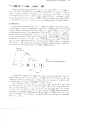
![Lia SO[Ct6'?""ZrTZ.,§] Ct‘l*"2,-(T1'.- test ’Z'-"MSI’}""Z.t’l'7'Z€"l"LZS
Because you are working with electronic systems, have on hand two sizes of wire
cutters (one small. and one medium) to cut jumper wires or trim replacement corn-
ponent leads. Include a separate wire stripper to remove insulation from wires or
components. Resist the temptation to strip insulation using wire cutters. Even if in-
sulation is l‘€IlIlOV€Cl successfully, cutting blades can often leave a nick or pinch in the
conductor that might later fatigue and break. If you plan to make or repair connec-
tors, you might need special crimp or insertion tools to do the job. Use your judg-
ment regarding exactly what tools you need for connector repair.
Any wiring or circuit work is going to require a SOtCf€i"’Zl"l’Z/Q ’z?ron. Invest in a good-
quality soldering pe-ncrzil.--iii the range of 20 to 25 W (80 W maximum). Avoid heavy-
duty, high-power soldering gems. They might work just fine for plumbers, but that
much power can easily destroy printed circuit boards, wire insulation, and compo-
nents. Always be sure to have one or two spare soldering tips on hand.
Remember that soldering irons exceed 500°F at the tip. Not only are these tem-
peratures a serious hazard to your personal safety, but they are a serious fire hazard
as well. Be sure to park a hot soldering iron in a strong, wire-frame holder. NEVER
leave an iron unattended on a bench or table.
Materiais
To use a soldering iron, you also going to need an ample supply of solder. Use
a 60% tin, 4.0% lead. (60./40) solder containing a rosin cleaning agent. Never use paste
flux containing acids or solvents, or use solder containing acid flux (sometimes
called CtC’l’-d coir-2 or pZ/u/mbe'2r"’s .S‘OlCIl6”}"‘). I-Iarsh solvents destroy delicate component
leads and circuit traces.
spool of %'2..oo/it-up ‘Z»U’L_i"e3 can serve a variety of uses ranging from printed circuit
repair and wire splices, to make shift test leads. Solid wire (I8 to 20 gauge) is often
easiest to work vidth, but stranded wire can be used just as well. You might find it eas-
ier to keep several smaller spools of different-colored wire so you have color-coded
wire for different purposes (for example, red for dc voltage, blue for dc ground, and
yellow for signal wires).
Include a set of Ctlili-,C]Ct-ZC)?"" Z-QCLCZS. Alligator leads are available in a selection of
lengths, colors, and wire gauges. Alligator leads handy for temporaryjumping of sig-
nals during a repair, or to test the reaction of another signal in a circuit. A set of small
alligator leads and a set of large alligator leads will cover you under most circumstances.
I.1Tl(IllVlClUEi.l crlligdtor cl-rips make excellent heat sinks to conduct heat away from compo-
nents when you solder or desolder.
HIQCZ/PS/'&'7*""2l’i"'Z;/{T t*riz.b/mg provides quick, clean, and effective insulation for exposed
wiring or splices. l/[lost geiieral-purpose electronics supply stores sell heat shrink
tubing in foot lengths, or in packages of assorted sizes. Use a heat gun to shrink the
tubing, although you could use a blow drier. I-Ieat-shrink tubing is available in a se-
lection of colors.
These tools and materials are only a few more common supplies that you will
need to get started. The list is by no means complete. Hundreds of general and spe-
cial purpose tools are available to help you in your repairs--far too many to cover
completel.y. Experience is your best guide in deciding which tools and materials are
best for you.](https://image.slidesharecdn.com/ozgdplurrtdj8c4ktjrb-signature-f36449d24fae8f28749ba408629a60e09bfd643da03035012a2b233e7710df3e-poli-180806114914/85/Easy-laser-printer-maintenance-and-repair-50-320.jpg)
![~_J _/ r.~'_.u,» r L"! L.-3 “F0
3‘: zélug‘ Es E
,5 gt 17$ ii 1:. 2 >-
11 Ii‘ 511; i"K. " ~2 P :1: *‘a- 2-h ll i~v,:;,
Soldering is the most commonly used method of connecting wires and compo-
nents in an electrical or electronic circuit. ln soldering, metal surfaces (component
leads, wires, or printed circuit traces]: are heated to high temperatures, then joined
with a layer of compatible molten metal. When done correctly, soldering forms a last-
ing, corrosion-resistant, intermolecular bond that is mechanically strong and electri-
cally sound. All that is needed is an appropriate soldering iron and electronics-grade
(6C*/40) solder. This section covers both regular soldering and surface-mount soldering.
aoidering background
By strict definition, sololerrmg is a process of bonding metals together. There are
three distinct types of soldering: brazing, silver soldering, and soft soldering. Brazing
and silver soldering are used for hard or precious metals, but soft soldering is the
technique of choice for electronics work.
To bonc. wire and component leads (typically made of copper), a third metal
must be added while in its molten state. The bonding metal is known simply as sol-
der. Several different types of solder are available to handle each soldering tech-
nique, but the chosen solder must be compatible with the molecular characteristics
of the meta;s to be bonded—-otherwise a bond will not form. Lead and tin are two
common, inexpensive metals that adhere very well to copper. Unfortunately, neither
metal by itself has the strength, hardness, and melting-point characteristics to make
them useful. Therefore, lead and tin are combined into an alloy. A ratio of approxi-
mately 60% tin and 40% lead yields an alloy that is pliable, has reasonable hardness,
and a low melting point that is ideal for electronics work. This mixture is the solder
that you should use.
Although solder adheres very well to copper, it does not adhere well at all to the
oxides that form naturally on copper. Although conductors might Look‘ clean and
clear, some amount of oxidization is always present. Remove oxides before soldering
to get a good bond. Apply a rosin cleaning agent (calledjilagr) to conductors before
soldering. Although rosin is chemically inactive at room temperature, it becomes ex-
tremely active when heated to soldering temperatures. Active flux combines with
oxide and strips it away, leaving clean copper surfaces for molten solder. As a com-
pleted solder joint cools, any residual rosin cools and returns to an inactive state.
Never use acid or solvent-based flux to prepare conductors. They can clean away ox-
ides as well as rosin, but acids and solvents remain active after the joint cools. Over
time, the residue will dissolve copper wires and connections, and eventually cause a
circuit failure. You can get rosin flux as a paste that can be brushed into conductors
before soldering, but most electronic solders have a core of rosin manufactured right
into the solder strand itself. The rosin cleans the joint as solder is applied. Such
rosrlrn-cor'e solder is much more convenient than working with flux paste.
irons and tips
A soldering iron is little more than a resistive heating element built into the end
of a long steel tube as shown in the cross-sectional diagram of Fig. 8-3. When ac volt-](https://image.slidesharecdn.com/ozgdplurrtdj8c4ktjrb-signature-f36449d24fae8f28749ba408629a60e09bfd643da03035012a2b233e7710df3e-poli-180806114914/85/Easy-laser-printer-maintenance-and-repair-51-320.jpg)
!['-G-U LJL/L-L.L=C/I LILU LL-{cit LL. Q1. crtutl L.LIIL.l_,.-’IL=L.-L)
Til) Cold-drawn
¥Ie ate1* 111(i‘l1Etl till’) 6 F
. 120 Vac
coil
Jiiiiliiifiiiiiz-;1§=3=:=§$§=§§§1:'>‘-'-G -'-‘:1-'~'|'-‘-‘V A
:<»:-:-’-:1<-:-:-:--‘-*~:> :-
~ .--:-.~:- -:-:-'-"-.~:-:~:»:-:-1-'-'~:~1»:-2-'-:-:-:-’-:-!-.--.-.--w.-.-.--.-:4:*-121:‘-. I ...;.;-;.-’-;.;.;.;' -2-.~{;.;.;.; -~.5;J;.;.- - >.;.~;&.;.--.Q.;.--i;,;-.-1'--.;:;C;.—_-¢-.;.~.-.¢. E. _. _:;.. .-' .._.._;_._.,.;.,w. ._._. -._.~ .1» _l .._._ . .>,,. _-, .37-_. ."_: ___ -_-_ _»-- »-
1,, .-i. gr K—K .-E:E=:;=:===$=EI-/t==E.’£E<=E=7 __ _ _____ _I;I;?¢-¢!§!E$;5gi‘;-’$;i;i;1>7;. ‘E2;2;!;1§;K;EI;1>152;25$$51-;E25;;;I;qI;25;¢;Z7;-1211;251:553‘;'!-13$»;>‘:3§»:1:l;1:;'k!:-;7';§5;!:3;-;7:!;1§5:i'¢,'"if?",1?-xi:-;:¥:-:-:~:-1+:-:-:-it-:-5*~,('m‘5,"$3“-;§",'$:3.‘-Y-if;-..‘.:Z -
-=_" §-;I--11--;i--;I3-113;I-{I313--(I--;1-;Z--ji-jj--jl-1 _' . W." _ ,j";;; " '* *~""" K . ~ -___ . -- ____;;;ji e-KKKKKKK .,...._ ;;;;jii, — "K K _::..'-. I -'-- -' ~'-'-'-' »‘ -' ...___, ,_ I. .i..,,T___ _T_ _ __ __ _ __ __T.,_____ ___" ,__‘ _ _-_-- _ _
K‘ ~ ' ‘ ‘K K K K KK;-------- - ==u2,==>=;.1===§¢=:;:=:;; :;:§,;:§cy;---1-'32:Q13!-32;:-:-:-';>»:;>‘<;:;nI§-E:=2;-1%-1'19>1:-2:;:?:;:»;§!=!=1:!;:;:;'§$;§!~'~’%§!-§;=4;1:!<-<$:1§§$?4¢-1*!-=:!:¢:41:=5-1:!-3?-‘-5!¢>>I'$2-.+'~‘..1:;1¢"':-R‘~:.v..'.-u-'...'.},. . ...,..rC"<.<. ....-...-:.<-»..v...-..€. 1...;-Q./..-..._,......,.1.-..$-.-.2‘.-. ..:1-. .4....¢.y,r.,_. V; '-yi; .-._ __.,_.=;§v . M.
===-'/.>:~<==s===:=>'=l§r¥;= -¢==ian3,;gas;=zr='1=s==s:,~i;¢s->=$s:=-",3!-==1:-,-,¢s:=*,,-rs,-=-:,ii:-53,-_,-<-»>:~g:»:+~->-,i=,»,<=i<» - ,- -£4-2'!-2*!-I-I-I-G5-2*C‘!-P "---'-'~' ‘ ‘ " ‘ 'Q‘ ., ;.-.;.;.;.;>;.-,.;._-1»--;
=:>§::’:=i;:1='.-=a5$:=¢&=':~:¢-:;:;:-:->;:-:-:;:;:;:;:»<;':;§:;.-.;g¢:;.;:-:-.;.-.».-;.;:_
1 1 '1 ; 4 _Y ' Q 1 1 1 W ' ‘I
3-3 Cross-sectional view of a typica so c. eimg 11011.
age is applied to the heater, it warms the base of a tip. Any heat conducted down the
cool-down tube is dissipated harmlessly to the surrounding air. Dissipating the heat
keeps the handle temperature low enough to hold comfortably.
Most of the heat is channeled into a soldering tip similar to the one shown in Fig.
3-ll. Tips often have a core of copper that is pl.ated with iron. The tip is coated with a
layer of nickel to stop high-temperature corrosion, then plated with chromium. A
chromium coating renders the tip nomoettctble--solder will not stick. Because sol-
der must stick at the tip end, that end is plated with tin. A tin coating makes the end
'wettctbZe. Tips are available in a wide range of shapes and sizes. Before you select the
best tip for the job, you must understand ideal soldering conditions.
Chrome (nonwetted)
Tin (wetted) Coating
1 E255
ii 1
I . ‘ #fi“ " 7 7 7
__ _.;:;:§:§:§: ..1- "' r ' .1‘.
_.;.;.;.;.;.;.*.= - .4-_. -zi.-;,-wag;--F!1,i1<c:»5;n1my -:-=a~i.:~::~i‘-tin :33;
_.);|;-;-'.' ‘___"_.-_.'_ -I-_,,-_=_.‘-_-_-3_-_<_-H - _, - _._:,_-_-:;_._-_¢ ..-" i
:-:-:-' .,|-1- :-:- :-:-:-:-:-:-:-:-:-'-:-:<.. . . ...:-.-:-7-:.-:-:- :2::1.....
1:5:5:';".-' -:5‘" ' " ‘ ' ' ' ' 21:235:15:1§:515:5:!'5:§:5:?:$:!:!:5t!:5$:! A - <~:$:1>':-‘:7:5:1:5:5:5 ..::::::::::
:3‘ ’ ‘ ' ‘,_ . F" ‘*1 EE5E5E5E55E@E5E3‘ JEEEEEEEEEEE.;.;.;.;.;-__ *1;-‘_"-2*; ~;~.-H;-2-2-1"-I-I-2-2-2*;-‘ .' 1- ,;-I-ii-Z*Z~i-i'¢4§;;;;;;g;;;;;;
‘-"3-2;I;Z;I;2;»;~_._ "-.;;. "‘*“‘¢§':»l‘.i <1:-J" .i21i~r.=.=..';~:Kwj~.='r1'~~'.T~. i:»s<=l-‘1“ "H--H-'~-~~~
-'.'.;.-.-.v.;. ... .- .- .- .' . . . .2I!2Z!1I15ZZ""‘' .";.;¢;._.;-;-,-_ 1-; .' J ~' .‘ : -' .- .- .- ..-“.-.-..n
' '.~.;.;-;.' -;.,._
' " ‘
l
Nickél hon inner
body 905151118 Copper core
3-Ll Soldering iron tip.
The very best electronic soldering connections are made within only a narrow
span of time and temperature. A solder joint heated between 500 to 550°F for 1 to 2
seconds will make the best connections. You must select your soldering iron wattage
and tip to achieve these conditions. The entire purpose of soldering irons is not to
melt solder. instead, a soldering iron is supposed to deliver heat to a jOiI1t--l1h€,]'O?l7’L'£
will melt solder. A larger joint (with more numerous or larger conductors) requires a
larger iron and tip than a small joint (with fewer or smaller conductors). If you use a
small iron to heat a large joint, the joint can dissipate heat faster than the iron can
deliver it, so the joint might not reach an acceptable soldering temperature. Con-
versely, using a large iron to heat a small joint will overheat the joint. Overheating
can melt wire insulation and damage printed circuit board runs. l/latch wattage to
the application. l/lost general-purpose electronics work can be soldered using an iron
with a rating below 30 W.](https://image.slidesharecdn.com/ozgdplurrtdj8c4ktjrb-signature-f36449d24fae8f28749ba408629a60e09bfd643da03035012a2b233e7710df3e-poli-180806114914/85/Easy-laser-printer-maintenance-and-repair-52-320.jpg)
![iS‘ol/dc?"/2l'2K/rig KW
Because the end of a. tip actually contacts the joint to be soldered, its shape and
size can assist heat transfer. When heat must be applied across a wide area (such as
a wire splice), a wide area tip should be used. A screwdriver (orj‘/at blctole) tip such
as shown in Fig. 3-5 is a good choice. lf heat must be directed with pinpoint accuracy
for small, tight joints or printed circuits, a narrow blade or conical tip is the best. Two
tips for surface-mount desoldering also are shown in Fig. S-5.
Width
1-one-v»->»o-»»n»v-04
-.--.
iét J2
-‘"‘*.~;¢ -a;’~/552
.>.,.$= E» X
v§»:<a§-sgi";
j§,§1.*t-.§-
Flat tip (screwdriver)
*<’~Y‘f-'~'-., -1 ‘rs; ~ .
. 4"» , .§. ,Q.j>< <,~< § x. ..¢,_».~~ ¢» ;_ -,6 ~?$r;:=~ "Q_§'/1}:-Yi’x:, 3. , ‘Q-,'$7»~‘: ">;,
' re, ».. 1 * ,§‘.><’Q-_>‘
{jgwz§<¢> 11%;‘.
F
l
Width
./“H
1/ -
r- -‘i,“'-7$<~,--W"-5/,
.f§{<;;3_§C;.<i
=:?*~i<i/Y;§rki
£_?§1§j,<»€i>1
19/Y1 as ’>.
i/»~~>/’~.-_,1
l.
i Mi
Conical tip
'" “< zwmw...-A. -537-3’i'1‘*.¥';?"-IX1~'i’&_?.?-‘='?C if Pl K ~*‘z;,:‘<$,w@5-<e1q,w>:.*sr-.@~*)§3;,e>g§.'>@-g>i§w3%;
. r,K,;~.»§?;;,».- --»;.-‘w-.> >5, Q:/.~ ~-6" ,-
/ »1».ax > 3
~ ».+~->@,<-'1~i-~#.>&=:<=w-a:<'>.<K ., r,..;- *~-1.’-,.;,+-n, ,,,.. .. .. '—, ., '> ..< V,-. -4 =::¢;<>.:<»:-:~;~*i“ ’=-.~&:"v;‘~4
in :.~;:i "-v ~»6 ~ =="*= '»>=:-§:<>'.~<>’<>,“<.,<»w>.;;=;,hr», ~<-;>re,§-.=~~'~<:><;=>:- i “
hv .: V, we .~ . ;.--". - '~' é"I° *$'~}'_'<;~/1-1.§$,’q,,“n ‘4_.'Q§‘1,,%_%;,{‘<§~;>¢,-%E=}}1 - . .‘(r<-,‘l7lj*,"'l_:"-‘ .11; _‘.7'/%".'¢f,§3:l'-_/KY,1";n;‘§?§’3i%w°7~§§:—;5{’:.
. it V .' " " -It as .~‘-4%~*-<~‘.*X*»:;‘>>~=~ ~"~°>;*n ] - - - i»:%'--:-1 :1->"-.‘.~’-5=K:-'e<‘-‘%~r§»;~"~
. . ,- nu.» ww ¢‘:;1. M» Q. $<-:v>.r,<. a2¢’>>'<.{wA,i.~Q~'=,.-459$/Q ‘.,?7/(— “>4 v J <=".--‘~,,i-M» /,3>;/»__~, t,._r.,~»s,.¢_,.,".-,i
§ '>“'-‘ ‘°“"*“=°
' 1
.< W: ’<‘&‘>‘:-9'-‘-.>:< K~'1L:~l479!15T':*?"?95‘-'7$:‘?I$<¢?'I1El' -.,~.<,.,,.m-
.€ C5¥'b“i:+§f1~‘Q1%§,>'£¢,,'u$¢-;¢§§§n$=4$
.~:a=a'»?$r#>:»»i-mi».-winz=>4r&;i§<$rsr~!¥ri>a*+>s=>:
- .-,._j.' ' ",_=;.,;.- ‘-.>_‘ *4"; $51:
$_¢,&§;,‘.%.-:—_€g_ >374 .5’1,-é,z,¢.
--~ 1.». Q -.,.,,, ~., ~,.. .,
~'.<“¢‘»*'.-2~~.{~.:»-a¢v:s.¢=‘:1w‘<>?,-&~.'<£<~ <'.i1'=~Z4£"I.°'-,~¢'>€~'1s~5»,~,.Q ‘*5 '3
Surface-mount desoldering tip Surface-mount desoldering tip
for small-outline lCs for chip components such as
resistors, capacitors, a.nd
transistors
3-5 An assortment of conventional and surface-mount tips.
Snlrlering
SAFETY FlRST--always park your soldering iron in a secure holder while it is on.
Never allow a hot iron to sit freely on a table or anything flam.m.a.ble. l/lake it a point
to ALWAYS wear safety glasses when soldering. Active rosin or molten solder can eas-
ily flick off the iron or joint and do permanent damage to the tissue in your eyes.
Give your soldering iron plenty of time to warm up (5 minutes is usually ade-
quate). Once the iron is at its working temperature, you should coat the wettable
portion of the tip with fresh solder (this is known as Z???/7’?/Zl’)'2,Q the iron). Rub the tip
into a sponge soaked in clean water to wipe away any accumulations of debris or car-
bon that might have formed, then apply a thin coating of fresh solder to the tip end.
Solder penetrates the tip to a molecular level and forms a cushion of molten solder
that aids heat transfer. Re-tin the iron any time its tip becomes blackened--perhaps
every few minutes or after several joints.
Tin each conductor before actually making the complete joint. To tin a wire, pre-
pare it by stripping away %;i to %-l inch of insulation. As you strip insulation, be sure](https://image.slidesharecdn.com/ozgdplurrtdj8c4ktjrb-signature-f36449d24fae8f28749ba408629a60e09bfd643da03035012a2b233e7710df3e-poli-180806114914/85/Easy-laser-printer-maintenance-and-repair-53-320.jpg)
![as SO[Ci€'7“"’Z1’l‘Z,Q drird test in-sfirm-rz»e'nts
not to nick or damage the conductor. Heat the exposed copper for about 1 second,
then apply solder into the vvire--not into the iron. ll‘ the iron and tip are appropriate,
solder should flow evenly and smoothly into the conductor. Apply enough solder to
bond each exposed strand of a stranded Wire. When tinning a solid wire or compo-
nent lead, apply just enough solder to lightly coat the conductor surface. Conductors
heat l"aster and solder lilovvs better when all parts of a joint are tinned in advance.
Maldng a complete solder joint is just as easy. Bring together each of your conduc-
tors as necessary to form the joint. For example, if you are soldering a component into
a printed circuit board, insert the component leads into their appropriate locations.
Place the iron against conductors to be heated as shown in Fig. 3-6. For a printed cir-
cuit board, heat the printed trace and component lead together. After about 1 second,
llovv solder gently into the conductors—-not the iron. Be sure that solder flows cleanly
and evenly into the joint. Apply solder for another l or 2 seconds; then remove both sol-
der and iron. Do not touch or move the joint until molten solder has set after several sec-
onds. lf the joint requires additional solder, reheat the joint and flow in a bit more solder.
Soldering
~ . 1*» 3» .. ""2"
11 _$,.<“>7Y:$}'e us‘ w, "x
. f fix .*‘Y_ 4"“ w’ A.
I
~>;,s,_ -.
{#1Ji~'
"If.
_-
.4
y‘.
"1.
/-*”~
x'2,
#31*‘
-1».xM,
4"-¢’KI
‘u“P-.‘3
7"/‘A"J ~¢.,4~<,>>_
~.,f‘.*‘.
1,1‘1.
.,_‘1*~,
3%<<
7,,-
~»
‘r
5l 44 ' A
‘..'=.~,->.,». .¢
- Solder
- 17/ 7
"Y.
X) » / A‘ 7v 1 _
x -. a :/V
.~“'»-' X‘ J‘ w’ .1!”
as ~<~. ~. ~. . ‘~.- (
.Pr1nted- . .1-. ~. ’~x=*'. . ,,*,’,»' ,9 ,e= _-'- ,3,"
c1.1<.u1t . <-»-;;_1—~_~;- . i >,.;,,..-*b ‘ __ 1 Wx J£,,m,%..‘, 1;. LO Q Q1 1 Q
oar C ~. .e2§2~s*s'1 _.<‘:;;:::;:,:.*‘_,. --—¢—<§1§ Z’ ’ ' *“"~>‘W" ~, .,e.r..-.ev_-_-.: ..:.ac;-;:;:;:-::::v::;¢::¢:¢::.4.... -,.__.:--.5-.-:
W - _‘ ".;@:.~..,.:::;.** """ .1-»:-.--v»+<<;.' g’.-»<¢<w> ‘-
., ‘P 1? :2: ::;.v.°' i
' ‘=:v.5t::1.>; _ss:>'w¢'<». ."
A‘ * A (1 at ~" ‘ .-
/L)1.~]. _ uc .01. - ~ . aw..—= ¢~¢-"'?‘.'- mr.<,'$;;‘, ,. .<2_i* -,.. 1? '__ '_,-~ " ~é¢,‘_.,>;_,;5-_,§,;§,»‘_!¢(,<,,v.,.(,-_,>,,_ 1- i
M, ‘»~..,_m,f-*-.~:i¢,<<~.-a¢’<¥~:»:>% "J ,
g‘
_M_,.. K, .
,..~”* ,1-"' ,=~t~'-*_'_,..r _,,~*"‘ ,..z' ' ,1-
=-~~ ,,--'" s
El/> ' »“" -" Me,_,_z'.B ___? A-. F».4‘>ll ,.. ,.. ,_.,_».» gt . Q...~,- - ..¢ ,... . ,2"
...~="‘ ’.e<‘?, ---.4-<" " M -' '_ 4-v4‘ _¢<“ ~:‘
ii. -<.~<' 4:‘-‘”», i__,_;=- ,<»" J-
._>>>_. _ _',_.,-» _,.,~- _: Q
’ ' K -99"“. ~*-"' ,.-J" ' ,4-.__._,_.,..._..... 5;“ ' ' _ ‘___,.»~
. be............._.......-....31....... . . . . 1an J
»»»»,. ’!
"i,,,,,,,..........._.i
as Soldering typical printed-circuit junction.
You can ideiiti.i‘y a good solder joint by its smooth, even, silvery-gray appearance.
Any Cl'i&I"l‘(:E‘.Cl or carbonized flux on the joint indicates that your soldering tempera-
ture is too high (or that heat is being applied for too long). Remember that solder can
not iilovv unless the joint. is hot. If it is not, solder will cool before it bonds. The result
is a rough, built-up, dull.-gray or black mound that does not adhere very Well. The
mound is knovvn as a crolcft solder joint. You can usually correct a cold joint by re-
heating the joint properly and applying fresh solder.
atrriace.-irieiiiit soiriering
Conventional printed-circuit boards use through-hole components. Parts are in-
serted on one side of the PC board, and their leads are soldered to printed traces on
the other side. Siirtace-inounted components do not penetrate a PG board. lnstead,
the components rest on only one side of the board as shown in Fig. 3-7. Metal tabs
replace component lead Wires. Surface-mount components range from discrete com-
ponents such as resistors and capacitors to active parts such as transistors and inte-](https://image.slidesharecdn.com/ozgdplurrtdj8c4ktjrb-signature-f36449d24fae8f28749ba408629a60e09bfd643da03035012a2b233e7710df3e-poli-180806114914/85/Easy-laser-printer-maintenance-and-repair-54-320.jpg)
![Solciermg $9
Discrete chip
Small-outline component
transistor (SOT) (resistors,
capacitors etc.)
./v"1"'r'r~z'“='"1"'!." *v'-r,"a"*z'~“w1*-w"v"z'~v-':"=#*v*i:"*¢"¥"~@'°¢"s'*e"v*'e-v*'s ."r"s'"a"v~'s"*r"v*'r-v"r-1~v~v'.>"1"'#':'“A1‘}£i1J,b|1.).Qr(J(>-iI.|tXO.().0'~b>I£l~ -o,1)~0xa~‘~t:>|r1iApo<>!
r¢>¢1>..»»+i».-=<-;¢=»r».<.-i,<Q»@<><.~=.<,~..,,...¢~i»-<>»~x,¢,»..........-...-.......,......... . .- ,._<-- ¢~e~:~'~~ *~'*e-'.:2v::1-.~-e~w.~+,+"(‘)(O()kXI(»)Ivlxflilll}1).Ql(?-i’lv|)_0Ité(it-(I.§X§-().§Jl>ZOl‘h'
_.-1-=<»¢1,v.».<~w~.. _.:1--><><~~<»-~@<,¢~1-5;;-.-m._=¢ (2fl¢,Y¢‘(PlYd‘,}{,,,~,.i,..a+<.t.i_,.:< _.~ .i-.i...»..,¢.¢,,5.» ,_,-.».,/.-.,»,.».<>.,.,,-
,;1lx;.n:<;¢>.+<><-,,» ,,-< >=x><>oz»|4» we >9»:-|¢:~.@<»a~»<}
¢»+» v-e->11’.-~ _,,, .-¢~- -,>»~..~--.~-».~<r-.- -19¢-¢~-~-----5I/*,‘..’-,<.,<..<».» .~l()-Yllikéti es»->~‘-».>¢i!
1/1:»;-¢<»¢#.¢<y=r. . =<'~+va>,¢v.>¢>: -¢‘&ac-<.~e»»1-yo-tarxk
3-5.-,¢,.,.-.».....,i,, _,,»g.-,,_.,.,.‘,,.._,._4=..<.-.,-,i...,...<¢:~<»<--<,.a<>+>.o ».<:1->:¢<=¢><¢->¢<»<-><>¢»-<><».><.».1.-
!:"‘)‘{1,‘€? Y+v>¢ '¢"“', <-.-+~»¢---|<.~-¢:-Q>=~,<r¢~-,A_¢>->»>~-,,.,4!--<¢..,.~.. ....»i.....-»>..¢<»~r-4i-........» »-+<~»i»»»+<,.(Mm-.-<9
.-
<-‘»|4>.e(ae,1-1 Q-asr»»»,<,¢v4<>¢<1r»y~><><->or»-peauye-<’i<=<,¢v3 '
,¢Aa4(-qqg» 1QAVA-,7ffi§>Q<~{I§1vr>v1('¢1»f§5QyqQI-A‘(!5f|:1v_‘
».i..t>@.<.@»~» l>i>4l¢‘(?.l~'.a(39114->¢~i($.01-I4-)<O3(I-K14>l104-K0t(‘-1%. - = <».-. Q < 1- » V............_ma=¢;=.===;;>.a-,°»»,=,e~,=====e=i-K-,=;:@==<<rev. t>‘€ » < Y‘) 1 » 1 - ll < ,- ev. -, < no 2 W,..,;,...,,., _ ......».i.,.¢.».-,»...‘.._,,,'»>;».,.<a<,;. ,2’ >@i».»».<...~.~~....1>.e1,=»-= YE75‘-‘,. .’/",$!~'t'.'P*'~Y$l"‘*,90''11‘Q'.'K1510‘-)(AO‘&K’ - “re -..‘..,~i>¢.»..~»..~s<.,z
, .e.>i,.»‘,,,.= __» ,J.'ll)‘$C§(-)‘Ol>(*Y$(Y&K§£g’ .,..¢..¢~-44 _-- _(-15,-»+~+.»=--Q.‘-‘Q;-Ava»...
,1-v'“‘r( ,..r>¢.,~ " -.. ,($O<l¢>P()oK:1>~Q>J4)<I‘,§‘ .-.1-5,~ _w __,4~».<<,- --»<,>»+<,.4,...,........M..._..~i.~,._._--m..W.,,»a».-..~.....~..,.a. _ ..-..»i»<, i-.,...i.+<,
.,i..Y5H.. _ , .. . :"€Y‘9()0Y.3 )(‘<§(>¢‘£b<_).‘,.<<,,.,._.,-..- ,_.5 ,.~.;<-l5., _ _-A...-..._<.. ,....».....N,,r»~.@<,¢<»<.¢ ;l‘{,1',;-:_-‘_;]‘§'-,‘Q.';,! »>|<¢~> .<‘<>-.<»¢>.~,4¢
_-év-,-.»@<><-a<>..=--.i;_§5~ -‘. Q - ..)l“<hl'{‘Z >¢<><v@<~,
'o~.¢v-w<:o~o4-Q--w _»._ . » -...»...»,> ..,<.‘...§
_z‘(Yt~K)<)t):ulqI9‘x)(1.9!IQ*(~>!Q€)1k')<Ylv;a<.i4)(-yg (qg4|¢x,-‘—-{V¢$4~l<l¢Ufl1/my -,..,~,,,.@,,--,,,., ,..,,_ .. ,~.s»,.__-rrv<»$,.<»v.i¢.>».i~’.r.>.~.,<...,..»i,.».»....»~-. " .i.<.-.>.r-+.,7‘)L24?¥*0‘:'l1»t<7(K‘)Y|!t¢)I‘{I(19(l(“(>()QlY('/'!f> ,(~,<,,<»<
,4:‘¢¢..‘..>»1>..¢1>..>i>.‘-1. ¢=‘~“%-.e--i»<'i~<,.‘~.+.>.-<,< ¢».i',»'-_,.J"“'
-»~=-.,'y+-.>@»»‘>¢»,<-+~.-._,;:?-~ "»=.,_,__,,,_A__.,,-...¢ .<,¢<,¢ »,,' CV51‘;.......i..,........<._,,,.... .,...-...k=...........i..i. .i.."..., '4<)0 -.>. rn~(!t#1lt-<0(! (Y?<>/0.x.'.‘,“.‘.’.‘.~..F__»-an ~ ., ....... .... wfi'0-0 )viJIyQ'w,0“ T ‘Ta-A‘A"h”4£J>v4;l <nIKI;T
'3'_!¢',|Lfi¢0<v#' »=,._,,.:>¢va<»@*,<,,,,,..,_i~ i.,..~.i..i,...
5' ,,°i.=<»<>¢<»§
»_.,<=<-~-¢,=_~-;v,<o4~¢:r|,- .
‘ear.-§,4.~.=a.,-=~'*'*‘*=@,*.’,*t
Small-outline
IG (SOIC)
3-7 Simplified view of a surface-mount PC board.
grated circuits. Even sophisticated lCs like microprocessors and ASlCs can be found
in surface-mount packages.
During manufacture, surface-mount parts are glued into place on a PC board,
then the board is brought quickly up to soldering temperature in a special chamber.
Molten solder is flowed over the board where it adheres to heated component leads
and PC traces. The remainder of the board is chemically and physically masked be-
fore soldering to prevent molten solder from sticking elsewhere. The finished board
is then cooled slowly to prevent thermal shock to the components, masks are
stripped away, and the board can be tested (or any through-hole parts can be added).
This type of fabrication is called waive soZder2lr2.g, and it is similar to the principle
used to mass-solder“ through-hole PC boards. A different manufacturing technique
applies a layer of solder paste to a masked PC board before components are applied,
then the board is heated to flow solder into PC trace. After components are glued
into place, the board is quickly reheated so solder Will adhere to each component
lead. The finished board is then cooled slowly. This process is known as reflow sol-
cleirrrng. Figure 3-8 shows a close-up view of an SMT (surface-mount technology)
solder connection.
1,-:‘::::::::::::::: :1::::::::::::::::::::::::::::::::::::::::::::§_;,;;.::.:1-111??"
.-.1'E:EEiEE5Ei§EEEE‘““ .....555EiEEEEEEEEEEEEEEEEEEEEEEEEEEEEE““*J,i-§ET!“:::::EEE§EEEEEE
-rm-mm-:T!T::::::-:":::::::::: :::--:----:::~~:::::::::--1-:-"um"-4‘?iT=::::::::::::::::::::::
.1-.»....."%:-:-::‘.'!“::::::::::::::::::::::5:E§:::::::::: :::5§:55E5:::EE:::::'"-‘i+H?!‘:::::§5E:::E::::::::::::::::::::::
__....1*.':::::::::::::::12:::::::::::::::::::::::::::::::: ::::::::::::::::~':.:zm:!?!E:~:::::::::::::::::::::::::::::::::::::::
r:‘f:::::::::::::::::::::::::::::::::::::::::::::::::::::::::::: ::::::-"--4+:‘!?:::::::::::::5:::::::::::::::::::::::::::::::::::::::
-§. *:;...;.....-5:... — " ...:::2:::::::::::::-----::::::::::::::::::::::::::
lilblililhllllllllbl - ' ""‘ .
12121211222322; 22 2:2 ZZZ I1 Ziiiiiiiiiiliiiiiii|,,,,,,,,,,,,......... 1
ZZIZIZZIIZKZ
E===::=====
=55=15=5=5- =1
''=====1==5=' =11111315111 -»-»-ii .
=2========I ::::::: =============
.':i:E5€EEEEE: iiiiiii 555555555555;,3: : : : :: :: :: ::: :: ::: :: : :; :; :; :: 1: :1:3: 3: :2 : : : :1 .. . . . .. ;.l:;.:‘-<_.,:_'ig;=,v,<_.:,.;,».;q:'~~335.5;~;::»::;~;j;g=;':;.;»h;u ,=.=:~‘~.~.~._~ . .. .- - . -¢ u -.
::::::;::::::: ;;;;;S2ES5" __;.-;;;;;5.5555555555551---<---------~ .-........Z2 yi.fi,‘_j-’;i,l,3.,l§_‘::§'._‘1‘_,‘-Q{;JJl§@}FQ{if,l§§jiffit"lb’ -.;3;.;.;.;.;t;<;.;.;........_u....>--
-::::::::::::: :::::::::::: -:-.-:-:¢-:-:-:'-:~::
"'::::::::::::::: :::::::::::::::::::::::::::::::::::::::::::::::: ::::::::::::::: -:;:-$-11:1: 7;§:!:?:!:5:!:1§5:5'$:¢:5:5:- fia-v-~----nqyqoo ‘asap.--------1|.4v|-||u¢.~¢-------------,4|:u:¢ .-.-----|¢,.,¢v " -"33. - --‘-'-'. '1-'|'»'|':'»'~'»"-'n'n'
»~-'.--->?'-"5---- -------- 2- |
.......<._ ~...,,,.. ,||.,....-_-,_“_H_.,..,._“&u.,....5 | |",..,... ..- " "
H T PC lQO&1‘Cl trace
Solder fillet
SMT component lead
SMT component
3-8 Close-up view of an SMT solder connection.](https://image.slidesharecdn.com/ozgdplurrtdj8c4ktjrb-signature-f36449d24fae8f28749ba408629a60e09bfd643da03035012a2b233e7710df3e-poli-180806114914/85/Easy-laser-printer-maintenance-and-repair-55-320.jpg)
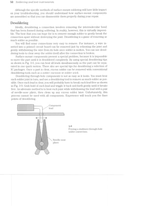
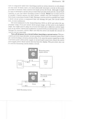
![Mult’i1neters 55
$_
_.v.».¢. . . . . . . .. . .» ..... . -1
4- -:i:
1'3 '$:
5' 33511 ;r 5;» 1
*5 3*-‘8» 4'1"
...$t=....... . ....""".....!..¢I
-:-1-:Q-:4-I->.--5‘-:~:-:»i~>>:-:-:-:+:-1->3-'+: '-:-:-:-'-:-:x:»:x2:-2-:-:4»:-1
§;=:=;=;=*<=:=:€&=;=s=1a=a2=<~'~'=-'~'-'-$:r=?=r==£=s;=s§;=r;=;as
>_..-;;;:-;:Ȥ"-:;.;*'-' - - -
x'"~.
:-33-r-:?:~:f:§§§~:-¥,l - - - 1‘.!:!:1:3:1:T:-:-:/}:1
~=;=;=;=.~'/*=;1:=;'<=; Few ==r==;1.¢;>.'<=;-;==-:->:-1%:-:-.~.~ 1. .*.-.-.- -:<~--:1.-;-:-;-2-:($5-n..... R F A-
M. ,9:-.:-_..$ =. Fr >r
._ ._.___._._...,.,. . . . .— . . . . __.- J__;i;.;.;.;.;.
- -:-:-:-:-'~>:~:-:~. .'. ' . -. ' . ' . ' . ' .' . - .-:->:+>:-:»:-:-:-:
'3"':'$".'.:':.':':':.. .'.'.'.'.'.'.‘.:- .»:5:3:3:.-55:-23%;:;-:.;.;.;.g;;.;-;~ ;>;.g.g.g_;._-.._. . . . . '-}‘.;;:{.':.‘.'4'.-.. 1> .- .. . . .__“
:-‘:15:15'-:3'1:T:?:!$#5:%5:&""‘--_‘- --. .1:'<r-r:=:'-r==rr:I:=.-~£’:=
"§:1:5:*:€i£:1:!:E1:¢:I:§$£e1;f,§§z'xc'%-‘£11:§:$:=§$:I:I:§:!:¢i§:1:1-r’.-1-3;}I-2-l~l-i~I~‘-'<>-.<.-if! /.<.-144;;-5*:-Z62-I>5x-2-H~i{i~Z‘;-.;}¢I-.-2'2
3:3:1:1t,:1*'§',¢:5:1:I§1:?:3:3' ' "'521:1:1:121:21:!:1:i:1:I:¢:i-5:7:-:23:-: "'3: "‘
are ear-¢;=;I== :¢1;a~'¢:;:=r=:*-=1s=:=-a=§;1=>1->1-1-5?»_._~_.+ +,._-_.:.'~_._.,_ ,-_.,. . . . 1 .n . . ..'>.(. - -5:-'¢,~. '-
s==;;:z:==' NIGELSurin 1_e Sstanc ei
it
ter to low resistance scale, then ‘place your test leads across both points to mea-
sure. ldeally, good continuity should be about O £2.
fiiieciring a capacirur
There are two methods of checking a capacitor using your multimeter. lf your
meter has a built-in capacitance checker, all you need to do is select the capacitance
function and set the desired range. You might have to place test probes in parallel
across the capacitor under test, or you might have to remove the capacitor from the
circuit and insert it into special fixture on the meter face. A capacitance checker
will usually display capacitance directly in nucrofarads (uF) or picofarads (pf). As
long as your reading is within the tolerance of the marked value of the capacitor, you
know the part is good.
lf your inultimeter is not equipped with an internal capacitor checker, you could
use the resistance ranges to approximate the quality of a capacitor. This type of check
provides a “quick and dirty” judgment of whether the capacitor is good or bad. The prin-
ciple beliind this is simple--all ohmmeter ranges use an internal battery to supply cur-
rent for the component under test. When that current is supplied to a working capacitor
as shown in Fig. 8-15, it will charge the capacitor. Charge accumulates as the ohmme-
ter is left connected, and can be seen as changing resistance on the ohmmeter display.
,Open
Small value
Medium value
, / / / Large value
. £>' 3:1 i 1
1 Q ;:, , ,1=‘*“-'"~'““
1 _:; ;:;. r:/‘i 3 , ' .1~'
F 1, l /
‘V
J
%
.‘. .>. V 3:
_ Ii ll
iE=-1:1:r==-===§=1=r;s-':r==>==<~==11¢===5='":2:is$1=:I<:'-'1?-s=’='-r=’nu--=11: ‘
1~§$i:IF:7:1;§:]:;:»:!:=:="' .-—-"'1"?--. ‘=15$E1§1:=5¢§$:?:1E1-I:- “
a=:===-<>;==::=$=>3;1'¢'-'-'-"-'1- 9%-:-1-:|.'.‘.‘.'. ' -:~:-'-:-:-:-.:-:
=;:;§=f=:=%g».;r_l'q= '=1~'E'¢:;>.?====;=
" L I Y V. D7 ._._._._._ . . . . . . . .1"-;.~.;~.;_.
=§3£rI~€r:a:r=E- -,.,- ,~1?:~=r=i‘.=‘=1=1=: 1l;§;2;:;‘,;:~1;._f;I§?;!f.4,‘.|'.‘.’.'. . .'.'.'.'| l:;:;:_~:_c;:;:;:;:;._.
:;.g.;;:;:_?:;:;:;:>-4:-;~. 3~ .~.-.'. ".".".' ,e ~!=:;:_1.-‘-:-;~:-:-:~;-;.. ., V 1 1 ' *1_ _ ,. :_.;.., . . . . . . _r-._,_~1;.;-,-,>_-_,. > 1 _‘ . .1 flmpfiqw
W 1 - '3 =1 w->*.-
Ear:=§<=I3=:z<:2:?é%:=:2!QIs:an?;E§3E:=§a,;§:sE1r5§$>%E=§5 Q fill: 3.-1l(_, 6 _i,.¢v-"""'H} ' ' ' ' ' ,- ’ ’ ' ’ ’/' Q1 .,.._,..x_, .. ,_,.__.,} , V, WA
,1, K ear, ‘i»1§a",=,&" ~>>r <,
,.. ., ~.; ,=,..-_. - 1 1 _. .. ..--1-<1-':I,I--:1;i-;i-3:1-;:I-3&5-;:I .-_:I-;:>;:l;:I-:I;:>;:'_;'_.I-;. .' 1-=1.-.-.-:¥:1:1:-‘:15 - 1 .1 1-".-'./.-"._:;.;:-'-. .-§$:;:;:_-:;:;:;:;.-i ;!§-‘»:;:§:;;;:g:g:;:-"E}:1'1c¥'<,->.>:;:-:-~:;'~ - - = _. _ .-‘ -'. .,.. .-wt. .....- . 1'): .‘-_ .. .2~. . .~.~.-..‘.-:-.2- O 5 _ '_ (__,.:_,_(,’,.i_,.:__..__€_.'__|;,__»’_.__.-1,.
1; _- _ _. _»_,_»_.-_,-__.-_,-_,__.-',-_._/ .-' V, _,./, ,1
>111 ' 1 .- .-.-'.-‘,-'/'.-_.- .-_.-1'.-'_.-' 1’ -"W _ .,.
11 .-".-"./'.-'1"-".-“='.-".~".~"/‘.-" -"./ -" -" -' -’ -" -"'
lit; 9 . ’ ’ / ’ .»
ti 1 . » *
1-11. Q - .r .-'3.".P‘.-“.~".-"."'.~".".»'J.»'_/'."'."'.~".-" /7 f / '1 1-"."'.-".-"I-".-“.4-’.-' .1’:-".-"
gr; .' x _ _ _,~1_.-'_.-j_.-',-1_.-,;.-1,.-;_.-;.-1
ti»: 1' ,,:; " / .1 ,-‘.-‘.-'.-".-'_-1.‘-/'.»'.-'.-*.-_.-"_-
1i; 1 < .- ./.».-'.-/ .»'_.- .-‘»'.- /»'x.-_.»‘,- .-., V .,.-,.- _1 _.'_.'_.-_2 ,'_.‘,: _/ _.'_.-_.'_.- _.- _.-’.-_. t, / _.'_/ _.-_,.~).- _.-_,,-_.-,.- 3, _. /~’:_
. J ,
1‘2’
5 /1.-.'.'v-.~.'.-.-.-.':~.-.'.~. I - - - I - - - - ¢ u | I ¢ 1 | > v" I‘ n".-"-4‘{|"."n"'~"_-' 1‘. F‘-‘fl -'
- ,1 1 _.~_.' .- .~_.-_.* _a _.-_.- _.-_.- ,' .-_.- .- _.- .-'.- I ,1 :_.-_.-_.~_.- .-‘; ,.~ .»_.' .- .- .- .-
£:u.fl .€'1:1'.'~v-,.~ :-'V- g--.4-1.-‘¢.. “1k1‘1l1'Yl n:...r-. '1-:.~.-1.‘.-.1-'-1<~ - 1*?"-'01 rm-1.1¢n -.1~rv-w1‘11.--.‘11-‘-1>1--.
. lime
C5Ll3?1Cill~O1‘ Resistance readings versus
time
3-l5 Measuring capacitance with an ohmmeter.](https://image.slidesharecdn.com/ozgdplurrtdj8c4ktjrb-signature-f36449d24fae8f28749ba408629a60e09bfd643da03035012a2b233e7710df3e-poli-180806114914/85/Easy-laser-printer-maintenance-and-repair-61-320.jpg)
![56 SOlCi€’)"“'2;’iZ_C] CL’i'ZCZ test mstr'tm2,e'2rzts
When first connected across an ohmmeter, the capacitor will draw a relatively
large amount of current——this indicates low resistance. As the capacitor charges, it
draws less an.d less current, so resistance appears to increase. Ideally, a fully charged
capacitor draws no current, so your resistance reading should climb to infinity. When
a capacitor behaves this way, it is probably good.
Understand that you are not actually measuring resistance or capacitance here,
but only the profile of the charging characteristic of a capacitor. If the capacitor is
extremely small, or is open circuited, it will not charge substantially, so it will in-
stantly read infinity. if a capacitor is partially (or totally) short~circuited, it will not
hold a charge, so you might read zero ohms (or resistance can climb to some level
below infinity and remain there). in either case, the capacitor is probably defective.
lf you doubt your readings, check several other capacitors of the same value and
compare readings. Be sure to make this test on a moderate to high resistance scale.
A low resistance scale can charge to infinity too quickly for a clear reading.
seiniconduernr ciiecirs
Many multimeters offer a semiconductor junction checker for diodes and tran-
sistors. Meters equipped with a diode range in their resistance function can be used
to measure the static resistance of most common diodes in their forward or reverse-
biased conditions as shown in Fig.
. Set multimeter to a
diode resistance scale
ii to ensure best--1 I'-
D@1'1’O1‘111a11C@-:-:-:-:-:-:-1-:-:-:‘.~:':-:-:-:-:-:-:~:-:-:-:-:-:-:-:¢~:-:-:':-:»:-:-:-:-.-.-. . ..._:-<.s..‘,.-.....:¥5_.|i. _;£"-=.--..-...
.;I;._I;-;I;._Z;Z;1;I;.;§;Z;i;Z;i-' ' _....-I--n.._r ' '~I;I;Z;I;I;I;I;I;1;I;I; _‘;
=I=I-III-1-I-I'Z-I-Z=-f-K-3-' .1-'.'.'.'.'. 1". '-Z'I=I-I-I-I-I-I~ZZ-I’?
.;.;.;.-.;.;.;.;.;.f'|~ . . . . . . . . .-I‘[..;.;.;.;..;.;.;.;.;.;.;
" ~ 2:1:!:i:=:!:i:i:= ~I:1:1:1.-:1":!:1:= ,1
§;I'§;§;Z}Z;§:I' '='.'. 1 I. . - - ':'§'§'I:§'i'l§'IjI: ii
- -_-:-_-_,_-_-_-:1‘. §¢ - - ¢ 'l_-'- - - u 1 ‘_v:~:u:»:¢:-:.:._-h
" --. :':'I'I;I;Z;§::;§;.qiI'.'.'.'.' . ' . '.'.'.l iy-!'!~Z~!-I-1-1;:-I-Ir 1
_-:1:-Q-:-:|:|_-_-'-‘:3, ‘; a ¢ 1 | . - - -1' -3-:-:-:.:-:-I-:-:»:;
-:-:-:-:-:-:-:<-;.:..~;-1:3: » - - - - -' -..-.-.-.~.~.-.-.-.-.-.-.*§'.'. '9. ' .. ' . ' . ' . '_,_I%'Z-I-I-2-Z-Z-2-I-Z-I-2*....... --..-... _ IIIIIII ..-.... . . . . . .... . . . i. . . . - . .'§~.'-'-'.*.'.'.'.*.."v' "'-L=-L -*.'.'.'.'-'.'.'C'.'.'. . ._...-..--U"...-...-vi. .@~....,............Illlllilllillllllll .,,. -P "..- .---........_.
' -5-1-1'2-H-Z~Z*2~2-2-!-1'!-2-E-I-I-I-I-.-.‘*“."."."'*’..-.=Z-1-I4'1-3-3-f-I~I-I-I-I-I-I-I-I-.-1 ---nun-H"..-."-1Inu.“-“....5..-"---u
i -'-*-'.'q.~.'.*.'.~.-.'.-.'.-.-.;.-..-.‘-'.'-'.~.'.'.'.'.-.'.'.'.'.-.-.-.-.. .'.;-;.=.*-'-'-'.
I ~I'I'§'I' i ' "I-1-1-7;:-I'I'I'I'‘Ii"'1'1‘I'1=§'§'Z'Z'Z'§'1-1'I-3-I-I-5*!-C-.".'§~I'Z'§'I' 'i .7 ;.g..g.- 1-.;.;._.;.;.;.;.+ +.3.1.3.';.;.;..;.§.;.;.;.;.;.3.;.;.;.;.;.;.;.;.;.;.;..;1 -.. ........| |..................---H...._-_.‘ . _._._-_-,-_-_-_+ +_.,._.,._._._._._._. . . - - - -_._._._._.,-_.,._._..... IIIIIIII “..-... ..............- IIIIIIIOI ......... "..-".... . .. . . . . .5 .=.;.;.;.; ;..;.;..:I:I;I;I;I;l:I;I _ I;Z;Z;§;!;Z;I;I;I;i a I'1'§*Z'§'§'I'Z'§~I~I i_ 3% 6
r Performing a diode check.
Forward check1..sf‘: ii>;i=.».,¢,555$ ?~‘l5Fi‘JI 2"-'-1. .
=.=ii.'i='s‘;‘_-‘>!':";=.~.
‘E~,v~,i ~“'» -
-‘ ~ - -'<-“i.-.i?L‘:i1~:'=‘;‘-‘.~=.=.mi;:s:m=::=-F-:11?, ,
a
_ / Reverse check
"'|"i W :!'.','.' i—».-.-.~-.u»~.>.'-my: I‘ '
- '-:*»i=.:!&i:-= "'
=<.!.>."<1
J.i 1‘-2‘
Select the diode range from your meter resistance function and place test leads
across the diode in the forward direction. A working silicon diode should exhibit a re-
sistance between about 450 and 700 Q that will read directly on your meter. Reverse
your test leads to reverse-bias the diode. Because a working diode should not con-
duct at all in the reverse direction, you should read infinite resistance.](https://image.slidesharecdn.com/ozgdplurrtdj8c4ktjrb-signature-f36449d24fae8f28749ba408629a60e09bfd643da03035012a2b233e7710df3e-poli-180806114914/85/Easy-laser-printer-maintenance-and-repair-62-320.jpg)
![IV] 'Z,LLZ'L'7’)'?/8Z8‘VS 5 /
A shorted diode will exhibit a very low resistance in the forward and reverse-bias
directions. This symptom indicates a shorted semiconductor junction. Be certain
that at least one of the two diode leads is removed from the circuit before testing.
This will prevent its interconnections with other components from causing a faulty
reading. An opened diode will exhibit very high resistance (usually infinity) in both
its forward and reverse directions. in this case, the semiconductor junction is open-
circuited. lf you feel unsure how to interpret your measurements, test several other
comparable diodes and compare readings.
Transistors can be checked in several ways. Some multimeters feature a built-in
transistor checker that measures transistor gain (or it1,6) directly. lf your meter offers
a transistor checker, insert your transistor into the test fixture on the meter face in
its correct lead orientation (emitter, base, and collector). l/la1nifacturei"s specifica-
tions can tell you whether a gain reading is correct for a particular part. A low (or
zero) reading indicates a shorted transistor, and a high (or infinite) reading suggests
an open-circuited transistor.
Your meters diode checking feature also can be used to check a bipolar transis-
tor base-emitter and base-collector junctions as shown in Fig. 3-17. Each junction
acts just like a diode junction. Test one junction at a time. Set your multimeter to its
diode range, then place its test leads across the base-collector junction. lf your tran-
sistor is NPN, place the positive test lead at the base. This arrangement should for-
ward bias the base~collector junction and cause a normal amount of diode resistance.
Reverse your test leads across the base-collector junction. The transistor should now
be reverse-biased and show infinite resistance. Repeat this procedure for the base-
emitter junction.
v I
j Set multimeter to a diode
ii;:-:~:-:-:-.'~:-:-:~:-:-:-:-:~:-:-:->:-.-:-:-i:-:-:~:-:-:-:-:4-rc-.~:-:-:-:-:-:-:-:55; e S S 8 C e S C e tO € 1.e
best performance
:‘-:12}:-$:1:11$:i:=$,*h-:;:-:¢:-:1E~:-:~:;:;:;g:;:-2?:-:-:;:. :-:-:/,:~:-:-s:-ac-:-:
:?:1:~:1:?:¢§:~:3:1'1:-*2'F:~$:1:¥:3'1:1-H1-H-"'31-2?:-:1-?:§='!¢=:!:1:!:?:¢:;1:1:
'-"‘:‘.'-'''-'-5 I’-'»" '-' "-‘-.-‘" "~'-N‘-‘o"v4-'v"‘i'-‘-"R4---.---V.-vi an - . .-r. ....,......... i
§:;:§$:3§:§:§q:§:§§:,' ‘.1’.'.' .'.'. ' . "E-.' "3:§;,¢:§:=:‘=:i$:§:=I§ri 1.-‘)’:-‘lug’ '0-1,‘ _ I o I 0 u I 0 0 I ‘ ,sI:uj~:I:o;:u,l: 1
;:-:;:;§:§‘:-,:‘;‘§;:E;;;:~§' I .' .'.‘. ' .'.' .' .'. ‘I 5?:;:§:;:;:-:;:;:;;;:; i
<31:-:-:-:-:~:-:-:¢-' .'.'.',-4-;.'.'.".' '-:1:-:-:3:-:;:-:-:-I
1:-:4-'-:-:-:-:-c»:-'¢ 13:3:-:¢:-:=:¥:=;.;¢;§‘;s;.;¢;»[-'-_ - | - . I ~ ~ ;_.$.'<:.¢.;.;.-
. -:-:-:-.-:-:-:~>:-:1*:- -.'.'.'."| .-:-:-.-:;.-:-:-:;:. -.-.--.-<-up.-.~.-.4 . . . . . . . . )~.~-.-,;..;.;.-.'.-
i :-=-'3'-w '-*-11.: I, . - - . - - . -j ;-',-3-,-' -,-3-_-3 .. . .....___..__
3 -:1:!:I:=:I'=?-'r?:='-:=q§' I fig:-'-:-"ii:-:-'-~.,,..~aa'...~..fi . .....~,..-sq.
1 -».=:1:=:=:§:1:¥:¢:§:=;-*¢:-., -J.-‘-‘~'-'»..1"' .-:=$:=:Y:1:=:¥'.F:=:1:5:-:“ -'v'o'-‘-5 "'5'. I"-‘v -'-~ -';-J-JP“ ¢'.‘.'.'.'.'r‘v“-"-'-‘-'-5';l‘ ‘:_...... _-1...‘-<::.:':,:_ ;{::,.:',:,,.:---.-. _
‘a :-:=31EI’=I<Z§:=?E=3=E=:=EE~$:€-:1:$*v='"...-.-.-35-:-E-E451‘-$E-1E==-Eris?%E=E I F .. . i.-:-:-:-zit-'~:-1-:-'-:-:~:--'-ow:-:-:-:-:1:-:-:-:»>:»:-:-:-:-:&-:-=:-:1:--$:-:i:-:- 1 ‘ Q V O (-3 Q
'¢=.=' '<:£=,;=K=.i=+¥s.=;.==.i=.;=;.a=.=:=:=$.:.=s1:=:i=. i J ~ ' ‘9'}. .--~*-1'.;.-3 5-.-Q.-9--e.~.-.-.-',-.-Z§,-.~.--I~Z~1i'-,'
-:=:>.- . -:=:=:=:=:="~2=.+ +:=.F;-:='.'<1:=:=:=:=:=~=:k=:=:-'=:¥:¢:='=:=:=:=:= -
=:=:=:=:‘-: :=:Y:=:=.¢:=:=5:=~;-'=:=:2=r==§:z=s~='viz:=$==t;=:=-=:=2=-=:=;=:= j to Che Ck P t1~cLnS1StOl~¢;__._...___ _ _7 ¢ 1 (, , _
G . _..
Con€C1.O1. (NPN transistor)
2 '-3%‘, ’
Base
_ (PNP transistor)
Base
Emitter
3»-i7 Performing a transistor check.](https://image.slidesharecdn.com/ozgdplurrtdj8c4ktjrb-signature-f36449d24fae8f28749ba408629a60e09bfd643da03035012a2b233e7710df3e-poli-180806114914/85/Easy-laser-printer-maintenance-and-repair-63-320.jpg)
![C) 6 O O LCL€‘}"'L"? Lg CL? LCL L83Z Z-'}°LS ['I"’Ll.-'N'L€'l 21f/S
lf your transistor is PNP, your test lead placement must be reversed. For exam-
ple, a forward-biased junction in an NPll transistor is reverse-biased in a PNP tran-
sistor. You can refer to manufacturers specification sheets to determine which leads
in the transistor are the base, emitter, and collector.
As a final check, measure the resistance from emitter to collector. Note that you
should read infinite resistance in both directions. Although this is not a diode junc-
tion, short circuits can develop during a transistor failure that might not appear
across normal junctions. Replace any diode with an open or shorted junction, or a
short from emitter to collector.
*1 » - »- .. '1
‘:35? <5 “ii "an “-i‘ tit F1»in .~ >:= -E; ,1 ~<, 5:, ';'= - F,-,5
;<=:- i =-¢. ~‘- ,2’ r-4-. A"
1:
The problem with most multimeters is that they do not work well with digital
logic circuits. A multimeter can certainly measure whether a logic voltage is on or
off, but if that logic level changes quickly, a dc voltmeter function cannot track it
properly. Logic probes provide a fast and easy means of detecting steady-state or al-
ternating logic levels. Some logic probes can detect logic pulses faster than 50 MHZ.
Logic probes are rather simple-looking devices as shown in Fig. 3-18. A probe
can be powered from its own internal battery, or from the circuit under test. Oon-
nect the probe ground lead to convenient circuit ground. lf a probe is powered
from the circuit under test, attach its power lead to a logic supply voltage in the
circuit. A small panel on the probe body holds several LED indicators and a switch
that allows the probe to work with two common logic families: TTL (transistor-
transistor logic) and CMOS (coinplementary metal-oxide semiconductor). You
might find TTL and C-MOS devices mixed into the same circuit, but one family will
usually dominate.
.. ~_~§’.1," ' 5' '1
- W1» - -. - .‘*-‘é;7":=;.% ‘ “
- --. » A 4'-'c'.§‘-( Wm
.. t- -wmwQ%w
1-_;;,§5,§,.,g¢ u ' -, ~. was '¢.:;$;-,4$':t- ’:’<-
, _, "- '-'-';:1;;;*.<?¥§?'¢*‘2~_(/
..§»i-.<.»‘1'=r~>‘:='~'e' .1? 1»,-5;.--j='5:» ;:_-;-,-;71;: :;_=-.-- = , , 1,. jq‘}z(,_:_=§i . , ~~‘<i&~_ -,&‘-sue
ah -re-1=-1*“-.>;<<<>‘"~s. *'<=‘<=$“"-*’-lwi.i$ (S ‘r.<§~;>» Q ~ "¢~.~.</.';¢,
" .3 ’.'.'.-;_--.i;1,i>,:z:--,-r=;$;.;:.:‘3;:._gzz.}}:;-:1;'::§,y$*-'-"'-< (Q '1 .; ,.9¢.?-‘='~;Q=,-- _»~,;_,-;_ ,, - ,_-:_._;_1,_,,< ".('§(g(x ' ;.
i3:=ii5.{r:{."I::i»I;1'-1-i-.'IE-Iii-15.1‘:-‘.$55':";%*;3‘ v" ' 'i*§$.»,:'1:.-'1.;::}_:;"‘-§.;’» . _ "iv ~ .. ~»_- .;. _L fig,“ . -,
~ in his’»l:{}3;;_:;_};{~’.3:’;‘_Z"§1v1'.'-3:5:.!~§| Q >"':+{'%"<’§'i;‘?~'§";'
“.. '.v§ ‘ =11125355.},-;_:1,j.'.112;,' 9;‘ c<.;‘,j._;-‘ 1;-.‘~$;= >»»-;:,».,;-;_;>-,____ j. _
-‘T’555EiE3£=E5.5»i=1»=I1"-‘TX.' *.-" "‘5‘ 7* ‘- ' ~"‘~‘§1‘“<§:-*!~’<§% ‘ '{ a;‘§%f)e,w . ‘S,.,.,‘,,.,,v.v,v_:,:s‘ __ ,.,/I
4-/» Q. $1,
" "<'r:- » 5. -is‘-a,-_ cg.’--,-,‘§/‘ ';;_;.i( ,_ '_ A' : ' »'-';,;;.;;,._H ‘ -_.,
j»§:1r§~:’;?}§:{=§5tI;:;1:,:,-,::};.,/>_,‘_ ;§§§}§Q$€_.;:;;;,-;@;._. wqkqvi ark,»
2' '-‘£=:I:'=.‘i1Z1I"-i":I:1'"/.":1;.' ~;,1."" ¢>~-‘- rain ., V; .-,, ' 5;.‘ -, '-=:=i1:=» V "
is~~~<ueua’ r»aea@s
Z
< i
in 5‘
.:Q}‘}"'
>'-'=g.;‘»:;:-:g;;.;,1»;-i:-_;->;.=.:=;.} -- ~,. 2 .|?~ " . ,.;;- i~ ‘X,-,
~' ‘*-1f5;:,:;z§.:}'5.¢:.z:i'*»$';:;._ - ..»"~: 3* ~ ' : _%'." w ":'».;.-j:-;, ‘ = . '-
"===z¥;.12::>a:;11:::111:5».xz - »‘T' ~’ %”"1-..'-:1»-.=";:?-:1:->1.-:»;..»;:.@=»., ~,. ~=- ,.,§>:;<$~Q:;~’_;',i=:&=>,_<,._._<- _.~'i;.-,.=-__ -- . 3,
' ~ ‘Q":-5<>:I;=:r-';'=;»».:;;---. -c. "~ . . an .-»_<_=;<-,'-1~ a;¢.si. », ":1>I'1- > --.
"II’%E%?:?ia‘£=;’.i&E’::1£’?131:=... “."1‘<ié:.:; ‘ » “*=*»'£:5>2:IIEFTI1‘3;T§£3JT§IT§,Z3.313I251?'='»i':1:r=-.-.-,,..
*anaauananwwwa~iweee sanwsnreaaa»"“k’iii").?'".~‘1_f;};2§5:;",:‘@‘ ._,._-=>- =._; : --i.~'-I-is.» 1 .. - =~=-» 11:.».3. , a,§§.‘%§,<=~:_§,:,,§<,_a-=;:‘.=.;“?j-<~"§ I-={*é.‘ir3l.-.i..,,§.F {H ~,a/ gi. -.‘vi "-<=‘}..=;-.-.g.=I. Y?“-‘=-‘:I."';§T<-‘J~’—l]$-‘— , »;-11:2 ‘-EL‘? -)9.'='§¥>1 -‘,,;,:_
~ riser:-"=-I. 1-.;<:>_,~ .=1.;i,* ~ '
"1:§§~= r - ix _/'—* » v" .¢,.. .
'- * s
-'12:£:2.;:r:z-1.I:§>:’E-l*3=.;». . .,-.. fl»-i<F" "‘”-“"*‘l"'~'"- 71?"-1'“ -"‘ '
73:45“ ».é"P:§n?%=~5§4:-12¢:ai:¢$2»:€a~!§k»:ei&3s$sEi:$.gi§{§r¢.- ,~.;'/- i-.95‘
»-:1 -- 0
2 5?»
J‘
5%’ » '51 rfis kw S’
,. K Va
v% r;i‘is?2%-if, 'r*f>¢i';,_ ~"5:?s%‘§iYf;. '-.3/4.: .-_ ;:.;._2;- _,_ , .- _, -1-~-;-‘=: 1-v-.~i;K;<-1-.-2 --1-=.~:-: rt>.':; __."v'>:1:¢<§ '5' - -3151;‘ : ; X?-:-1-E12-:;.‘ .;;:;:;;;£$;£"ii:_g?;;gE;I’-5515;‘ .1: >3;
I
-. <".’~',. -.1‘1i1_;;.r..._ .._.:;";;I<:;'.j->£F >_:;;»;=;.;s=,
'='-»~I¢:€:i=;-.5II»r:EI-’-‘J51;-1. i?§T;.~§:‘;'=:L*w.j¢I:§J;X%'-‘ “ _4§§§Q( ' ,,_.;.;.,¢;:;»E5;;;1;;1;;<§£9 ,.-:H;1;11:'¢'-:
.
‘ ' ' '-: M-I-,'i"<'7+.1§'-~‘i“i'T-_~_; :Z‘Y '-' - " -. -=- -31'» 1»;-I;-'.-. ,wsii--S5:>11;2Ii:11-.5,£35»;5:;1;I;;:=-:-;::=» ~'j.;_.;.:-5.-:'-';'x>;_. r ..¢-$5§,;gg._.,.1:g;g.;;;=;r;-»'~‘= . _~3;»-;
-». =11-’:»>'<=:-»‘»:=:»:’i€"w§=:"=F3"-t9“i¥‘=-55°-7“ Q’ -‘-=:{*‘*3 '- » - . -t-'==.~:;:¢=:;-=:l:1:r,;~»=.-».-.~. , , . .:..;-,-1,--.--éi~ .--an:->=2-:<-i;-;-;-;-ator ‘-.-.¢,».»_ -r
.--. i-<:f~'.=I~.':- ' ,.-'-,.," ah -.5511-.<,~. -?:e>‘=*-"- -‘ :1;-1--.. , - .. -"-1'-'* .¢.,.,:=:,;i;-.-.-13131511:$21:3;-=_>:;;;;¢¢~a;"- . - -
‘M215155:112:21-'»"5I?f< sf: , ‘($2, §%‘§N.§4;;>2-'1.-i:<».;.,;..,E_I_.;.;;.gI5¢j-.=;1-='-=1§?§<- ,,..f_':;>,:-5.-;;11>‘:_’"
‘*4-“‘! =<i1*=-1* " ’w~:;-;1-::'»;»:":-'~--' %¢‘»*'-¢§-iii-5=~‘=4§~?@i'¢2?»xs%-=.§*'T*r;~=$ ' -:‘ B Wis:-';r>’:’:‘.-l‘¢;>'-'>'-%?*-=<»-M.. . .-;<».»>=s:.:=.1==;-rear:-rfi/‘+’¥?:'
. ri-.;:>.s-'1-':1=-i~$}'s‘-~'+§»' <‘{'>.>»'~>:='»=&'<§- "-"~" .¢i{¥=-4:..-1'r:*» :1»:--1-».:;—r—.=:¢"-.<>.—;.>@>~ ‘ ->.»;q-
‘ >1-2:-:"E*’.»'.’--‘I 5‘:-s/5g'q_‘-."§’),.:,'¢§§<-f+,‘~§'¢€.>.'<”'-'’§=¢' .;<;Q',vi~j;_,; .» .. ‘""~=*¢~1~1:>-.~:5;i,-5ii.1;.,: ;..;i:,;.-s.».=-si;==a¢%*"" ',
‘»’v‘ii§'r W $53’-ire 2-; .=.=¥=_ -2‘-QIQ‘,
Tribe, ~' ~ " >f<~Yiii<1‘ ~‘- ..=P1'>5*¥i1W=§*4.*§$=&<" ' --:ir'£-1 1'15-E5-1:7
*.'S’3~. . - -A==“§‘§t55l ““1§;%$r¢3-¥ii"@=5'*7‘=!5l§?¥$“ .. i—~?$>‘ii‘i is-";:;"-"F
' .. -—;»~s.-'-=.=:"§:=-.'i‘=-.-F22-3§~»'i _- ,;:1.~;:*'> - .;1Wi, . §~x'_L .; .~2{=‘~vFx.-i=l.-~.~1'-:¢<
"! . . - d- - . X I)
i,-=<:..~:l ~ ‘-‘ i -~=>. >1-;.->.<
'9 fliiirk ‘ .'~.-2:;-;=:-5' ' jgfim; 1r - . ,_ -‘I:-.1¢.,,,_
Y‘ '7;§§-,_ ' . -.-=i.=:¢5§>‘;_ (1%-“"35-i"‘-‘ii-.<>:=
<¢*§:"=- . -'1; 1' ';;:'¢.':Li ~'<‘34:{»‘§§§= :_=;* v»
/Q, r »
Qinarfin wanes -i/‘S,/_ .'_lZ, _ _
Of) -. ~ --.~
3-i8 A B+K DP-51 50 MHZ logic probe.](https://image.slidesharecdn.com/ozgdplurrtdj8c4ktjrb-signature-f36449d24fae8f28749ba408629a60e09bfd643da03035012a2b233e7710df3e-poli-180806114914/85/Easy-laser-printer-maintenance-and-repair-64-320.jpg)
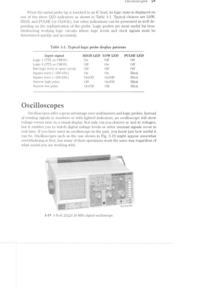
![Oscilloscopes 61
A time base (or sweep range) specification represents the minimum to maxi-
mum time base rates that an oscilloscope can produce, and the number of incre-
ments that are available. A range of 0.1 us/DIV (microseconds per division) to 0.2
s/DIV in 20 steps is not unusual. You will typically find more time-base increments
than sensitivity increments.
You must observe a maximum voltage input that can be applied to an oscillo~
scope input. A maximum voltage input of 400 V (dc or peak ac) is common for most
basic models, but more sophisticated models can accept inputs better than 1,000 V.
An oscilloscope input will present a load to whatever circuit or component it is
placed across. This characteristic is called tn];>tz..t impcctcmce, and is usually ex-
pressed as a value of resistance and capacitance. To guarantee proper operation over
the entire bandwidth of a model, select a probe with load characteristics to those of
the oscilloscope. l/lost oscilloscopes have an input impedance of l MQ with l0 to 50
pl?‘ of capacitance.
The accuracy of an oscilloscope represents the vertical and horizontal accuracy
of the final CRT (cathode ray tube) display. ln general, oscilloscopes are not as ac~
curate as dedicated voltage or frequency meters. A typical model can provide 13%
accuracy, so a l V measurement can be displayed between 0.97 V to 1.08 V. Keep in
mind that this does not consider human errors in reading the CRT marks (or gr/*cttic—
tiles). However, because the strength of an oscilloscope is its ability to display com~
plex and fast signals graphically, 3% accuracy is usually adequate.
fiscilioscope startup procedures
Before you begin taking measurements, get a clear stable trace (if not already
visible). lf a trace is not visible, make sure that any CRT screen storage modes are
off, and that intensity is turned up at least 50%. Set triggering to its automatic mode
and adjust the horizontal and vertical offset controls to the center of their ranges. Be
sure to select an internal trigger source, then adjust the trigger level until a trace is
visible. Vary your vertical offset if necessary to center the trace across the CRT.
if a trace is not yet visible, use the beam finder to reveal its location. A beam
finder simply compresses the vertical and horizontal ranges. The compression forces
a trace onto the display and gives you a rough idea of its relative position. After your
trace is moved into position, adjust your focus and intensity controls to obtain a
crisp, sharp trace. Keep intensity as low as possible to improve display accuracy, and
preserve phosphors in the CRT.
Your oscilloscope probe must be calibrated before use. Calibration is a quick and
straightforward operation that requires only a low-amplitude, low-frequency square
wave. Many models have a built-in calibration signal generator (a l kHz, 300 mV
square wave with a 50% duty cycle). Attach your probe to the desired input jack,
then place it across the calibration signal. Adjust your horizontal (TIME/DIV) and
vertical (VOLTS/DIV) controls so that one or two complete cycles are clearly shown
on the CRT.
Observe the characteristics of your test signal as shown in Fig. 3-20. If the
square wave corners appear rounded, there might not be enough probe capacitance
(Cprobe). Spiked square wave corners suggest too much capacitance in the probe.
Either way, the scope and probe are not matched properly. You must adjust the](https://image.slidesharecdn.com/ozgdplurrtdj8c4ktjrb-signature-f36449d24fae8f28749ba408629a60e09bfd643da03035012a2b233e7710df3e-poli-180806114914/85/Easy-laser-printer-maintenance-and-repair-67-320.jpg)
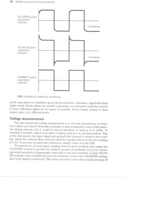
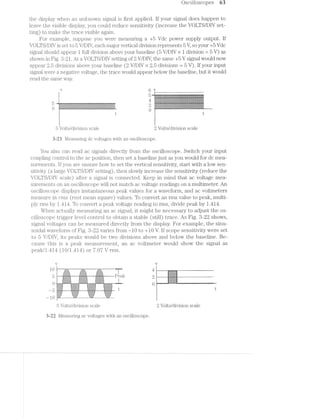
![64 Soldermg Cfil/I}/2/(TL test mst'2"'2.tme/ms
Time and irequeney measurements
An oscilloscope is perfect for measuring critical signal parameters such as pulse
width, duty cycle, and frequency. The horizontal sensitivity (TIME/DIV) control
comes into play with time and frequency measurements. Before making any mea-
surements, you must first obtain a clear baseline as you would for voltage measure-
ments. When a baseline is established and a signal is connected, adjust the TIME/DIV
control to display one or two complete cycles of the signal.
Figure 3-23 shows two typical period measurements. With VOLTS/DIV set to
5 ms/DIV, the sinusoidal waveform repeats every 2 divisions. This wave represents a
period of 10 ms (5 ms/DlV >< 2 divisions). Because frequency is the simple reciprocal
of the period, you can calculate frequency directly from period. A period of 10 ms
represents frequency of 100 Hz (1/10 ms). This process also works for square
waves and other waveforms that are not sinusoidal. The square wave in Fig. 3-23 re-
peats every 4 divisions. At a Tll/1E/DIV setting of 1 ms/DIV, its period is 4 ms. This pe-
riod corresponds to a frequency of 250 Hz.
5 ms/div 1 ms/div
v v
1 0 W H V W V 7.4, -f:;:;.;:;:'| _.;:;:§;._ 4 ‘‘-'1-“‘:‘.l-“EVA-LHR l I -.f,}rivF-11%;‘!-.-, e.~.,.==.~_
_-,~_-;-_.-| _~'.;.;a,.~._ _.;.;.j-,;._ 5: ._._._._._-<_.__~_. L; it . _._ _.,., 4- H
-$:¥:=>‘.=§: <€r»<;=?-;- -2=;=;=r-;==- .<:1;1:=.<=€=:=-=-'<= 11.: $;¥>'>t”-:1:=.<;=3- i
¢%;¥:1:1$*1:¥. :1$:¢:1'1'I:¢:3‘ :1:1:1‘5:I:='1'7' '7'i'?'=°'%1’J31$ '3‘; iif’ 1 ~~. <.-. -.;.-.-:-.-.‘:-:-:- '-:A:<:-:~:-,-.-:~:~.- .>' ii .»(.~.-:<;._. _,-.- =1.3 I‘ . . _ ... --....... F . .. .... .. >_, :3-.;»;.;.;.;.;.;.;.; ii .;.;.;.;.;>._.;_.;>; 1,
r 1 -'~'.'-'~,.-.~.'-‘re .-.~.._.-.1».-. .-.-..-.;,-.-.-.~. , - rs "‘" ;-‘ J. " "“' ii. ~;-_;.;--';~r_~v'-; .;.;~(.;.,-;-_ 1; 1. ;._.;.-,;,;._._»;.;.;. L: __-_._._._ '1 vi ._.,._ . .__._._ t
»:~2r:'<;¢i%=;22= z i ==r=if;=>r=~,=§=:= 1 :===;=3=2=:=>'>';=== 1
:==>.=:=:>?-£=s::;éia :=:=5=:=E=a=~5$E=£=;= = 1¢5r=r=>.-;==;¢»a< ii :5;=:=§==1>'-,.5=-&=§~.~.--.__-._ - 3.; .3-;.;.;.;.;-~; .;.; .1--.;.;2_.g. , ;; .-.;.;.;.;._~.;. .-1' 11. 1:; ._ .-._.;. ,4: =;
0 -:k$:¢:@:$§=:~:1 _:;:-:-:»:‘:~7$§-*1:~:-“ :3$a¢'-:1:-'7?-:l$:=‘ _ _V_‘__ __"W :3:-¢--:—':§=::¥’5;,“ “M ‘I :-?1;lE—>"~:€-;~'¥-' _v
ti:-.~:-.~:~:-:4 §;i:§:1:5:5:7:§.<:f:=:¢: ':?'2*?%:=:=:?:'“ ' ' ' ‘ '. _ . .. ._. . _$~_:,“._ l ‘ I I I t
Q >
3’ )' J‘.
w > /
, , -. | ,. ---.<--u P4 -'-‘-‘-'-'.' 2'-‘nu
i:i:1:-:i:¥'-:-:1 . ':».I:1:1:1:1 $:3:=:1:-':?:?'f:t1:¥: '1-3'1:-EI~I‘§:I'!'I'1:I-5-‘~!2<2-F -: '-:-:-¢:~:--._,-:-' :-*<:-:-:-::,-:-:T:- -:¢:§;-'-:Y:Y:~:?:!$:~ 4
-1,}.-N ',-1-A ._,-.. "..- um. <.... -.'..-
:;!;.;Z;I;!-:;* . I .—' 1&2-I '-1-..~!-Z ‘ :-15:;-153+!-:-2 3.1.3.1.-:.:.g.3.;.g.g
-.-:-*-:-.~:*:-'-:1: WW -:-.‘.-:-'.->:¢-r- W ;:-:-:-:+:-:~:-:-:~
;:-,;,1:;._._: ~.~.~:-:~. :~. :-: :~:~ --—~ 5
=1?==€=E* ‘$515151 '¢I<E:E=3='
— 10 F ‘*-wk-*'W,
10 ms A I100 Hz 4 ms = 250 Hz
5 ms/division scale 1 ms/division scale
3-23 Measuring timing with an oscilloscope.
Instead of measuring the entire period of a pulse cycle, you also can read the
time between any two points of interest. For the square wave in Fig. 3-23, you could
read its pulse width to be 1 ms. You also could read the low portion of the cycle as a
pulse width of 8 ms (added together for its total period of 4 ms). A signal duty cycle
is simply the ratio of a signal ON time to its total period expressed as a percentage.
For example, a square wave on for 2 ms and off for 2 ms would have a duty cycle of
50% [2 ms/(2 ms + 2 ms) X 100%). For an on time of 1 ms and an off time of 8 ms, its
duty cycle would be 25% [1 ms/(1 ms + 3 ms) >< 100%]. Use caution in duty-eyele
measurements.](https://image.slidesharecdn.com/ozgdplurrtdj8c4ktjrb-signature-f36449d24fae8f28749ba408629a60e09bfd643da03035012a2b233e7710df3e-poli-180806114914/85/Easy-laser-printer-maintenance-and-repair-70-320.jpg)
![T/te troublesh.o0t'mg cycle 67
Another test is to try a working printer on your computer system. As before, you
might need to select another printer driver to operate the working printer properly
on your existing system. lf another printer works properly, it verifies that the coin-
puter, software configuration, and cable are intact. If a working printer fails to work
on your system, check the computer communication interface, software settings,
and interconnecting cable. Complete this check in addition to testing your question-
able printer on another system.
When you are confident that the printer is at fault, you can begin to identify any
possible problem areas. Start at the subsection level. You might recall from chapter l
that a laser printer consists of several major subsections. Your printer fault will be lo-
cated in at least one of these subsections or suba.ssemblies. The troubleshooting pro-
cedures of chapters 6 through 9 will aid you in deciding which subsections are at fault.
Once you have identified a potential problem, you can begin the actual repair process.
ln many cases, your repair will involve replacing a defective subassembly. For skilled
technicians, the repair might include tracking a defect to the component level.
Repair or repiaee
Once you have an understanding of what is wrong and where to look, you might
begin the actual repair procedures that you think will correct the symptoms. Some
procedures require only simple adjustments or cleaning, and others might require
the exchange of electrical or mechanical parts. All procedures are important and
should be foiiowed very carefuiiy.
Parts are usually classified as CO’fl2]30’i‘Z€'lZl§S or subcrssemblrles. A component part
is the smallest possible individual part that you can work with. Components can serve
many different purposes in a printer. Resistors, capacitors, gears, belts, motors, and in-
tegrated circuits are just a few types of component parts. Usually, components contain
no serviceable parts—the components themselves must be replaced. A subassembly is
composed of a variety of individual components. Unlike components, a complete sub-
assembly serves a single, specific purpose in a printer, but it too can be repaired by lo-
cating and replacing any faulty components. Repairing a defective subassembly simply
by instalbng a new one in the printer is certainly an acceptable solution.
All technicians must make the cost/performance tradeoff when performing a re-
pair. Component parts are much less expensive than subassemblies, but components
are often specialized and can be difficult to get. You also might need test equipment
and time to troubleshoot to the component level. Replacing subassemblies is faster
and easier than tracing component faults, even though assemblies are more expen-
sive. Subassembly service makes good sense for individuals who lack the time, expe-
rience, or test equipment to worry about component-level faults.
Replacement electronic components might often be purchased from several dif-
ferent sources, but keep in mind that many mechanical parts and fittings might only
be available through the manufacturer or distributor. l/lany of the mail-order compa-
nies listed at the end of this book will send you their complete catalogs or product list-
ings at your request. Going to the manufacturer for subassemblies or components is
often somewhat of a calculated risk-—-they might do business only with their affiliated
service centers, or refuse to sell parts directly to consumers. If you find a manufac-](https://image.slidesharecdn.com/ozgdplurrtdj8c4ktjrb-signature-f36449d24fae8f28749ba408629a60e09bfd643da03035012a2b233e7710df3e-poli-180806114914/85/Easy-laser-printer-maintenance-and-repair-73-320.jpg)
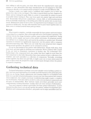
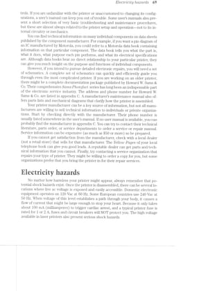
![/ Z. i)8i"‘l.-“L678 Q'Z.»L‘LC1/(3!/L‘7L€S
Static ioriuatiun
When two dissimilar materials are rubbed together, the force of friction causes
electrons to move from one material to another. The excess (or lack) of electrons
cause a cliaige to develop on each material. Because electrons are not flowing, there
no current, so the charge is said to be static. However, the charge does exhibit a
voltage potential. As materials continue to rub together, their charges increase—-
sometinies to potentials of thousands of volts.
ln a human, static charges can be developed by normal everyday activities such
walking on a carpet. Friction between the carpet and shoe soles cause opposing
charges to be developed. The charge on the shoe induces an equal (but opposite)
charge in your body, which acts as a capacitor. Sliding across a vinyl car seat, pulling
a sweater on or off, or taking clothes out of a dryer are just some of the ways that a
static charge can appear in the body.
Device darnage
ESD poses a serious threat to virtually all modern semiconductor devices. Huge
static voltages that build up in the environment (or in your body) can find their way
into all types of advanced lCs. lf that happens, the result for the component can be
catastrophic. Static discharge can damage bipolar transistors, TTL devices, ECL
(emitter-coupled logic) devices, operational amplifiers, SCRs (silicon-controlled rec-
tifiers), and JFETs (junction field-effect transistors). Certainly the most susceptible
components are those fabricated using MOS (metal-oxide semiconductor) technol-
ogy. A typical MOS transistor is shown in Fig. 4-3.
Silicon
dioxide Gate
layer
!'1""P‘!"V'f"§'‘ - PQWTPFT1 “4l‘l#‘fQ'0
1:15:15:1:I:Y:1$:?:?:i:l:1:I5:1:1:2!:12!:Izi:3:11!:>11513:113:1:1:1:!:1:3:i:¥:¥:1:1:l .~:1'-:1:-:¢:-:1:t!:F:1:i:i:i:I:!:i:5:-'i!1:¥:=:K:3'1$'-1:1"!:-:1:-'5'?-'-31' "1:- ‘w.-.'.-:*-:~:w.- ~.-:—:<~:-.-:-.-<-.-
"2-1513?. g>=.w_w v.=r-..|».<I=1.I.:2Iei:aw ».= ».I.:“-.!'.f~‘.R-'l 2:52:92
_. . . . . 1 1 . 1 1 1_. . ._1.1'.|-‘._._ -:;:;:::::;!, :‘-,.»w-1.,1,T;1;.;-1.<i‘.i1,‘:‘-1--1;§i1§1§1,§1;1p+; 1:31,-;§'l . 1 . 1 - 1 1 1 . . 1'1 1 1 1 . . . . .
Ivvvrlllli II i1:<_1P')E_‘I'tT—,I2»%"J¥r,li v IIIIIIIIIII ollulloo
. . . . 1 . . . . 1.1_.‘._._...'1|.‘.‘._ ;:;:;.;.;.4 ='i.,,:-;..§.:5!,:1§1:1'%1-:1i;'¢;v,;1;1;1;§1,5; _;3::I}-;.j‘. 1 1 1 1 1 1 1 1'1‘. .‘. . . 1 1 1 1 ._.luruuvunzan 1: -,‘:;,_‘,€h;‘i:__‘>l.?~‘I--_‘jmgl‘§‘=:$ib- IIIIII hl CIIIIIO
1 1 - - 1 - . . 1 1 1 1 1 . . 1 1 - . 1 . . .;.:-$1.51 v.1-:511-1§1=:1>~1~12:1-w.~1ii1‘.-.~:1=;.»:.'# -;.'-;.;¢.;. . . . .'1'1 1 1 1 .'1 1 1 1 1 1 1 1 1 1...........11.1111111. _11_.... .~1_,...1....1.1.11.111111
1: . . . . . . . . . :.:-:-.-.-:-:- -:-3 . . . ."
r ‘ ~‘ t 3A .*.---.--;_:_;~ - i 1-1
. 1 . 1 1 1 . 1 1 1 1 1 1 1 1 1 1 1 1 1 1 1 1 1 1 1 1 1 1 1 1 p' 1 1 1 1 1 1 1 1 1 1 1 1 1 1 1 1
1 1 . 1 1 1 1 1 1 1 1 1 1 1 1 1 Q.i-"1';-.;,_i=.11>=,‘¢_.—.1'.»5:1.5-»!:~;1ir., 1 1 1 1 1 1 1 1 1 1 1 1 1 1 1 "[5l::!1'Q§YI,!f‘!‘H!l7!"_I‘=K y 1 1 1 1 1 1 1 1 1 1 1 1 1 1 1 1 . j '
11,11-.g-eg:-lg:-,5 ig..~.,1..,1.~.q..i1,i¢g5¢s;!. 3. 1_.».,1..1.-.~,g.».-gq -.‘g-.-11,“ 1,1. pg .. I _. 1 . 1 - 1 1 1 1 1 1 1 1 1 1 1 %Eiq_i,,,'9,J-11..5__5,.HM,-.5‘!1 1 1 1 1 1 1 1 1 1 1 1 1 1 . ..,fl;i;5.i;._1,-111.‘: f 1 1 1 1 1 1 1 1 1 1 1 1 1 1 1 V 1 7
1 1 1 . . 1 . 1 1 1 1 1 1 1 1 1 'p_uj4j;:-xii-;>'1=*zz]i.;fl§i#"!1[§Q;fi;~:,1 1 1 1 1 1 1 1 1 1 1 1 1 1 1 =.1;'»iq'»-'.§'-""n'!‘11"l-'u':§'ij~‘i 1 1 1 1 1 1 1 1 1 1 1 1 1 1 1 la ‘ I I O 84 1.
-'--l"l'rI»,p‘..l¢¢»1:!~l!Ir'ilifist 3-ivy 1121 .|:|u:1>-11 1 . . 1 1 . . . - 1 1 1 1 1 1 1 i.~:<£r.~‘;,~.;!'.+,,,‘..mi-q;;:§;r;~ri,¢i'g . 1 . 1 1 1 1 1 1 1 1 1 1 1 1 L‘§FkV5iv>?‘:‘:!TiI:".L:‘ 1 1 1 1 1 1 1 1 1 1 1 1 1 1 1-... ...1<,,..H1 . E
. . . . . . . . . . . . . . .5-.!'1'»'=;%‘,?1fi,d:!?ir!i:5i§;5’ . . . . . . . . . . . . ‘l . . . . . . . . . . . . . .1 -
. . . ~ . . . . . . U"l.I1S1SlLOI‘. 1 1 . . .1 1... .11111 ,' 1111111 1 -
I I I I I II I) IIIIII attugnliill IV Ollfliiiblllllli [L L‘ '
1 1 1 1 . 1 1 1 1 1 1 1 1 1 1 1 1 1 1 1 1 1 1 1 1 1 1 1 1 1 1 1 1 1 1 1 1 1 1 1 11 -1 111111 111111
- 1 1 1 1 . 1 1 1 1 1 1 1 1 1 1 1 1 1 1 1 - 1 1 1 1 1 1 1 1 . 1 1 1 1 1 1 1 1 1 1 1 1 1 . 1 1 1 1 1 1 1 11
. 1 . . . . - 1 1 1 1 1 1 1 1 1 1 1 1 1 1 - 1 . . . . . . . 1 . 1 . . . 1 1 1 1 1 1 1 . . . 1 1 1 1 1 1 1 1 . 11
i . . . . . . . . 1 1 . . 1 . 1 1 1 . 1 1 1 . . . . . . . . . . 1 1 1 1 - 1 1 1 1 1 1 1 1 1 1 1 . 1 1 1 1 1 . . . . . . . . . . 1 1 1 1 1 1 1 1 1 1 11
. 1 - 1 . . . . . . . . . 1 . . . 1 1 1 . . . . 1 1 . . . . . 1 1 1 . 1 1 1 . 1 1 1 1 1 1 1 1 . . 1 1 1 . . . . . . . . . . . . . . - . 1 . . . .1
l . 1 , . . . . . . . . . . 1 . . . . . . 1 . 1 1 1 . . . . . . . . . . 1 . 1 . . . . . . . . . 1 . 1 1 . . . - - - . . . . . . . . 1 1 . - - 1 1 . .1
1 - ¢ . . . . . . . . . . . 1 . . . . . . 1 1 1 . . . . . . . . . . . . . . . . . . . . 1 . 1 1 1 1 - 1 . . . . . . . . . . . . . . . . 1 . . 1.
1 1 ¢ . 1 . . . . . . . . 1 . . . . . . . . . . . - - . . . . . . . . . . . 1 . . . . . . . . . . . . 1 . . . - - . . . . . . . . . . - - . . . 1.
. . . 1 . . . . . . . . 1 . . 1 . . . . . . 1 . 1 - 1 . . . - . . . . 1 1 . . . . . . . . . . 1 1 1 1 . . . . . . . - 1 . . . . . . . . - 1 1 . 1.
. . 1 - . . . . - . . . . . . - . . . . - 1 1 . . . - . . . - . . . . . . . . . . 1 1 . . - - - . . . . . . . . 1.
. . 1 1 1 . . . . . . . . . . . . . . . . . . . 1 1 1 1 . . . .1-1. ..-... 1.11..-..-... 1.1-1‘
. . . . 1 1 . . . - . . . . . . . . . . . . . . . 1 1 1 1 . . . . . . . . . . . . . . - . . . . . . . . . . 1 . . . . . . . . - - . . . . . . .-
. . 1 1 1 1 1 1 . 1 1 1 1 1 . . 1 1 1 1 1 1 1 1 . 1 1 1 1 . 1 1 1 . - 1 1 1 . 1 . . . . - 1 1 1 . . 1 1 1 1 » . . 1 1 . . 1 1 1 1 1 1 1 1 1 . . 1 1
N-type substrate
Drain Source
MOS devices (PMOS, llMOS, HMOS, CMOS, etc.) have become the cornerstone
of high-performance lCs as memories, high-speed logic, microprocessors, and
other advanced digital components. l/lOS technologies offer high-speed, high
component density, and low power consumption. Typical MOS lCs can easily cram
over 1 million transistors onto a single lC. Every part of the transistor must be
made continually smaller to keep pace with the demands for higher levels of inte-
gration. As each part of the transistor shrinks, however, breakdown voltages drop,
and ESD damage problems escalate.](https://image.slidesharecdn.com/ozgdplurrtdj8c4ktjrb-signature-f36449d24fae8f28749ba408629a60e09bfd643da03035012a2b233e7710df3e-poli-180806114914/85/Easy-laser-printer-maintenance-and-repair-78-320.jpg)
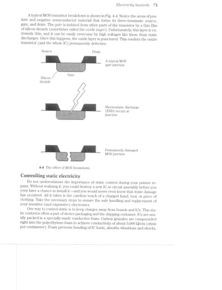
![74 S6'7""U'Z-C6 ,c]'tz.i'2l<i£cl.mcs
and its conductivity helps to keep every IO lead at the same potential (also called
€(]’LL'Z;].')Ol§€?'7‘Zl§'2;Ctl OO'l'?,Cl?;’l‘2,Q). Conductive foam is reusable, so you can insert lOs for safe
keeping, then remove them as needed. You can purchase conductive foam from al~
most any electronics retail store.
Oircuit boards are normally held in conductive plastic bags that dissipate static
charges before damage can occur. Antistatic bags are made up of different layei‘s-W
each with varying amounts of conductivity. The bag acts as a Fdmolag./ cage for the
device it contains. Electrons from an ESD will dissipate along the surface layers of
the bag instead of passing through the bag to its contents. Bags also are available
through many electronics retail outlets.
Whenever you work with sensitive electronics, it is a good idea to dissipate
charges that might have accumulated on your body. A conductive fabric wrist strap
that is soundly connected to an earth ground will bleed away all charges from your
skin. Avoid grabbing hold of a ground directly. Although grabbing the ground will dis-
charge you, it can result in a sizable jolt if you have picked up a large charge.
Remember to make careful use of your static controls. Keep lOs and circuit
boards in their antistatic containers at all times. Newer place parts onto synthetic
materials (such as plastic cabinets or fabric coverings) that could hold a charge.
Handle static sensitive parts carefully and avoid touching their metal pins if possible.
Be sure to use a wrist strap connected to a reliable earth ground.
~ e '
wi -i .- -4 -". ‘-‘-<= " . ‘F ~ i, ‘-3 ,~‘ ‘:1? ‘-52 we ‘-is L: T"-J». ‘ 5-: '1‘ 5'-1
“‘ '-"~ 1‘ ‘$5 "Q -'2 I *1, 5" 3" "Y >5 E11 "5 5“ "R E3
Sooner or later, you will have to disassemble your laser printer to some extent to
perform your repair. Although the actual process of disassembly and reassembly is
usually pretty straightforward, there are some important points for you to keep in
mind during your procedures.
iieusirig disassernbiy
Most laser printer enclosures are designed as a series of covers that are latched
together. By opening the top cover, some assemblies should be exposed. This gives
you quick and easy access to replaceable parts (such as the EP cartridge). in many
cases, however, you will have to remove additional housing components to access
major assemblies (such as power supplies, the fuser, and main logic). Examine your
enclosure very carefully before beginning the disassembly. Some enclosures are held
together with simple screws in an obvious, easily accessible fashion. Other types of
enclosures use unusual screw patterns such as Spline or Torx. They also can incor-
porate cleverly hidden internal clips that latch the enclosures together and provide
a sccmz..Zfcss appearance. Seamless housings might need special tools to disengage
these internal latches before housings can be separated. You might like to get an~
other persons assistance when disassembling this type of housing.
Eieetrenieeiiariieai disasseiribiy
Safety is critically important whenever you are working with electronic circuitry,
se be sure to ENPLUG ‘THE ?RiN"i‘ER before starting any work. Plug it in](https://image.slidesharecdn.com/ozgdplurrtdj8c4ktjrb-signature-f36449d24fae8f28749ba408629a60e09bfd643da03035012a2b233e7710df3e-poli-180806114914/85/Easy-laser-printer-maintenance-and-repair-80-320.jpg)
![Rcdsscmbly and disassembly lzmts 75
only long enough to follow your particular troubleshooting and testing procedures,
then unplug it again.
Laser printers contain a wide array of electrical connectors handling everything
from ac line voltage to laser control signals. During disassembly, you might have to re~
move one or more connectors to free a circuit board or other subassembly. Never re-
move a connector by yanking on its wires~—many connector shells use keys or latches
to hold them in place. Always remove a connector by holding its shell. Take careful note
of each connector location and orientation. Some connectors are keyed so they can
only be reinserted in their proper orientation, but other types of connectors might not
be this foolproof. Make a sketch of where everything goes before taking things apart.
Take careful note of physical parts as well, especially when you must disassem-
ble complex drive trains of gears or pulleys. It will help you tremendously when it
comes time to reassemble the system. Mark your parts before disassembly with an
indelible felt-tip marker. Feel free to use any kind of markings that are clear to you,
but marks should show how each part is mounted in relation to its adjacent parts.
Fig. 4-5 is just one simple example.
..-.~=":*T.‘-7'72-.-.. Z Geart1“ai1"1
-I ._.. _.r..........-.-I.._
................._
,-- . . . . ..............
I:-_-__‘ _ :1 J.|r..._.............
'1-II Iu||roIQnvIInL*Il‘I -.5 -I ..-...-I.--.I..L.
|--I-- III, ~I. -I-.I.-I.-IIIIII.
'.'.'.'-'.'. I-.-..-. -..'.'.'.' I".'... ""'°""'.'."""
IAIII DGIIIIUIQ IIIII blllb ll
‘1..... .. I
InIvI IIoI»IovIII-IIIoIIQI ~IllQUIIDIlllIIII III
alt: IIIIIIIIIIIIIIIIIIIII Illnornou-I|aIIII|¢n II’
IIQI ICOIIIIIIDIIIIQIIIIQU lIIInI~IIIIIInvnIIIcu Ill
I¢uI¢ QIIIIIIIQIIIIIIIIIIIOi4IUVIllOIIIbIIIIlIII‘ ll
..-..... .I..-..-‘.-‘...-..I....-I. .-..-I...-..--I-..-I. I........ .-I... .._., -......--I... -..........I-....-..- I..-I
I... I‘IIUIéI:I.I'l‘1|DIIIQIIIIII II...-..II....I-....I. IIII
IIIQI IIIIII,O'].I‘I'I.tIIlII!IIQlIl QI,IIIIIIIII-1;-|¢ul_III,-IIIIIIII
I... .II... -I.-‘I .....-...... .-.....-..- . ...-..-.--.
IIICI .....-.;I;-'._......-II- I.II...I.-III.,PI'.-.:.{.;.-"l,..II.....-I.
IIII zIIIIIIII‘wIIIIoIIIIIIIIIIQIIII'I'I'IIIIIIIIIIIIIIIII
.....,II... -I....-a.I.I,....-..I.. I.-I.I...--
I.-I -.II.......I.-.._.... .. .....-I -I5.-._._.-.;._' -III...-... _..I-- III0lIyIIIIll|IIIIIIl .-.........;}_:F.;.5_::;;.'I'........-..
I... Q4IIIIII4IIIIIIll1III ..-.....-.. .... ..-I....... ',.... nnieg-- -.I..II. .......I -.--.--I...-.'-.-.'.'..-.......-I.-
;II ......II -III-III| IIIIII.IIII.'I'I".II.IIIIIIII
Y‘ ..-I..... -I..... I...-..-I... --.I..-I----.
‘I :.:.:.:. :.:.:.:.:.,I‘ 1;.:.:.I.I.2.'.'.'.:.:.:.:.:.:.:.:.:.:.'.'. '.-.:.:.;; n’1EL11S
|" i;|‘ |-III IIIIIIIIIII II‘
III IIII IIIIIII-III »I
I IIIDI IIIIIIIIIII I||
-.1 I-...I.--I-I P 1 II.-
1 -I'I'n.I'I'I-I.I'I'I'I'I' ' I I I I I I I I I I I III. ‘II.
"IIlbIlIlIII1IIICIr lllényuulul I 11'
_I.II~II-»IIII~II_ IQIIIIIIIID II_I'
.._. . . . . . . . . . .._. .._._,_; . - I I . . ._.__,... J . - . - I I I I_._._- I - I ,:_TIT._. .—I__
-*-.1' ' '-'- . . . . . .'.'.'.'I._
-‘, I I . . . . . ...,,-I";-In ...........,..,,_ . . . . . .._,_..)_._._.
IIICIIQIDIIIIIII}
IIIIIIIIIIo¢IIIE
!IIIIoIII¢IIIIIII
..-.-I.,._._.r_ IIIIII
I_I....I-......-._I
IIIIDIOIIIOIIII‘
...I-I.»-......
_ I I I I I I I I I I _
nu:-l I . I I I _ I I I _ I ‘I&:‘_~
I-UL I I I _|_uI
5;»-5 Making alignment marks before disassembly.
Reassembiy
Whenever you must replace IOs on a through-hole printed circuit board, always
solder an IO holder in its place, then plug the replacement IO into its holder. Printed
circuit boards (especially complex boards) are very delicate, and printed traces can
be damaged by excessive or repeated heating. If you install an IO holder in its place,
you will never have to desolder those points again. To replace that IO in the future,
just unplug it and install a new one. Keep in mind there might not be enough room
to install an IO socket if the board is located close to an enclosure of another assem-
bly. Use your best judgment to decide if there is enough room for a socket.
I Always double check your connector locations and orientations before applying
power. If a connector is engaged backward or is skipping pins, your circuits can be
seriously damaged. If you have made orientation marks on the connectors before
disassembly, they should be a snap to install properly.](https://image.slidesharecdn.com/ozgdplurrtdj8c4ktjrb-signature-f36449d24fae8f28749ba408629a60e09bfd643da03035012a2b233e7710df3e-poli-180806114914/85/Easy-laser-printer-maintenance-and-repair-81-320.jpg)

![The 6’l€Cl§’i=”O_]3/Z0l§OQ’l”(it];)/2/2:6 (.TL]f)]3’}~"'OCLC/"L 79
Photosensitive
outer layer :,_,,¢,__¢:;;.j;",§;"'";;;_:;';*;;'1;;,,1?
.‘.‘...,..
A""--’_.,'_I:§:Z:E:7:E$:
-»:':g;:;'
2
~
';1:!:Y:!:?:1:1:!:1*-':_‘=*'-' - ¢EI?5Y‘1‘3E$*".'i.-1;}-'
—-'*¢‘.‘-:-'-;-¢-:-:
' .;.;.;.:.;.;.;.: .':'I‘I-:':':'I" ..__2;.
.Aluminu1n J i
structure ;~.-.-
I- _.;z.‘_;;;._ .~j;;§=;;5
-I :<:==a= .s=2:>==2>s =a=z2:2:s -:- -:-:-:-:4:~:-:~:-:-:-:-:~. "'—=.<;e ;=;==r;-21-,=: r=>';z== 1'“ '1
-. :1:?:1S:- 1:T:1:1:1: H
1- 525255255! .isEz¥£E§5=* 1-" :~:~:-:-:-:-:-:-:-:-:-:- 3 3- _-.:-:»:- ./ ' I, -:-:-:-:-: - - - ~ ~ - - - - < ~ - -
Diag'i.‘a.1"n Oi a photosensitive
(EP) drum.
'~-__-,,-.".".-.-.-.-.- gr’ ~—“'
High-voltage
povver supply MW
, assembly ‘
l‘; is the drum that actually receives an image from a wrilt/mg /meclz/cm'zIsm, de»
velops the image With toner, then transfers the developed image to paper. Although
you might think that this constitutes a print head because it delivers an image to pa»
per, the image is not yet permanent--otlier operations must be performed by the
lFS. Complete image development. is a six-step process that involves all eight IFS
components: cleaning, charging, Writing, developing, trans;i"'ei;', and fusing. To under~
stand the IFS, you should knovv each of these steps in detail.
Qieaning
Before a new printing cycle can begin, the photosensitive druin must be physi-
cally cleaned and electrically erased. Cleaning might sound like an unimportant step,
but not even the best drum will transfer every microscopic granule of toner to a page
every time. A rubber cleaning blade is applied across the entire length of the drum
to gently scrape away any residual toner that might remain from previous image. If
residual toner Were not cleaned, it could adhere to subsequent pages and appear
random black sgaeckies. Toner that is removed from the drum is deposited into ade-
bris cavity as shown in Fig. 5»-4. Keep in mind that cleaning must be accomplished
Without scratching or nicking the drum. Any damage to the photosensitive drum sur~
Photosensitive
. outer laver
Rubber cleaning "
blade
v-»FI_‘fi_I_I-1
'-'-'*-I":-..-.~' +153:-':>.<:r$155=s:::2=e1:=s$:I:r:<=£5€2¢+ IV-_‘_“l‘AA_--- - - .r.f-:-:-s:-:-s:-'-:+:-:+::»:-5»:-:-:-:~:-:->:-:-r-2:-:-:3:-1, - - -'-.
- '- ' 1»k¢:=-5§=E=§¢§$=E€=E1E=3=¢*'?"“"""'" ' -1--' - »' ~Z?‘£3I3.'7l:I1§-I-Z12H- ».'-:-:-:-:-:':»5:-:-:i~t.,‘- -
' . ' __-$1:-:;:;:;;:-"-7* ‘J:--:-:~:-:-'-r-:1:-. ' .' .
Cavity Simpliiied diagram of a drum
ii 1, 5 J 52'
.._.--.-‘--._ ..-.-.1:-;~:-M-:~:-§2-4;....;._~.;_.~,.;.'~7:¥'!:1:1:5:1:I:7:i<5:‘:1:~:-:1:-:,l;.;2;.p-<-.-.a-.~2-.-.-.-4.5.1.1.
>'I,-‘F
- ,,-rm.
ttE,-
2
=E=E>I:-:-:Waste . . :z;.=;s;s;a;s .-:<;t;:;:;:;._ '-__ _.;:;§:;:;:-
T - . g:-:¢.=:s:s-z:z;a ; .¢z2=z:srs:s~i-:-ze
Y ' " .- l ‘ ".".‘E:E:E:}:;:E:§:j __-' "-._ j;§;=:§:§:E;§:'w‘.'." '
’ ,.-"».-:-:'e=22=s=s=s§a:'
, .- -A -' "-'-I-'.'"‘=E£§£§E§£;i;i;-. _.sE§i55;E5a;~I==-'_'-I-'-"
* " ‘ ’ " "‘ “'4
"~=-=:-:- -:=-1-'
—._,;.‘.:-:._,_. Ha . .-.-.~.-,_:-"
-»__,. . .'.'.'.-.-,;..-—-
ii-L’ ‘ ' ‘nl~I"](https://image.slidesharecdn.com/ozgdplurrtdj8c4ktjrb-signature-f36449d24fae8f28749ba408629a60e09bfd643da03035012a2b233e7710df3e-poli-180806114914/85/Easy-laser-printer-maintenance-and-repair-85-320.jpg)
![8% E[€CZ‘7"'O];)/‘Z10ZOQ'7"Ct1U/‘Z'ZC tec/'2.r2r2.ol,ogy
face would become a permanent mark that would appear on every subsequent page.
Some EP printer designs actually return scrap toner back to the toner supply for re-
use. This kind of recycling technique can extend the life of your electrophotographic
(EP) cartridge and eliminate the need for a large debris cavity.
images are written to a drum surface as horizontal rows of electrical charges
that correspond to the image being printed. A dot of light causes a relatively positive
charge that point. The dot of light corresponds to a visual dot in the completed im-
age. Absence of light allows a relatively negative charge to remain and no dots are
generated. The charges caused by light must be removed before any new images can
be VTl'ltt€llM~m~OlTll€1'VlS€ images would overwrite and superimpose on one another.
A series of erase Lcimps are placed near the drum surface. Their light is filtered
to allow only effective wavelengths to pass. Erase light bleeds away any charges
along the drum. Charges are carried to ground through the aluminum cylinder as
shown in Fig. 5-5. After erasure, the drum surface is completely neutral»~—it contains
no charges at all.
Erase la.mp
Photosensitive
0011901 " / outer la+-fl.........J_'.1:v:|-b- 13/551“. . .<'.-.-.~ +;5!F3=:s:=:311;:;=;=;r=;=E=s=1;=:=;=:§!n,- .--
—, w w t .
V-S ~. 1‘.-":',' :3r:5:?J:1:=:>:7:?:1$"*'> :'%:$:I3:1$§i§E "xi"-_.—-. ".-‘ - .-:-:-:-:-:¢-:-:-:;;;4-*" "H-1;:--:<;'-:->:-.-. -
' ' ,-. _.;r:-:;:;:;r_:;:;;r~ 4.';:-.-:-:-:-:-:-:-.
I Aluminum-. .- .115’:-5:1? "-. .-‘ .1:=:=§:1:?'3:$-'- K
.__" * *-r==a;§>_=» .
i;__,:i.~:=r§;::%a=; i structure
.~_. rt-1 ht-1:?-F35: I-:1
-|l"1'k-._ I-I 3315151513 "i1:=E=EE=:=? $513533 I-I
tatic 3 ..
"1_I- 1-.“€§E=E§i;5ji§;;.-:_ ;¢.;.3%'>'5i?;EEE=' '.- I -I_r"
. "E-:-:-:-:~>E:?}»,§,-, ..v:-15%-:-:~:>!-Z-:»' .'.'.,?
Cllali‘O £3S ._, , - . ,,._.,3.,.1._-g,_.,._.,-_._.,,,>_,$'0;-3-3,'-1". . ‘,-
tj "-." -' - "-"¥:k7'1.’~:1:3$3:1:1$;=:$:' 'i:1:1:$?;;'<%?.?*5£=*'::" - ‘ - ‘.-"-~:,_- . I . 1 . "¢*§-Q-:-:-E;:;:;:; :;:;:;:;:-‘E-.15-;q|* . ' . ' . ' ,_'.--
.,_,_0
-.,,......414i .....'.',;-"
-'-;,_'.'.'.'.'., .'.'.'.'.';..-
.-__-
can-Q
-.1
5~5 Discharging the EP drum with an erase lamp.
Charging
The neutral drum surface is no longer receptive to light from the writing mecha-
nisin. New images cannot be written until the drum is charged again. To charge (or
CO'i‘Z.-CZ1'i1Z’ZO'i"Z») the drum, a uniform electrical charge must be applied evenly across its en-
tire surface. Surface charging is accomplished by applying a tremendous negative volt-
age (often more than —6,000 V) to a solid wire called a prilmciry coroner located close
to the drum. Because the drum and high-voltage power supply share the same ground,
an electrical field is established between the corona wire and drum as in Fig. 5-6.
At low voltages, the air gap between a corona wire and drum would act as an in-
sulator. With thousands of volts of potential, however, the insulating strength of air
breaks down and an electric coroitct forms. A corona ionizes any air molecules sur-
rounding the wire, so negative charges migrate to the drum surface.
The trouble with ionized gas is that it exhibits a very low resistance to current
flow. Once a corona is established, there is essentially a short circuit between the](https://image.slidesharecdn.com/ozgdplurrtdj8c4ktjrb-signature-f36449d24fae8f28749ba408629a60e09bfd643da03035012a2b233e7710df3e-poli-180806114914/85/Easy-laser-printer-maintenance-and-repair-86-320.jpg)
![The eliectrop/totogmplz/to CLj;7]97”OC?,(3/Z 8i
l~ligh-voltage
power supply
Primary corona assembly
_g i i i 6 kv Charging
voltage
Primary grid
g , ,_ Regulating
ilElllillillllllllrlIHllIl!lllIll'kll*1'r - ~ - -- V Voltage
|'_|lt — —— ‘ll _|'}I
..'-;-;.:.;.;._.;.~.-~ . . . . . . . . - < - . -*.-.;.;.;.;.;.~.-.521‘ .
- - - -;a'=’s':==:=5='<2&~'t‘~.-:-'-:-:-:-:-: :~2-t-:-:~:-: :-:-:-:-:-:-:~:7?*r%==z=s:z§5és==-
PllOi,OS€llSll}lV@
drum --—~
' 'rl'...... _’____,________ . . -|' ""'--i‘::::::::;q|._-_._._._._. __ H‘ ~. ._-_-_-_-'._."¢gEE§;::
»fi:s=:=:=r~:-:-:~:-: ' *"—5- -4*
:§§§§§§si;§;: :3,-| ‘_:__F___~ USQ Of 8 COl1L1*()l §,*1‘lCl
-:-:-:-: - - - - - __A _ V ____Mi!''''''''' -‘ii _______ Elf-iii? V
on the drums surface
5-6 Conditioning the drum with the primary corona.
wire and drum. The short circuit is not good for a high-voltage power supply. A pi"?L-
’7"7Z.~Ct'}”’LZ] Q’?"’Zd (part of the primary corona assembly) is added between the wire and
drum. By applying a negative voltage to the grid, charging voltage and current to the
drum can be carefully regulated. This 7"‘6_Q?,l,lCiJ?2l’)*’LQ grid ‘voltage (often -600 to -1 ,0OO
V) sets the charge level actually applied to the drum that is typically equal to the reg-
ulating voltage (-6OO to -1,0(lO V). The drum is now ready to receive a new image.
Writing
To form a latent image on a drum surface, the uniform charge that has condi-
tioned the drum must be discharged in the precise points where images are to be
produced. images are written using light. Any points on the drum exposed to light
will discharge to a very low level (about -100 V), and any areas left unexposed retain
their conditioning charge (-600 to —l,O0O V). The device that produces and directs
light to the drum surface is called a. ’2.mi'"zlt2P2-t2.g ‘T7266f2rCl/7‘?/Z:S’I?Z.
Because images are formed as a series of individual dots, a higher number of
dots per area allows finer resolution (and higher quality) of the image. For example,
suppose a writing mechanism can place 300 dots per inch on a single horizontal line
on the drum, and the drum can rotate in increments of 1/soc of an inch. Using these
specifications, your printer can develop images with a resolution of 300 >< 300 dots
per inch (dpi). Current EP printers are reaching 600 >< 600 dpi.
Lasers have been traditionally used as writing mechanisms (thus the name
“laser printer”), and are still used in many EP printer designs, but new printers are
replacing lasers with bars of light-emitting diodes (LEDs) or arrays of liquid crystal
shutters (LCSs) to direct light as needed. (Writing mechanisms are covered more
extensively in this chapter.) Once an image has been written to a drum, that image
must be developed.](https://image.slidesharecdn.com/ozgdplurrtdj8c4ktjrb-signature-f36449d24fae8f28749ba408629a60e09bfd643da03035012a2b233e7710df3e-poli-180806114914/85/Easy-laser-printer-maintenance-and-repair-87-320.jpg)
![$2 Electrrop/totogirctpfzic rec/mology
fieveloping
lmages Written to the drum by laser or LED are initially invisible---merely an ar-
ray oi’ electrostatic charges on the drum surface. There are lovv charges Where the
light strikes, and high charges Where the light skips. The latent image must be de-
veloped into a visible one before it can be tiiansferired to paper. Tone";/* is used for this
purpose. Toner itself is an extremely fine povvder of pla.stic resin and organic com-
pounds bonded to iron particles. You can see the individual granules under extreme
magnification of a microscope.
Toner is applied using a toner cylinder (or cteaeloper‘ ’)"'OlZ€’}") as shown in Fig.
5-'7. A toner cylinder is a long metal sleeve containing a permanent niagnet. The
cylinder is mounted inside the toner supply trough. When the cylinder turns, iron in
the toner attracts it to the cylinder. Once attracted, toner acquires a negative static
charge provided by the high-voltage povver supply. This static charge level falls be—
tween the levels oi‘ the exposed a.nd unexposed charge levels oi’ the photosensitive
drum. The drum levels can be from ~2OO to -5OO V depending on the intensity con-
trol setting. A restricting blade l.imits toner on the cylinder to a single layer.
Photosensitive
Chum li.estricting
m blade
. I""3§j§E=E=E=i=§=3=:=:Y‘!=.w,.‘_1_._1_1_1_1' :i1:§:;1|:;1_€:;:;:::;:_:;_‘r .......................__~.,».1....T..............................fi..".._.._k_._....“V...........................~_..,_._..,...... ........................ Q
1 1 1 1 1 1 1 . 1 1 1*L;h:j1§1;1'-315131;. 1 ;1 1 1 1 1 - 1 - - 1 1 ;‘;:1j1,1,1_»|1'1_ 3
:-'-2-":0:-:-_ 1
l
~.-.-.-'s;=;=.<;=;=-===. *‘___...-11--11'1.11r1xq:;:::1;:§:$‘~1 I
"1"" ‘-H"-I-Z’. "-1., . . . . 1 . . . . 1.-1-1-2-.-.-:1‘.
"-;. .~ “ " *.‘.'.‘.‘.‘.‘:|hl~1‘;Z;§iEI;:i1l 1 “*1 1.: “ if F‘? ‘, " ‘,
-g I I - -..'.-.;.; : _ H :2 Ii :
. '. '.-.'$:¢:I:¢:¥:I§‘ ““ 1. {~51-:¥:I5:I:='1'I"""""""*>1*$:I§I:I:-:14? ‘F "1 .1 ' . ' . _ . _ . _ . . ;i_~1;.£:;.;‘_Ji ii i E “ _.;1;1{.§§ :.§1;1§.'._ 5 1:
. . . ' 1 1 '1'.‘ 1.. '1'1".".'. ' » 1». 1 » l
‘J-‘-'-'-'.‘1‘1':'l-:§3E~I'<i '2-§:g-'-29%.-:'.‘.‘.'.‘.'.’."'7-:'-Z~'-Z-I-I-I-.,~f1,*“*.. i| 1 1 1 1 1 1 ¥-15,1;-11;-§ l _.g.;.;$,4*'_.*1 1 1 1 1 . 1 . . 1 v._ ~.2_1.§.g._ .» .; » = . -= u 1. , ,3. . . . 1 1 .1.”-,:_,1_1 l 1: _1_1_:‘1 J-1 1 . 1 1 1 1 1 1 1 1 1 11-. 1_1_¢,1_ r, J» V, _,
1 :~_-_'_' ' - 'y;.'1_.'1'1'l _ 1.--‘1'-‘fl * * ' * ' ' ‘ ~ ' ‘ " ' "1 '1--1-1 .- .‘,- _: ~ ,4.
1, 1' . . -:~.-:-:~.| 1",:-:-:-:-:-. 1 .-:~:-:-:-~ .- .» -' ’. T .. J1 1 0 ~ - - '-""-'- ' 3'1‘-‘I 1*. 1 1 I . 1 1 . . . 1 11‘. '2-'1‘. /‘J P " ‘-' ‘ ‘* 1‘- ‘ ‘ l'
I 1 . . . 1 1 15'1". 5 >1’: I. 1 1 1'. 1 _'v'-r‘._ 1 . . 1'1 .1 K,‘-“.-' ,' _ " - .‘."~ ,~ r- .
| 1 - 1 1 . 1 1:-{1;,"3 _ri!§.)1;1"r|. . . . 1 F11 1 1 . 1‘-.. 1 . . . . :‘7".1.;.j ,. ;v,- _._=_,-‘.~_.r“ '1 ,3:i 11-111 ‘:13-_ .51,-_111111)-11111-1n-111-.: _. _ .1_!
__L ~" ;:;:;: :;:;:; 1- ,.... L‘ I 1_-.._1_-_1. :.::$:. u 1:$::: i1'1'..._1‘_1.1'1‘1'1_1_1'._1'1'_1'.'1'§ :::::: ‘ ’__"__,:_,;i~ _~ ,,.-J ,. . ‘git .
.1 : ;:;:;:. . 1 . 1 1_._1_. . . . . . ., ., . . . . ._._._ K... _ _.~ . . F p.... ......._._._._. S _.._. ... . ..... ,.
1.4 ...... -.-.-.-, .........r-... .... .-.-.- .~.,.-w1-q 1......‘-.1i.'.*1 *1;)'- 111.1... 1.1.1..11,- 111111 1;1_,»;1;s w la 1_-:1;].1..¢1¢1 1.1.1.‘;-3 ~'.'w.~’~:-,_-‘ ,1_:_. t _1_1_1_1_1_ _:_:_:‘5 an 8 Ii -,:_:,_ t_1'1_1'1'1_1_1'1 1_1_1_-_1_1'1l __:‘:_1 V, ‘ l;A,,v». I,1v{é _,, _ 3.‘,
{ 1 -_1 1 1 3413111; ,1 u ;1;1:1;&l,. 1 . 1 1 1 . 1 1 1 . . 1 1. 1 . 1 1 , r sis’.-- .--_-,1,-,1, ,--111111111111-..., .
.-* J:-:-1-:-:~I1$E=2=z:s==:1 ‘s¥sEz===1.'=:-1-:-1-:-:-:r:-1-:-:-:-:-:-:-:~'i'.=-EE=====. TO‘ E‘ " S 3 El Y“ I‘ l r ly 3a§§<¢»¥** 1 . 1 1 1 . |;1_.;1;.{1A ~.'.',g.§ . . . 1 . . 1 1 . 1 . ,."_,§;-;._ ~ .1 '
1*" £'.'.*.'.'.'.+.-zr:-:-:-:1 '-:-:-1-."-: '.-" .-:-J~:~' ~* I '-.2 -- 1 . 1 1 _1-11:-3' .~.~11"» . 1 1 . 1 . 1 1 ‘ 1 ~.~.-1-1 V »-' ' '=-* .1r. 1 1 . . 1 4-1'1... .» ‘iii’? — xxgzfifa-' r
‘ *;“;'I.§§:iL;i};f.L“__;‘ _ 7 3 ~ Q '~ ' ~~
- . C‘ L Opu 10 61_ “.'.'.'.'.'.'.'.'.-:~:¢:5:;:1:3:}'11 ~‘ i *
_ q— ‘§:;:;;§:g:;:=-1;, , ~11111-111111. _1_1_1_1_1_.JllIIlInIO"Ic‘i.V‘I.l ~
‘-$i:Z:25'3;3$$;{‘ l/[qo1'1(31 Qgre1 1 1 1 1 “U . . . . 1'. .,;gfZ;.;.;;.;§.;;L* ll l C-'6 J -1
.'.'.'.'._;.e§:;:;:§:;:;:;:5f ;
.‘.‘.'1‘1‘1‘ .'.'1’ $'1§¢$gi;i3I'§"]i~‘ .. 1 1 1 1 1 ._fi1|.1;|fJ<,1;_.;.$1_:;I:; i.
' ' ' - ' ' i. '1-1-1-1'1-11'.'.-1--*1’* ~ ' ~11.-1-.*.'.~.~.;.;.;.;.-,3;.1 1' 1 .-.~1>.*.'.'. 1 . .1‘. ...--~'..__ - ._
:';:;1;:*:~:-';:;:§¥-:§:~e1:5:-;;§:£'*"' ,-" 1"'| '-,
-.».-.=:-:~: .' '- = | 1 1-.-~.'.~ -‘$41 r I i ‘ 1'
5 .- l3ooster1 I I 3 ‘ ‘ " '
Q T bias (ac)
m_......... g _.
W iii: it--A-» n cnsl y
ll .1‘ ‘1 ' “z
WL bias (dc)
af-A
5--7 Applying toner to a charged EP druni.
Charged toner on the cylinder now rotates close to the exposecl drum. Any
points on the drum that are not exposed vv"il.l have a strong negative charge. This
charge repels toner that remains on the toner cylinder and is returned to the supply.
Any points on the drum that are exposed novv have a much lower charge than the
toner particles. This charge attracts toner from the cylinder to corresponding points
on the drum. Toner “fills-in” the latent image to form a visible (or developed) image.](https://image.slidesharecdn.com/ozgdplurrtdj8c4ktjrb-signature-f36449d24fae8f28749ba408629a60e09bfd643da03035012a2b233e7710df3e-poli-180806114914/85/Easy-laser-printer-maintenance-and-repair-88-320.jpg)
![Tire @l,€Cl;"'l~"'()p/2,0ZOQ'l"Ct]3/'L’ZlC dpproctclz 83
Notice that air ac boostei' (nioi.*e than l.,bOO X/pm) is added in series to the dc
intensity The ac causes strong fluctuations in the toner charge level. As the ac
signal goes positive, the intensity level increases to help toner particles overcome at~
traction of the permanent magnet of the cylinder. As the ac signal goes negative, in-
tensity levels decrease to pull bacl< any toner particles that might have falsely
jumped to unexposed areas. This technique improves print density and image con-
trast. The developed image can now be applied to paper.
Transier
At this point, the developed toner image on the drum must be transferred onto
paper. Because toner is now attracted to the drum, it must be pried away by apply-
ing an even larger attractive charge to the page. A tlrcmsfer corona wire charges the
page as shown in Fig. 5-8. The theory behind the operation of a transfer corona is ex~
actly the same that for a primary corona~»-except that the potential is now posi~
tive. This places a powerful positive charge on paper, which attracts the negatively
charged toner particles. R-€lll.€~El.'I.il‘)@i‘ that this is not a perfect proce —not all toner
is transferred to paper. This is why a cleaning process is needed.
U3 U3
Photosensitive
druj1.n %~ii..
i§i§?§1;1§I§1§1§I§1.lL ‘?.;§I§1§I§1§;-?' JJEIEI IEIEIZI 1»
1:3:3:3:3:?:T: '""““" 13:3:-.-:3:1:i “ --au "-
ii. u r 53:?'r7$!- , ~:3.":' II
£533: :3:1:§:'II<:§:g:;"._|._1_.’._141_ 1 . . . . 1 1 {,5-1.‘ ,;
P~:;:;:;. -:-:-:-:-:-:-",s;s;=-= -
L 4
31: — 3 1- .
1 ~ll~"~r1- ‘**~+iia=i1;1;r;r;1;1¢ 1:1:;:;:1=;=;=1:-an Toner. :,;;::g:;1_§,_._1_1_._._ _ _ 1,..__ _.a 1 1 1 1 1 1 1;fl;1;$i;;J:
_- - , - _.;.;.:.;,;._ 1 . . . 1 . . 1 .'1._ _.:‘.‘.'.'.'.‘.‘.‘.‘.‘.'.'_.;¢gl;2gl;., 1
(110 1.l€l- -I-I-I-T'1—.—~1... ...;-.-."*T-1'1-I-I-I’?I-I-I-I-I-_I,;;E§;E§§§;¥'j,;‘ paytlglgg
1 ,_ _. '-:;:;:;:;:_ y:-'=';:§:1;e' 3
‘ 1';i.]"<J 1.) “s:;;z=z;?§i;;:_ t_-:~:-:-.~.-.-:-:-:-:~:-:-:-:-:-:-:-:-:-:-:-:-:-:-:-:~:-:-' "
Cl ‘ UL
-- 1" _
"v-~-_."-*1“ ' _._-»-—“—11.1..__ I H H 2 :1 " —
"_"_-1?“ n I u n H // _-1-“-""'_-—_
'--'i"""W1 ‘L ml ° '1 " “E; an B}: n y __ ,,_.__ ‘T |__
A T” * A To l W -1 1-I-1___. "- 1 I “"-._
1% _ + '1' =+,'»,—l— +,- 3‘2-_--1"“ I‘: ~'-. 1“. |'.
"1_'~‘ '1__ L __1' '.|_1'
.._ I: 3 ___.
1-@-
~ + l ~lo1i.izecl air
Static/ l . ___ l
elin;unator ; Tl"<11'1$f61'llllllllllllll
comb ; corona.
assembly1; “W .. ~- - .. .. 1,.1.11..‘.i..,_- . 1,-.-.,1.1,,,a,“i¢-¢..=..1.=,..1_=.,,=.,.1».
- l
.. U» /High. voltage It A
power supply “"""'"""""'"""""*'":l
assembly ...
§“'“"'i
5-8 Transferring the developed image to paper.
Caution is needed here. Because the negatively charged drum and positively
charged paper attract each other, it is possible that paper could wrap around the
drum. Even though the smal..l»diameter drum and natural stiffness of paper tend to
prevent wrapping, a static charge eliminator (or <el*zlm/matter comb) is included to
counteract positive charges and remove the attractive force between paper and](https://image.slidesharecdn.com/ozgdplurrtdj8c4ktjrb-signature-f36449d24fae8f28749ba408629a60e09bfd643da03035012a2b233e7710df3e-poli-180806114914/85/Easy-laser-printer-maintenance-and-repair-89-320.jpg)
![84 Electropltotogmpizic tecltiiology
drum immecliately after toner is ti.'ansfei'red. The paper now has no net charge. The
drum can be cleaned and prepared for a new image.
Fusing
Once the toner image has reached paper, it is only held to the page by gravity
and weak electrostatic attraction--toner is still in its powder form. Toner must be
fixed permanently (Ol‘,]F7,L.S‘6Cl) to the page before it can be handled. Fusing is accom-
plished with a heat and pressure assembly ljilre the one shown in Fig. 5-9. A high-in-
tensity quartz lamp heats a nonsticlr roller to about l8()"O. Pressure is applied with
a pliable rubber roller. When a developed page passes between these two rollers,
heat from the top roller melts the toner, and pressure from the bottom roller
squeezes molten toner into the paper fibers. in the fiber, the toner cools and adheres
permanently. The finished page is then fed to an output tray. Note that both rollers
are calledji.tsi"r2,g "rolilers, even though only the heated top roller actually fuses.
_ _ Cleaning pad
Quartz heat1..ng
lamp
Heated roller / Temperature'§§;i-:- _ ‘__. u
“H S € S O £1
H3, i }3gg_y/
_""“-~—~_i. Toner
‘_'—_—-5—_-§_‘|-—£I...._»;- _na___m / particles
;§é§:5tl¥“' ___.
Fused toner /
Pressure roller 2 Pa-1361"
"=5E5E§!tr.;,“
-;~"—""B.. ... .U,
.,1-1=-P--'=1-
5-9 Fusing the transferred image to paper.
To prevent toner particles from sticlniig to a fusing roller, it is coated with a non-
stick material such as TeflonT1“. A cleaning pad is added to wipe away any toner that
might yet adhere. The pad also applies a thin coating of silicon oil to prevent further
sticking.
Fusing temperature must be carefully controlled. Often a thermistor is used
to regulate current through the quartiz. lamp to maintain a constant temperature.
A snap-action thermal switch also is included as a safety interlock to prevent
damage in case the lamp temperature should rise out of control. if temperature
is net centreiied earefuiliy, a faiiure ceuid resuit in printer damage, or
even a fire hazard.
T r @ it
iii7 fiti fifidiiiaa
After charging, the photosensitive drum contains a uniform electrostatic charge
across its surface. To form a latent image, the drum must be discharged at any points
that comprise the image. Light is used to discharge the drum as needed. Such a writ-
ing mechanism is shown in Fig. 5-l0.](https://image.slidesharecdn.com/ozgdplurrtdj8c4ktjrb-signature-f36449d24fae8f28749ba408629a60e09bfd643da03035012a2b233e7710df3e-poli-180806114914/85/Easy-laser-printer-maintenance-and-repair-90-320.jpg)
![J/Z0l'OQ'?"Ctp/Z’2l(? Z1eclmoZogg/86 EZectro,yI . .
H". ."|
1!‘.
I I
I
I
. _." »_
DI. ‘,4
‘ I
1 I
I
____..___
_-“ '-., I 1I, ' ...‘ la 1‘
' ' 5 I' I
I' ‘I
T Ordinary ligl‘I.t
Pt-2i.l'lCIOlfl'l wavelen.gths o
intei:'i'a.cing light1 ‘ll-"-uni.‘
1 I
' * patterns
fl!‘ "kl 1|‘ ",1! ‘i Ii I
I I I I I I II II ii I, ,1 I, I
II It III I" Ill ‘J ti! 1"
f
- ' fl. 51"‘
I,’ E; ll
‘I, I I I I
I I I
I I I II I I
Ill II! ‘nu Jr‘;
"I, ,--‘I . ‘I ll",_'“_-_'_.-‘ "'-___-...-w.-V ___‘-'-~_~ I *1
"'1 "1'; "Kit
I
‘J -K h '-
1 ‘Q '
fl. “I I
1] II
“'1' li @‘ht
,1
3
I I II I
I _
, _ % Lase. .0
"5 ___._.~' /’
"" ei ent pattc
I I. I'll. I, i
II I II ‘I 2‘
I I I I I I
I I I
II III II 1‘ 1]: lg Ill I I
‘I,’ ‘{1} '1" I'll ‘Li Rf '| ;' /
I ".__“"_-_"__." ".,_'_i_.~___,." ‘Q _ //
'~ I / (¢)U1‘1‘/ .' , J W .
ii‘ ‘I, /" monochromatic light
‘I I‘/ wavel.engths (one
;
erns of
‘*1 .
|" '5‘
1I
.' all ‘I
'1"iavelengths)
I‘ all Ii‘
| I I
I I‘{II ‘ill I’! I
I i I I I
I I I I I I
II I II I Ii I ll
,1 I,‘ I5 i, ‘I "I, II"1 1I I I
l_ III
._ __,
5-l l Ordinary light versus laser light.
Laser diodes very similar to ordinary light-eiiiittirig diodes in Fig. £5-l2.
When the appropriate ainount of voltage and current is applied to a laser diode,
photons of light will be liberated that have the clI.aracteristics of laser light (co~
herent, monochromatic, and low divergence). A small lens winclow (or (ftpe/I'*t'iI,i1»"e)
allows light to escape, and helps to focus the beam. Laser diodes are not ‘very ef-
ficient devices: they require a lot of power to generate a much smaller" ainount oi
Laser. diode Laser beam
. _ .
l'" *====saezez2zs =¥=¥s¥= I
I iil IIllliIlllillliilllllllllllliiillilllIIH v
Monitor diode ,...,.
‘ ' ' -e ierture 2 -15- - '
F) '...
1) __
Laser a1.
heat sink
might be needed
diode Laser diode
(schemaiic view)
Laser .
(package view)
" ’ " 'l's “ .'E1.Il'l of a typical laser diode.clieinatic L iagi
--—~——<:j;I
5-i2. Package and s](https://image.slidesharecdn.com/ozgdplurrtdj8c4ktjrb-signature-f36449d24fae8f28749ba408629a60e09bfd643da03035012a2b233e7710df3e-poli-180806114914/85/Easy-laser-printer-maintenance-and-repair-92-320.jpg)
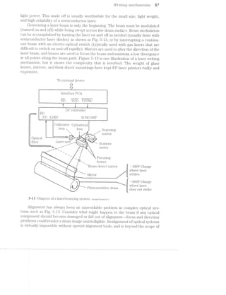
![66 El-6Ci'7”O]3/7,0I§OQ'i"(1]Q/'Zi’ZCI386/'2fl’LOtOQ'@j
this book. Finally, printing speed is limited by the speed of moving parts, and the
rate at which the laser beam can be modulated and moved.
Lhifis
Fortunately, a photosensitive drum is receptive to light from many different
sources. Even light from light-emitting diodes (LEDs) can expose the drum. By fab-
ricating a series of microscopic LEDs into a single scan line as shown in Fig. 5-14, an
LED can be provided for every possible dot in a scan line. For example, the ROHM
JE-30088802 is an LED print bar containing 2,560 microscopic LEDs over 8.53
inches. This number of LEDs equates to 300 dots per inch. Each LED is just
50 >< 65 micrometers (um), and they are spaced 84.6 uni apart.
1 ..
- - LED print bai
@3545‘-mblyer’Y WI
‘V ..!-
": I-I I IN I‘fu'>' ‘ I I
.....EE§E2EEEEEEEEEEEEEiE£E§E%£2EEEEEEEEEEEEEEEEEEEEEEEEEEEEEEEEEEEEEEEEEE£EEE3EE2EEEE..... -F“!-‘F V!fl‘:':¢E:E:E:€:E:::E:::§::§E:§=E:
::::::::::::::::::::::::::::::::::::::::::::::::::::::::::::::::::::::::::::::::::::::::::: II-*' 1' ':1$z?§1:1:-:1:1:1:1:$:$:?:1:-:1:¥:1:1
_ +H-f-O++iH+i+RHi+HH+fH+H+H+H++H+Hfl+H+fl*H1+H+HHi++rH+ *' v.,._._._:<;§:§:§:§:§:§:§:§:3;§:§:§:§:§:§:§:f:§Z:'
5EE:EEEEE:EEEEEEE§EEEEEEE§E£EEEE£E£E5525222532EEEESE535255532EEEEEESEEEEEEEEEEEEEEEEEE
ZIIIICIIZIZIZIIIZZI222312IIZIZIIIIZZIIZIZZIIZ21221212Iiiiliiiililiillii2ZIZZZZIZZ“"‘ .2...'-'-‘1I-I-I-II-I-I~*~Ir‘~>'-2-‘......-.. ...........................................-.---...--...."I-.-"I.-.-“.... .;.;.;.;Z;i;S1.;4-;.;.;.;Z;»;2;.;Z;.$......... .........-......-.-.-...-....-.-‘.....l......................................|.....-1 lib!Il1QlAt:lniAlAQ:llilllillIIDIIIIIIDIIIIIIIIIIIIIIOIDIlIQUIIIlIQI4IllQI:: .,3._-31¢._-_n_-_,_.;._-_>_._._.,._.
.I..........."-......................................IIIIIOIUI OI IO b -Q-...,.-----.......--p---'---v-~44--Q #4I-R5"'I~'|'1'.’-‘-'-'-'|"‘-‘>‘¢‘-‘fif-
.;-<Iq----.--.---.- IIQIIDiIIOIIQOlfilililfiillqilllfiblbllll '.‘.'-'- '-‘-"'.'.'_'.' '-'.'.'_‘-'
I _- or , " ____lndividualP I 1 ___.---—" _ I
- l1 ht beams8
. . . . . . . .. . . .. . . .. . . . . . . .. .. .. . . . . . ,
['1 ' ' ' ' '_'_'_'_ _' '_' - ' ' ' ' ' ' ' ' ' ~ - - - - - - - ~ - - - ' - =r.I':? -‘<I'1‘» ' - .'I'Z‘I':'I'Z{':'I'l'I'H'l':':':v
'I_.:.'_._.:.:._.:.:._.'.‘. . . . . . . ._.__""~'-:-:c;:;:;§¢:;:;§;:;:;§;§|
[.........................‘.I....-.............'.'.'." ..........31.:q-'1:_}C;.;l;.'.-.'.:.;.;.;.;.¢.$.;.;.;.:. S -'1 3
-:-:-:-:-:-:-:-:-:-:-:- :-:-:-:-:-:-:-:-: C31-ll 111L:j:.:‘:.:. ‘-'-.-.4'I ‘l.D‘I'i'D.l.D.l.¥' I 0 I I I I 0 I I I u v I I :':.:.:':‘I.
.:.:.i.:.: :§:§:§:§:§;§:§:§:§:§
‘*' -:
e@==-semiwmn I====-»=I » , %%====== =-=I===.==1 *==="===
-I-I'I'I-Ii E1:=3=:5:1:=Z¢E13!E= ¢=Eil=$1E=§:=:1E=:
2 .1. I .1 .1. .- . -. - .-. ._.;:;:;:;:;:;:;:;:;:_ _:;:;:;:;:;:;.;:;:;-z
.-.- .- .-.-.-.- . 1-1-1- 1- I-1- 5IEIE$EIEI=IE!3E=§!g.+:?E=E=E=€IEi=§=E=%E=5II 4 ~ < v I - . . . . . - .‘~'.P.'.','.' '-‘P.-'4')!-''-'-'-'2'-'-'-‘w
11 - - - - - - - - - ~ - - ~ - -:-:-:-:-:-:1:-:=:-Q:-:<-:-:-v-:-:-:~:-:»:-:-:-:-
.'.'.'.'.'.'.FE:-:5-:5-:-:-:4-:~:-:-:-:-:-:-:1:-:~:-:4-:1? ~— 3 ~ -|» 0 I ~ 0 : u 0 ¢ I I 0 n 1 Q I 'v'u|'lI'c'I'I'I'I‘'o"I"|"I'v'1'I' --
|'._..._._._....._ _ _ . . - . . .'|.;-;.;.;.;.;.;.;.};.;-;.f;.;{;.;{;.;$.;.f Ig
1.; . - .'. '. ' . -. ' .'. ' .' .' '. ' . '.'. '. ' .'*.=:1:E:§:§:?.E:§:§:§:§:§:§:§:§:§:§:§:!:I‘
'._ . . . . . - /. .'.'. | - . | - - ¢ . - 1 ~ - I . I - . - - . . . .:§|2:I:I‘-E::::::::sfI:I:w-_--.-».r-»- . Q - I - . - . . . . . . . . . . - . - - - - - - ¢ . . . I-...._,.;-_._._.._._.,.-_;......... . - . - - - . . . . . . . .. _ ~ , . - | . - - . . - . - - - ---.-..|ub:._fi“|-I ~
5-lit Diagram of an LED print bar in operation.
The operation of an LED print bar such as the one shown in Fig. 5-15 is remarkably
straightforward. An entire series of data bits corresponding to each possible dot in a
horizontal line is shifted into internal digital circuitry within the print bar. Dots that will
be visible are represented by logic 1, and dots that are not visible will remain at logic
0. For a device such as the JE3008SS02, 2,560 bits must be entered for each scan line.
After a complete line of data has been loaded through the DIN (data in) pin, the
LEDs must be fired. This is performed in segments to reduce the power surges that
would be generated if every LED were fired together. The JE3008SS02 is divided
into four segments of 640 dots. A trigger signal (or strobe) can be applied to STR1
through STR4. The signal passes data to driver circuits of each segment. LEDs that
illuminate will discharge latent points on the drum surface. LEDs that do not light
will have no effect. Each strobe is fired sequentially until all four segments have been
strobed. All 2,560 dots can be scanned in under 2.5 milliseconds (ms). The drum is
incremented 1/at of an inch, and a new scan line can be loaded into the print bar.
You can probably see the advantages of an LED print bar system over a laser ap-
proach. There are no moving parts involved in light delivery—-no mirror motor to jam
or wear out. The printer can operate at much higher speeds because it does not have
to overcome the dynamic limitations of moving parts. There is only one focusing lens](https://image.slidesharecdn.com/ozgdplurrtdj8c4ktjrb-signature-f36449d24fae8f28749ba408629a60e09bfd643da03035012a2b233e7710df3e-poli-180806114914/85/Easy-laser-printer-maintenance-and-repair-94-320.jpg)
![Ccmnector A
V
-"DD
Connector B
STR1
STR2
STRS
STR4
LA
GLK
DIN
L-GND
VI/'1"/itmg mac/'2,ct'2'c2xZsms 89
.41. 41-
ii5-* @
Iv-J-
?
_ _ ____ __ ________ __ _4 __ i_ .*._*i:._ ..........._._,.___ 7 M» ___.____.. __, _ _____ ____ _ V V »~;;- _ __;_;_
R
I ________._______,_ ___ __________ . __...........M: 11,, ____, 1, i. ..--...___ all
-'%“
it
5»-l5 Partial schematic of an LED print bar. FIOHM Corporation.
between the print bar and drum. This greatly simplifies the optics assembly, and re-
moves substantial Weight and bulk from the printer. An LED system overcomes al—
most all alignment problems? so a defective assembly can be replaced or aligned
quickly and easily.
L€Ss
A print bar does not necessarily have to generate its own light. Liquid crystal
shutters (LCSs) control the transfer of light from a single fluorescent lamp source to
the drum surface as shown in Fig. 5-16. lnstead of LEDs, an array of individual liquid
crystal shutters is fabricated into a single scan line-—one shutter for every possible
J Fluorescent light
'5' "1 SOl.lI'C€
- " 1 .. 1 . i ' __ '_. . . . . . . . . . ._. ._. ._. . . . . . . . . . . . . . . 31.11“ 11....... . 1 . 1 1 . . 1 1 1 1 . 1 1 . 1 1 . 1 . 1 1 1 1 1 1 1 1.111 ..1..111 .
_..-1'.'.' -.'.*.'.",:;<;;.;:;:;¢:;:;:;:;
_‘.. . .4:;§;:;:;,;;:;:;:;:;:;;;:;;;:;;Q; 7'
.—1 1 —~_———¢+:+—;'——<:_—;;—_<:;—;;__¢;¢;,<;—;:,— _ _ _ ,—_—_—;__,;»_»~_-;_ ;—~ _.;.;1;.;,;-;1;.;,;.;.;1;1;1;1;1;1;.;.; C
..-‘2".'1‘.'1'.‘.'.‘.'1‘.'.'.'.'.'.'.‘.'.'.'.‘.'.'.'.'.'.‘.'.'.'.‘.‘.'.‘.'.‘.‘. . '.‘.‘.'.‘.'.' "-Ii);-5I-Z‘I-I-'~1-I-2-I-I~Z-'+ '-_.1111.111111..1111.1..11.1.1.11.1...11..... 1.1.11115.11-.;.'.;i_'._.5;.;.¢1§.fi{.;.g1§1;1{.g?;.;‘.11-11-1.11111.111».11111111111111111111111 11111,-;i$,_1;-_1;1,;;,1_1_ 1_1_1{1_1_1_1_1_1_1_1,1_1_1_
.-‘: '.>.'4:-.-:~:-:-:-:-:-:-:-:-.-:»:-:~;-.i'~:-:-:-:~:-:-:-:-":-:-:-11‘! 1 1 1 1 1 1 1 1 1 1 1 1 1 1 1 1 1 1 1 1 1 1 1 1 1 1 1 1 1 1 1 1 1 1 1 1 1 1 1 1 1 1 1 1 1 1 {'1'1'1‘1’-‘1'1‘1'1'1'.'1'1‘1‘1'1‘1‘1"1 '1'1'1'1' '1"'1' '1'
" . _ ‘I’ 3.1.3.51:.51}4.1.11’.g1;1g1'.;1{.:.[.;.;1;.‘. '1'.g1-I{.'i;1'I5.
..' .' .'L‘.' .''. .' .'.' .' .'.‘5'. .'‘. .' . .‘I.' .'.' .‘ .'E.“'. .'.'.'‘..‘ .'.' .'.' '..‘.'.' .'3_‘.'.'*. .' .'.' .' .‘ .'.". .' E.' .'E E.' .'E .' .'.*‘..' .'.* E.' .'1‘..' .' .' .'.* .' .' .'.'. . . .. ..... ;:;:g:;:§;:;:;:;E;:§:;:;:;:§:;1;:;:;:;t;s;:;:;,._ ‘¢:-'”-IF’
.-' '”' 5‘
~1I‘"l"!‘?'$1-1
—-T::::::::::T
-'T~.._P““-1 ‘.5:-._ .-Ir--1 ....1 1'1'1'1'i ‘ _%... .11'1'1l 111l ..“'51 '1'1'1'.l .-......A ‘1111l 1.3.... '..‘.’.A 3.1.1.1.3 -1.1.1.0I1,__ 1-""::::::...
"H1-1-i.......::.
""'"“-:-l‘.-':1:-|.l"‘.~.-'.-.-
=
*'$:=:1:1:fi5:j"'N
1-;E==”-2121531555;
I11-§;ZI;"I;'
v<;:}:;:§:;§§:-'
:;:;:_~:;:;:-'- .
1*
1.2ZZZ!IIIIZIIIZZIIIIIII}!{IIIZZIIIZZZZIIII!22212132212121!232121223!Z2!!1!!!Z2Z1!!ZI -2,3232_.v!gigI;C;!;I;1;i;!;Zgi;2;I;Z;2-I5! ' ' _ 14- .,
.2;zzzszazszzzszszas22222222222222zzasszzssaazzsssezszzzs22222222222222a22sseaz2s======= l11Cl1V1LlLl€il Sl1l.1l.l-61 S3' :¢:5:P:?:¢'1:'l:§:§'::§:?:§:§§:§:;7§
g =
5 ; Ke E i
r 1 I 4 5 E 5 - ,
1 _ Focusinglens
lndividual
_ light beams
‘11.11111111111--111111111111111111111.111.111111.11.111.111;1_._.__"1'.§1;1;1;1_.;1;1;._1;1;.;
:1 1 . . . 1 1 1 1 1 . 1 . 1 1 1 1 1 1 1 1 1 1 1 1 . . . 1 1 1 .'. . . 1 .'1‘.‘.'.'..'.'.'.'.'1'.'.‘-'.'.‘.‘-'.'.'.'.'.' ;};.;I§;;§:Z;.;.;._.__'"-'-Z'I;I;I:2;Z;Z;g
1 1 . 1 . 1 1 1 1 1 1 . 1 1 1 1 1 1 . . . . 1 1 . 1 1 1 1 1 1 1 1 1 1 1 1 1 1 1 1 1‘1'1'1'1'1'1'1'1'1 1 1 1 1 1 1 '1-1‘1‘1¢1'r~'1‘1'1'(l'1'1'1/'r1'1‘1'1 — '
- - - ~ - - - - - :55:if:;:§:§‘j'E:i:§q:§:§:>§:=:j'§:§:§§§:}:_.;. 1 -
:;:;:;:;:;:;:;:;:;:;:;:;: .:':;:;:;:;:-I-3-1-1-I-I-2-: -:-:-:-:- :-:-: :-:-:-:-:-:-:-:-:~:- »SC€;l.ll llll€
' ' ' ' ' ' ' ' ' ' ' ' " ' ' " ‘ ' :-:-:-:-:-: z;z;:;z;zs;a_;;:;2;= =;;;z;s;;s;e;;;a;z;z-
I-I~I -1- I -I -Z~ 1-1- I~I-
.'.'.‘1'.'. '.'.'.'.‘.' I~Z'2'I-1'!-I'M-I~ -I-1'?-1'2‘!-I-1'!
:=:?:=:i$:?$:?:3:1: :=:i:i:1:$:§f-$11:
I I I I:: : I: ' . ‘ .'. ‘ . '. " §:§:§:§§:§;§:§;§:§:3$,",1!:§:§:f:Z:Z:1:§:§:E:§:§
- P1 1 -1 .
'1-I33; "IO ZOSEHSI ]lV€.mmWWW$
‘ drum- ;i:----------------------- _- ________7 _ _g_-;"_ ----------------------------------- ____ -,V~,i_-i-_-5as-,'-$:;:;:;g:-:-',-zf
5-is Diagram of an LCS print bar in operation.](https://image.slidesharecdn.com/ozgdplurrtdj8c4ktjrb-signature-f36449d24fae8f28749ba408629a60e09bfd643da03035012a2b233e7710df3e-poli-180806114914/85/Easy-laser-printer-maintenance-and-repair-95-320.jpg)

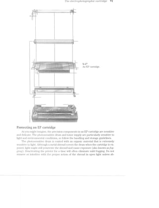
![-1-
.-
rf
EggsP-11
r. 1*-3"’; I
ii l YTEE
-- e
-‘” “ti” 45". ‘Kiri Y! »
1..-‘ ~ ‘,.~., -‘ii ' '1? - - F‘ ...‘;-._‘ V, ~ -'.=,~;, i ' 1&1-i “-~~‘i ~..<'1 ;--V'.~r-. . ..»1=;=1<~ 1-_i‘,_;.~.-.».,
1'“ '1 "'-.i -‘ ".5.-_ 1 ‘- 2 . '---E. WV; :9,5<l ‘>.‘=»i 3/W5 =I£?-_- lag! :‘s'-iii ‘1':<"'» .4'-/2% ‘- qg -:--.<-.- ‘$3; 1 9*‘, s mi»?-s. hi;-. aw ;.--1-1< -"1: am iséiz i Ar
A -R3?» <-.~ "’}~_ -‘ ‘.__ J‘ '7-“=5‘:‘~l=V-'i ,_,._-5+?! ,__,;i~‘ _,,-;~1i=;-., _ --'.*.’-<,j@.‘...- Fa , ,_-7'
.' 4:: _ ..-5%.. .
aE
All electrical and electronic components in your laser printer" (Fig. 6-l), as well as
every other piece of electronic equipment, require electrical energy to function. En-
ergy is always supplied in the form of voltage and current, and there must be ade-
quate amounts of both to ensure the proper operation of each component.
Unfortunately, ac power available in your home, shop, or office, is not directly com-
patible with the components in your printer. As a result, line power must be manip-
ulated and converted into values of voltage and current that are suitable for your
specific equipment. Conversion is the task of a power supplfl/. You will find three
types of power supplies in your laser printer: a dc supply, an ac supply, and a high-
voltage supply.
1 .3. 1' ‘I
' i» > - -M ~‘+ > -‘~ V _4¢@.=rs-> an/s'.~._->-.¢:‘-‘=:=§1='<=i» 2-. ,-‘>.1.<a¢1$-.»F2.-$-531};-§>;:<;-.9;-<,;.;< ;.~.~.;-;»_;.;»;:,»;,-,,»,-.1>§gaV >,.~Q9,.;$<_q5;;.,§~@->m,m>A-cqqmgqn;-===<$ »-;-r~.~:ii»i:-:4-:<-is>@::V:¢:>§$§§>q§ar>&4>-e~;§;"$>;;e§1a<;§s-- -,.~,_'-.>»--4v--<~<~,s-g-:1:-,,£._. .-~,5~,-M:&'%-2=¢-as-:-:¢=-W:-:-;»;=':V=:-1-;< 1.
.—=$.1~.<§g '=1.1;1;>=:=.<;¢=V::=:¢=w¢w=w.<-<5?z‘¢>)>->.r3>@'1i%:r;<=@%§1&=-.-:&~‘z>*{fw$:'-?z* -iii‘-§=»-={-1:"--IV.‘ .-‘; $5 '¢~»’~/>&/A>-=-in-:¢~:¢:;=;:==;==11»;-=::====.<>=.=»:1:'-:1:1-I-f»=='
‘é-*>'r*i1e®.’;‘> =s-Vz.e':1;2.2:-:i;:=:z:s=:===w‘a, Kama?.-.=:V-.~V,==V=s=@=.:;V;V::;==:<s&iY“a*<~- -"-<1; ,>.=rg§.§V» ».= 23*-:1:::i1-"~-‘.3TE'>I--“ff.F>':I>'5.‘r1:':{T1>f'?f‘5**I-I3>?%2?*€5!‘5=5-2‘5$§¥Xs:#9=33?i§;$WE;-4$§>f:'<;‘¥€$/1%1%"El“==I¢XE$iiiifiiilil3EiiEIiI3ii5='i5:I?-’=L‘.11V;1,1ii-~<&=i~,us~Q¢‘ :V¢:¢V-.:.'V-=-V.=;1V'=-¢V=:-sa§==-Q -E *5 ¢>» v »'»:in-r=>$»an:1:22=12'a®»i¥%>%L.->:w>fiL<-*'@=‘@‘*;’~§$*-w¢:¢~1:;-¢:=-=:=:rss»:I:=I==-1:'<=:i»=-:.V..»-3‘-‘X1 ,~ an »:-:-:»>:=_--.==:1-:-1-:-:-¢i>%>, R 9_<-wew-V»4x>@4¢.e>;-=-xii:nswi.-i ¢~§; ; --..;; =;'. v ,"'1I"-'>'-'~_<~?~->):§@Pi=:2=xye7‘;9f‘.X: s~/-.,.;.;.;.»_..,;.,;.;.;,,.;,.;i,,.,up2 ..‘s.i}_,,,g¢.,;.y,<¢.».-.:,.>-.,;.-_;.,,,,;;..;.,.h t ,» ; - . .,. 1- .- ,1 . ; ._ . ,--§-rs.-.-.=.;-W--,.4,-/-‘=-2114>&;‘4-4%‘0';I>112:'=-3-;/,;=;.;:_>;:;;&§/@Q,“QJQ~&»@fi-:£;§sg-rgagisfiziuzfi:q2;;¢5;§:;;E:-1’ ,- - '_ ,_»:}2:§5 “‘*<,-""»»' ~ - (“ ~ » I 1 - .- »- " W-‘* "'§- 4“-4% '33:‘?-Q¥3:5=-I5iI:1:1.=:=.=5-:-.~.-.-
-I1E_?;:;I-2,-,';IgZ;£;£§':1F%<{-'&'€§/ég:4_/§'5.7@§;<-43%$43(iii-Riv-Q)Ii‘f5@;I-I-l+?;J-;;I - V - V$5 Vs .. 1-1» V. .. .§<”€¢'id;»7:-;-:11-155»;-:;1_:;';I
- » '< x_ 2 ,
1'51?-‘S5-'l§¢E?E=E'J‘¢2(§,‘ ."_ 1-=-.-3----Vzai’-.~'.>-w ,1-5.; -1:, V: - r _§_§":v~?~s5::5:>’§"A7'.;»>,~:.:..._ »
£1} sisrsszv,-y.€==.{=i1;.:é=&:=->‘~s ~& -Qz,,.. ~¥=>'<<':a’=i>:>¢'>i:2:='i::2.ai:s:=¥:;=:Vz;Yr=-1 i-1." - -.7.’-3*=fl:.:#~>>.a+-=:»-»»-1;»-":1'.-1 3.:-Y1V"'1“"'V**‘~'*.:.:~- -,‘< “><'"$*i5z""V~'1¢1l"‘1'?""--rw _;_;._~.~,;.;;.- _->~- ~,.. ,. ~. + ('!~',q2"1%.-‘-.p-§,;.;.¢;;=;.;.;.,-1,;;¢,;;_=;; 5-;_ - » 1; -’ -.1:-:I:».'-;T;‘.T:'-'_1r=11-1=:>4:I9:-'-‘+22->:?&:»:»:E-:-ti:¥:21§$§4.,- .‘&‘:=‘§>.-V;'-:I:'-:>_§l’_-"Y
""'1 1‘ " i " 1'-ts Aw =:;:§"~I ;?.V",..*j>‘~,Y/; 3%‘, ~<>g,<_,%‘_,;5;_I;;I5I;a; '.<-V ".1-‘Y avg"‘:I=1£=ErE;E;§$§§;E;£;;§;E;'.~=-(2,-s‘.:¢'=>,''*,;=- <. -,v*i=;".» :§"»-,5’ :11;.-.;~:»;»:¢-1-1-1‘-i ~3»iF§;=:*.=:':'»:i:‘;?:-:2!:‘=f.-I':»;f:I:155-E3.-"-*I1:»'-
; ‘.5-¢ -¢.>>!~§(’{'43§>&~_$§§2<<§¥=@s Q by '._;5;=<,;~;;<<*§*-;~.=>1§'E‘..;-;;; :--;-:.'-;.'.:':r;'-'=-'-.-_:11I'I * Qwé :¢:;::::1.=<'-;:==;=-/::-‘:31333:;1:;3;,$r>;.;:_:;;‘Vz;;;E;
%?.__ ~ ' _ -- ‘-;p|~ AC‘? i .- V. , -»_=;-;-.-_/.s;=.V;~;-;-;-i= »?»I'.‘-I-I-I-1‘ _V~..-.--.V-.'.'V¢¢V
‘fa?,1 3.":-‘1_'I':'"I-':I'1~‘77511‘5‘-E1€i1r.1~V‘.-‘7*‘;r‘ 3"*"'?’--"7103"’ 5%‘ ‘Q=:53""?"*5‘:55’55*553’5 ~ /K 1 . 1 ll N5 Y {N / :V:§_:5-_.
k §§ .
Q‘ )1
/C - . . ;-.>-. 2-,; . < ~.¢-:. 1 - .i1-;1:111;=.=:1:=$.:I;:»r:1'I_1;1:-;=‘.1.--'~:.;a--'1'» .'?'."‘-"":»I-I » ',’ -.5 l:-"1" ‘lb? ' V'V'.' V13! ' ‘Z51255j§§'§:§5I55;'§"S§:§‘5E?
‘~ "-' 1->2 *‘ =1.-1»-§:.;:-." -'--Iii -1'1'.?Vi»':V:-5->IIJ; $3‘ ..-:='3:l‘=’§{'2§='3i5I»§i5»5:5-3'55”
:<*V';;11:Ii:~~i1~1 -‘£111 ~31I=§.535»‘1‘£Pfi:lf.:31~: ~:‘;-* . " -> » * ,,_ __-;»;:;:j=;-»:;q;;;;.VV :1.» ii-.25.-{§,=;;'='-;::;:;=,»;».t..._r! ;»':13.:I~1~' ,;:-5£‘1?£1i1525-‘2i=1i"“'-gr ».':.-1';1'5r115:1:i:?;i:§2i1:r;2a:n::%3 Q"S
.-.->r - ,~--5. ,; ' ‘v ' ' ~ .;;:;:;:-:§¢;;,;::;:;:;:I ./ - V " ' - .3-;:-;;§.4;,>.,;;~.;5».._ .,., , .1 _ . _ _ »r_._1-:5.-j;;::»-.--~ ...», i.1'.¢;z1-»-i;i:».,t-,'.,:==:‘=;;=;~‘~*1?-1:1-=5?:f:2>I:1»;»~
5335 ‘..;.";::» 1V.V~:i:;11i=.c=V=V-.~:-:.... V I - V -.:;:=1::a~.=;:=.1i--1:;_ r¢,v~,vr;*._¢ c is;;;:->;.:.:;;;;;;:;.;:- :,::- .»_ ,- .» :,=-=;:~::¢=:»:;~==/.13,V,-z>;z=¢:§:r;==:. v ~1~: 1 H I.-1.1-1.1:»:~'-11-1' =-‘=2-1-;-;'=-:=1-I: ' -
z =iii‘51‘1‘.‘i*Z*?’ r‘ 3525::EE1E?’15E55‘?53lE?T3¥§‘§*f%é§ ?.='5=‘1**>i=i“="VVV
’.- in‘ f.hfi‘&§}él;g§"¥7§Z1I52¥?:{:"'%i‘§i:'I1:':.¢""*:*»-'-I‘.'?f" f
~..%:3>;_;5‘%§.»; "3 ‘>-53; V‘,-__: .,.._-;;¥-a ,5-V .--;.'--;'f§Q-*/.5?‘ -- ’ "'---**-*'=:;;;4z§;-;_:=;=5¢;;;=5;51;».
" /
1 ' 1.r<-i‘.<§'=>.i;i¢-I-;;¢:;;r=:_~~-,1,-_-1,::.;»-;;»:;;;:. .....-:'1s<-',r;"3"y1:12», V ""1"-'~"'1=11 11-rI:r;.-.-.».».
, ~ I 1'->>.~:'.'¢‘§zrV..E:<=Y‘=¢ ~ -= , ~ ' .. . . ~..¢»s::==:=;;::iV~V;'=.@;=V:V1=:=-1 »§'i~:§¢=;=.-.§.>,=.1;:;§::’;’;';j-1959151-I¢:*;{+:=5<2;;;;j$»;=.I;;:g;};1;s;;;;_;:,;=.;::j»:1_:-j.=.»;1;;r.;;;'.-1.; .1 » » » ' =21-.=’:1:IE:--‘.1>-1--V-;='=i;<=.=I:i<:' -Y -'5?'lL5"'%1‘§?:3l?'?;?§§ 5.} W§Axi$§.~;'1|'l;'j§:,;I_-_-__L‘_.v._ ~= ~ i , 1, -
;-»*¢~*i W
_ . . .V . 1 V - ;-;;.-;;-;.-.»..»;:<»;.- 2-:‘}.’;~_'L-.-
:-wt-.:V:-‘. ~.>-:3 - ., ".3. :_.'.~:;;:;;;._:;;§:;;:;.;._,, -. r ~ -. V- - 1-:-1:.‘-:1"»::»:1»:-;.-.:'»:" ' ‘:>:>=.1-‘<1-In->1 I»
’/__ - 4 3 -" I "~. r r I-~ (Q1?
1 ." -
Qw Qj:15}?XifiI5-:I;E5§{§5E,;§;:2;»;‘3@X:""iV112%;§5;’&=l§L§I5V{5-i1I§5§§' -_;;»;2-15$F'==-ii};§E2§f;E;5j$.€;1=E§E=§;E - _
l‘ '1 1“; M “ "'1-.;:Qz;1;;;:;.;.;=,a_»;»:;1;:,g:;:4;;5:;»:;:;>-_::;::;: j;?}'{.:'.-;:'_'I5II{:5_';'j:'.';';';; ~ ;I--_._ 3.3.5.1:--1:1‘;-,;.;;;:;:';;=;=;1:':V:;-::jV2,>:;:,1:v;:g:;;:;.;»;j-;._;, "-'_:;.;=;;§=_'-:;;3:5:'»:;' :£:3'.{:3=1=j:§=§:}? -‘FE-5£2é2i;!;i>;===I-:I$’; III-'1'-=1‘; ..
i " ‘ ’ ‘U 7%;5I'Z-I'Pb§I'I'?-:'.‘.‘.".*,'1'."'1 : :. }--3:;»:-’¢'.-.=,u>,>.-1-:;=;1-.>'»;1=13-1=5-;»;=;;1:-;:;.;';:,?=j1;I{:==3€PI5551?-E=Z5;I5»E;€-;=E=;?iiZ$=ZE 11>: '1: '§:-5'11 5'=I'§'5?{i:}':'Z1‘V;‘;5E 5 :11-
,_,_ 11;;:$5:1§jS§;§g=;;5;;;g;;:=.='-;=:";§§:1sI:I:'3=§=i:5;1i-:5:1:I;I;{;j;g§:'§:{:$;F; »;-;;.- 1_;:.r;I5.
- »»:-'< ";- -=f»-:==¢=§=§:1-'=»<V...:.=-;.»:-V1.. . ..».;r . ' .. "---*‘-;2E2:1:-i-=;.a-'.2--1£:a%'¢1~1:2; ~~"~-=‘=»»:»r<:a:===-====~:=~:==
bl~ t. ufi . 1 .,» $5‘ ~,~34» . ' '@. A, _ :, .. ,_r.(. A, . . .1 1 .,|,,11, ,. .1 1. .42. ..
745w.’-.s~.'f.1‘ ' $fii“1‘;‘4»‘I_‘¢!.§-1:if{;'i_:¢-_;_ *1’ it-‘->-"'3.‘-‘J,-1i';§-‘E.’--»’»"' I-.1‘--.‘.‘if>'.T=>“1-I'ff-';$f;?:i3°‘i~§=“I:z-151%;-111$’
l~;‘<>:5~;..f$'§-;/ Y-§;‘¢,-‘i»>-_:,:,;~>_;,g;5;» 35*-5* , 3 I=-;»;-.=-;-34;;-;-;.».-;.,.»» 1» -1 *» 2 . '- 1
‘-M‘. ._"»=<~. =1rs» = at .. I *1
'15:1&3N"-'Q5ilU!7§vh1m:@§i'4* x,'}h.=~,>a$&:$:R;1::;s:»>:..i'.=;<-.:s»-i;-;=;-.:>.r--=;';=.»;-rs»-air;---,>..- -, . ‘Fir’/1:-'=s“!i$};.-1&1=-I112-:2-:2:=>:.1;>2»'-.=-fi<“(¢;.a§:2--. .2I.'a=E:».‘-.1.12%%<-.1 .‘" ' -. -¥:3‘i*‘ ‘§>< ‘*§>'-*§>-§~*/‘-‘:»~'=1;~n1¢e>;=I;r¢21=
i,-.131“lI>=il:>*§?;*at=$l%‘§sii§'vX :-?-_- "4-2=¢$§r~j;=;:;;;=r5g;;;;3;;;;;;;g,,;1»1§;.j:-='-I1;-;;»:j:.;:.;.;?I-j;_;;-g»I»I»i.;§;;.is . . <§'a3r;».2:9E;>=411:iniisranrs:I$>=15Q;;>51:1sass;=;=;;ti;>='=.';=;=;'{2-.=;-»=.=-5: 12>->.""‘$1 'F*1-“~Y'>‘§‘5‘,§'&5%{>2Z1$’?>'?é?1»'
' 1%.!-,“-'5,’-"-*>*‘<2>'1§‘-'1;-‘i » — '>I‘r'i-':*‘5"’-"i= i".5-1'3"»"*3"=?§a'L 1 ..>.:-$€?%»:=-'51;=1-;»»‘;E1:':'=-=f
V . _ ._~'_.=-,-. :, _"_.-v_:_»*>,.,-._~3.--1-»~:_ -.,.V»-.,, ~_» ~-..<V-,_.- V ._.- _. 1-1.-1'»-.1..»;:.-=.'.<»--1 ¢-- :-*»1'-<a'-:->-'¢-:- »:. - ' ' ' '
1 fiy
fin
‘ ~¢~5;<"$”‘
onAnerca
¢.}~§~.’=<’";”""'
~ /~ ,;< .., .. .. I . .__._.. .. , __ Y . ,_ -/-»~-.-1-:-:-::.».».» -1 1 . ~ -.
an ' A, ._ ,:§'- 1-‘_rl-:‘:.‘::1'§fv‘)|:Q:"-ll;1l<i1‘J‘: - 2 “ ‘E -;::= ‘I=;1E-E1212¢*E5E§?22E'E:>‘I5111*.f=.*’"'=E='§§ ‘*-€.¢f=%:;<§:z-<:z>;<:=§.i§:;:;:::<?-';==-=-:5--:;:».=s¢:=--Vvri--.-...1..
5; ~ ~ I" '
V ~ . -‘K “‘~“< '>. - sea -~~s-~-.-.i-> 1*-'>‘V>~:-.:-».¢.=.=::.»=.:':~.... :.V.V=->2-=:> ~ »<..»-- ~-.. 1 ~ » ’<~'~
5 . ». V‘$ 5&3 -'7 -.1-' *1‘ ‘ - ‘- ' ;J<3§'.*<.§I;*'v.}=' z'r.'<{‘-'.': ,. V 7“ "I-£>1Q~‘4»E'-T: ifi.‘-§?>,g$If-.I;‘£-5%.‘ . .i i‘l5>§'."€2?~5 El.<l."- .. /V ,‘,¥@>}-1 -" ' ' ’;i’i%>' -‘4'f;»A1 '~,.> ‘xiii -1 ,.-g. -.»,,;£w$§; -' ~ 1-§=."~'4‘~","--1.-,.~'>i'éi A -'“Am1:1:;:.»==::=;s§:'==.==;--'.»;: .»-.<-V-:-s->».»"é>*<!-'-:%-2 -- ' 1 *9
.--?;:==V.->‘ ‘R<;§x'°Q§¥-§<’.§§{.§§:-g{u>i::t€>§;~3;;;§-%<»;,'e({;‘~ ~ -$f"l5-‘)_1%'g~ ' ~’>r{F;<;'.-:-;-;-.1-‘-<<',; »--_-'=;:~:»g»;;55-K.:>:;;;;.-.»;»;n;§a;;-. .(<»;;-.1'?-‘~,>=§'»-;=»:-- =; ~ 1 - 1.2‘. . -1-:i.'.;.»--=7!-»-1.1 *.».I>'
""s¢§/'<>'1§<'~">4strfi-$’§§4;3/--&:<<§,>»t¢%#'-:%-z- ~. '§"3’*'- !¢~1-?y:‘§ V - ."»§<‘-'4 335;;-5;32;:;:§;j:;;3}1§:j:§!:};;:g55
=*.=§?;‘.~*-§¥;"'1r5'>;§,‘>~>*.>‘?a>%§§» ' -5$‘¥1=1‘==*=~"'V~n 'N~4g;-.§;$i;=,*.>:.-;=I-:12»-»»;-=“.» 1» . -1..‘<52-I‘in,/him?)/qééwrr==>:®-:'§p-- --"-:»'-+21‘-;t-=’-3:‘-an
1
* ~,z»a ; ‘I ‘Q 33“, /‘ , gig‘! ‘ *2 v"~~" * 1 i§§_’:_E;;i€;-;}.§':=,a3»§;§:iz‘2j=i.I2':::?>z'&,;,=;;-i>""’“'" ' " r~» ‘“»*-i1'.‘;=..’€V'-@~ -1 Ii " ~'~ ~. ‘ ‘<* :-Z>.== . . -
x
_ ,; * -='_;:~.;3*.» ‘~ ’ - in "1 -l " - ‘"~“~;=i*‘b'-f.""’IE;'§:=
EIJS
The name ]JO‘Z.U6'7” s'u;1.3pZ»y is niisleading. A PS (power supply) does not actually
create power. lnstead, it converts commercially generated ac power into one or
more voltage levels better suited to particular tasks and components. Power supplies
F3](https://image.slidesharecdn.com/ozgdplurrtdj8c4ktjrb-signature-f36449d24fae8f28749ba408629a60e09bfd643da03035012a2b233e7710df3e-poli-180806114914/85/Easy-laser-printer-maintenance-and-repair-99-320.jpg)
![Pow-2?" S'L!,]9pl’Z8S———CtC c1.v'2d liitecm" dc 95
FUSE, Traiisformer
ac output
_w
...“. il~._..l- -|- _.' '-_
""- |=”"'1" 5 ‘I 5 r
1; 1 ‘I Ii J m:'. 2:“ ' I Q 6 a C;
, '-___.‘ I $5“ [ . . 0
-1: ::- Principles oi transformer
/“Tm ‘Z '" -F operation.
/Ean--‘.‘-‘.-
.....,...,.,,.............___-_._-_-
-1....-~
Il_,,'‘I
r/‘ii
J
...-..
II-Hun um“ _=‘
ac input Secondary winding
voltage ‘Solid core
Priinary winding
(metal that can be magnetized). The core serves not only as a physical base, but it is
critical in concentrating magnetic fields around the transformer as well.
An ac voltage (or gpr/zlmcz/ry collage), usually 120 Vac, is applied across the primary
winding of a transformer. Alternating current "voltage will cause current to fluctuate
through the primary winding. in turn, this sets up a varying magnetic force field in the
primary. The core concentrates this magnetic field and helps to transfer magnetic force
to the secondary winding. Note that a solid core is not mandatory—-magnetic coupling
between two coils can occur across an air gap—~but solid cores make coupling much
more eificieiit. This fluctuating magnetic field in the core cuts across the secondary
winding, where it induces a secondary ac voltage between its terminals. Figure 6-3
shows an ac voltmeter measuring this voltage and shows the transibrmer principle.
Voltage across the secondary wii.1ding is directly proportional to the ratio of pri-
mary-to-secondary windings. For example, ii" there are 1,000 turns of wire in the pri-
mary coil and .lOO turns of wire in the secondary coil, the ratio (called tut"?/2.3 'r'ctt'io)
would be l0: l. Because there are fevvser secondary windings than primary windings,
that transformer will be known as a step-ciow/2*z, transformer. If 120 Vac were applied
across the piifimary, its secondary would ideally yield
120 Vac
12 Vac.
1
if the ratio were reversed with 100 primary turns and 1,000 secondary turns, the
transformer would be a l:lO step-up device. An input of 12 Vac to this primary would
result in an output oi’
T 12 Vac
120 Vac k “L
10
across the secondary. An iisolcwivorz. trcmsfo/r"n2.er has a lzl turns ratio--the number
of primary and secondary turns is equal, so secondary voltage will ideally equal pri-
mary voltage.
A tra.nsformer also steps current, but current is stepped in reverse of the voltage
ratio. ll’ voltage is stepped up, current is stepped down by that same ratio, and vice
versa. in this way, power taken from a transformer secondary will roughly equal the
power provided to its primary.](https://image.slidesharecdn.com/ozgdplurrtdj8c4ktjrb-signature-f36449d24fae8f28749ba408629a60e09bfd643da03035012a2b233e7710df3e-poli-180806114914/85/Easy-laser-printer-maintenance-and-repair-101-320.jpg)
![Power S'LLp]3l?l€.‘5---Ct-(3 cmd L/med?" dc 97
A l2.cz.U'-r2.t>r:1.o@, rectifier circuit is shown in Fig. 6-11. lt is the simplest and rnost
straightforward type of rectifier circuit because it only requires one diode. As sec-
ondary ac voltage exceeds the turn-on voltage of the diode (about 0.6 V for a silicon
diode), it begins to conduct current. The current generates an output. that mimics the
positive half of the ac input. if the diode were reversed, its output would be reversed.
The disadvantage of this type of rectifier is that it is inefficient--it only deals with half
of its ac in.put--the other half is basically ignored. The resulting gap between pulses
results in a lower average output and a higher amount of rilpple (ac noise) contained
in the final dc signal. Half-wave rectifiers are rarely used in modern power supplies.
Pulsating dc
_ output voltage
ac input Diode
w’
. i§5§5§5§E§?£?§?§?§?§3 *-§¥33§5§E§EE§?§?§¥§I*
$1, —! . 3., =;=;=;=;=;=;=;=:1:¢:1E1_,_ g E-_=;=;=;r;:;==1¢:===§
»"=-3:2:-is “i "1 1 5. .5 5. ‘
.1.{.'-gr-1.1.1. ‘ ‘ ‘E._.¢_.,.,._._.§ -. .- - -
1:1:I‘:5'37 -:-::;’.~:5:1‘:51,3::-'-:-
21:41 -c;:;:;:515$ ~:-:?:-
—=-. .-=-
i ‘i
. ,
F’
:~:-:- .755535.: - l_.
l‘ransformer
6-4 A half-wave rectifier circuit.
Full.-wcwe rectifiers such as the one shown in Fig. 6-5 offer some substantial
performance advantages over the half-wave design. By using two diodes in the con-
figuration shown, both polarities of the ac secondary voltage input can be rectified
into pulsating dc. Because a diode is at each terminal of the secondary, polaristies at
each diode will be opposite as shown. When the ac signal is positive, the upper diode
conducts, but the lower diode is cut off. When the ac signal becomes negative, the
lower diode conducts, but the upper diode is cut off. One diode is always conduct-
ing, so there are no gaps in the final output signal. Ripple levels are lower and the av-
erage dc output voltage is higher. The disadvantage to a full-wave i;‘ectifier is its
transformer requirement. A center-tapped secondary is needed to provide a ground
reference for the supply, which often takes a larger transformer. Large transformers
are not popular with printe1' designers trying to reduce weight and bulk.
Pulsating dc
output voltage
ac input
signal
.1-. *:F:?:=:?:I:-:-:I:i:l I.-:-:':-:-1-:':1:1.1 *.1:1:-11:15:-:-:1? *.-:-:-:-:-:=:-:-:':I
igiéii E5E3E5i5E;駀5EgE5E5§ figigigigigigigégigigi EiE5':;E5E3EgE;EgE5i;.1§5E5E§E§§5E;5§E3E§§
,1. _:;:;:;: I _, I V :;:;:;:;:;:;:;:;:;:;;§:;:;:;:;:;:5;3:55}:5;:-:;§;;§;;:;:§E:;:;:;:;:;:;:;:;:;:;:§1_
-.-.-1+:-,q "_‘_‘_ | : : i ' ' ' '
: ‘:31P Va. 3 I I
1 1 1
|:¢.~:~:-:-:-. : : ' ' 7. .: 1. .:
§:¥:I:I:3:7:» ' . . ' '. .' '. :vffuf-f¢_vfu_ ,~ 1 - ~ I
_:;f;¢;:;:;:;:;:;._ -._ _.- '. : '. :
.¢E1Er‘~“-5-=~E¢I<E --Y ~-. ' '~ -'
5§$§$l7§1§=:.=§¢? "' "'-"I'I'?I'I'I'I'I'Z'I .| |.
._ _)._ _. ._.'._._. ":._ .3 "
1:1:-:1<1:1:‘¢1:i:I:¥ .' I.
*:i:5.¢:¥:?§1:5:1:I: --II .I—;.¢.;.;.;.1_.;.;.;.; ~ ' ...---.
-:-:-t-:-:-:-:-:»:- .~ '. ...
-:--:-:-:+:-:- - -
3-..J_.
E'._.;~_._._._,_._.'-1
"l‘ransformer D10deg
6-5 A full-wave rectifier circuit.](https://image.slidesharecdn.com/ozgdplurrtdj8c4ktjrb-signature-f36449d24fae8f28749ba408629a60e09bfd643da03035012a2b233e7710df3e-poli-180806114914/85/Easy-laser-printer-maintenance-and-repair-103-320.jpg)
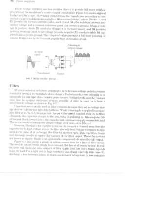
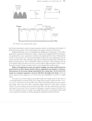
![Wu Po/z.t>e/2*‘ suppl/ales
Bleeder resistor
/ (> 1 l/LO)
I‘ II I} ‘I I] I
__...........4 1‘ In 1. || u‘ 'i____.
.' I I I I I I '
..~|""' *. -.""- ...-1- -. -."“'-_
' . ' . ‘ . ...~.-.-.-.~.~.-.av.-.-.-.-.'.~.-._.. ' . ' . ‘___‘ . _*.. .‘._.;._.._._._._._._.,._._.:_.._..~ >_,. ._. . ___‘:-
.|,~rl"l‘.'- "-"T-. '-E3:t!:1:¢§?:=:Y:3:=:!:1:¥:$§-:1§=:1§!$?1:1 ""-‘."“"~." -.-:1-.,.
:5:-:=:I:=:1:1: 5:?$:?:=:¥:=:l:-:i$:l:=:?:=:1:i$:t=:i$:i .* .-' ¢:i:i:i:1:-:13_.:-:-:':u:.:|:~: :- -_ I‘ -_ ;_ flu:'-:|:':'n:»:n):|:'»:'-"1-}:':1: ._ O. |_ n :":v‘s:::_-I»
-:-:-:-:-:~:»;-:-:-5-; ' . ' . ' . :;:5.E:~;€i§-‘5:-:-:-;~§:;§=:§§-:-:-§1§~;- . ' . ' . ' . -T~??§-:§-:-*.;>:i:-
"1:=:I:l:1:=:¥:¥:I:=:-.. " -' -‘ ..-:~:=:-:=:1:':=::1:=:=§.-.'-$:-:':"“4-i:=:- ~' " -‘ -=:¥:1$:=:fc=:-'=:="
i '-'-:-:-:-:~:~:-:01:-;-‘"'.-.->f'm£-:Z=!€-:-:-:9:-:3:54?-:-:-:-:-'-’?:-'-;-§-§$:=:¢-:=:-:=1'Mr.'r~t'"$3§’*:-;g:<-:-'1:-'1'
'- f*==2=-1:::=;==i=:=:=;=:=::s¢:=r;=::=:2=:=:-=:==-:fi:$:=:=-e532$->=;=:=:1:1:=¢=:2=;=-=;=;=:=$?¢r3=-:s;=§:z-=e1¢‘.‘. . . 4.*_h.J:_.,._.,-_._,_.'.'...I,_.‘. ...._.;._.'._.<.'.._._1_. _.-_ -;.;._. '.._.._.-._:.‘._.','...._¢;..- @ - .
1: _. Z .j . 1. j. o. _+}o;.§-;;;-;:»:~:1:-:-:~:;:;:;:§:;:§:;:;:;:$;:§:§:;:;:g:§i-:’c-5-:1"&';f_g;g¢;.a§|g-a-‘fffff .1. :. :1 / C ElC O1“ 6 — 8
35525252;}325353525255gigigigE;i;i;E;§;5;£;E;E;i;255525335;53551533555355gig}; Discharging a capacitor.
I'I:I:I;I:I:' ' ':fjIjl11:11:11§I:I:IjI:IjIjIjI:Ijljljljljlj III;
r—s4.4.T .~...1
F .'.'- ‘.‘-'-'.'. .‘.‘-‘.'-'.‘.'
i .'.'. '.'.'.'-'- .'.'-'.'.'.'.'H.-__-.-..- . v.-_--.---.--~-.-.-----1
i-I1....--.---‘..>....-..-..-----Q.---|
‘.1,-'-'.'-'.'.'.'-'-'.'...'.'-'-'-'-','.'.'.-»'1'-'.'-'-'-'¢'.'-'--J.‘
-_,......-....-...............--..-‘_-
-_|'.-.---...--.1<-.-44--»-Q-|--;__.
_.i_..-..-........-..........._b_
;|-...-.»-- , - - . - » . - . -Q‘;--i
---‘_;__4_ | - - - . - . --___;___;_|-......-
Regulators
A transformer, rectifier, and filter are the essentials of every linear power supply.
These parts coinbined will successfully convert ac into dc that can drive inost basic
electrical and electronic components. There are several troubles with these simple wt-
re_g'2.z.lctted supplies that make thein undesirable. First, ripple is always present at a fil-
ter output. Under some circumstances, this can cause erratic operation in even the
most forgiving lCs (integrated circuits). Second, output voltage varies with load. While
load is fairly light, this effect might be negligible, but the effects of heavy loads also can
cause unpredictable circuit performance. The filter output must be stabilized to elimi-
nate effects of ripple and loading. Stabilizing the output is the task of a regulator.
Linear regulation is as its naine iniplies—-current flows from the regulator input
to the outputs as shown in Fig. 6~9. Voltage that is supplied to the regulator input
rnust be somewhat higher than the desired output voltage (usually by several volts).
lnteriial circuitry within the regulator manipulates input voltage to produce a steady,
consistent. output level over a fairly wide range of loads and input voltages. If input
voltage drops below some rniniinurn value, the regulator falls out of regulation. In
that case, the output signal follows the input signal-—including ripple.
Filtered dc
Desired dc Regulated do
output voltage
input Output
_. | —___'_‘1 —-. | -~..._
l Regulator "
stage ..____
6--9 Block diagram of a generic regulator.](https://image.slidesharecdn.com/ozgdplurrtdj8c4ktjrb-signature-f36449d24fae8f28749ba408629a60e09bfd643da03035012a2b233e7710df3e-poli-180806114914/85/Easy-laser-printer-maintenance-and-repair-106-320.jpg)
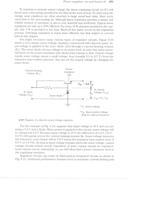
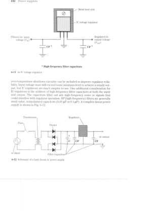
![Trottblesftootmg ac (moi lrlneu/2" dc s2.tppl/zles W3
... ., , .. _ ~»=' , i
i @ @ , ‘t1: is ' ii "111 .':'= F ‘"1: .1 1 ‘x u 3,‘ =~‘ -5.2 "t "U " ‘Y Z.2:1‘. i
~_= , it
Under most circumstances, linear power supplies are reasonably simple and
straightforward to troubleshoot. A sound procedure is to use your voltmeter (or os-
cilloscope) to trace the presence of voltage through the supply. ll’ an output has
failed, start your measurements at the output and work back until you find the ap-
propriate signal again. The following; symptoms and troubleshooting procedures
present more details. ll“ you should determine a power supply to he olefeetiye,
renieniher that it is always aceeptahle to replaee the supply outright.
Syrnptoin i Powe1"stz.].ipl;z) is completely ctedcl. LCLSG7” p’//rlnte/r does not oper-
ate cmd no power /zlnclrlcutors are lit. Before you begin to disassemble the printer,
check to make sure that you are receiving an appropriate amount of ac line voltage
into the power supply. Use your multuneter to measure ac voltage at the wall outlet
powering your printer. Normally, you should read between 105 and 130 Vac (210 to
240 Vac in Europe) for a power supply to operate properly. More or less ac line volt-
age can cause the power supply to malfunction. Exercise extreme eaution when-
eyer measuring ae line voltage levels. Review the hazards of eleetrieity as
discussed in chapter l.
When you determine that an appropriate amount of ac is available at the printer,
the fault probably exists at the printer. Check the printer power switch to be sure
that it is turned on. Even though it sounds silly, this really lS a common oversight.
Next, check the printer main line fuse that is often located closely to the ac line cord
connector. Unplug the printer befo"1"e removing the fuse for examination. You should
find the fusible link intact, but it is not always possible to see the entire link. Use your
multimeter to measure continuity across the fuse. llormally, a working fuse should
read as a short circuit (O Q). if you read infinite resistance, the fuse is defective and
should be replaced. llse caution when replaeing fuses. llse only fuses of the
same rating. lf a new fuse fails immediately when replaced, it suggests serious
failure (such as a short circuit) elsewhere in the power supply or printer. Do not con-
tinue to replace fuses if they continually fail.
lf ac voltage and the fuse is intact, you must disassemble your printer and work
on the power supply. ‘lake all precautions to protest yourself from ae and
high-voltage hazards. Check all connectors and wiring leading to or from the sup-
ply to rule out a broken wire or loose connector.
Turn on printer power and use your multimeter to measure dc output voltage(s)
from the supply. l/lost printed circuit markings will give you some indication of what
voltage should exist at each respective output. A low or nonexistent output indicates a
problem. l/lake sure that the output is not being shorted by its load. Disconnect the
supply from its load and measure its output(s) again. lf your readings climb up to a. nor-
mal level, there nught be a short circuit somewhere in the printer electronics. if read-
ings remain low, you will have to troubleshoot the supply. If you do not have the
inclination or skill to test the supply in more detail, replace the entire supply assembly.
For this procedure, refer to the diagram of Fig. 6-12. if the voltage output is coin-
pletely zero, check for the presence of a dc (low voltage) protection fuse in the out-
put circuit. Some might be normally sized fuses in the power supply, but other fuses
might be installed in the printer electronic control package (EOP). if supply outputs](https://image.slidesharecdn.com/ozgdplurrtdj8c4ktjrb-signature-f36449d24fae8f28749ba408629a60e09bfd643da03035012a2b233e7710df3e-poli-180806114914/85/Easy-laser-printer-maintenance-and-repair-109-320.jpg)
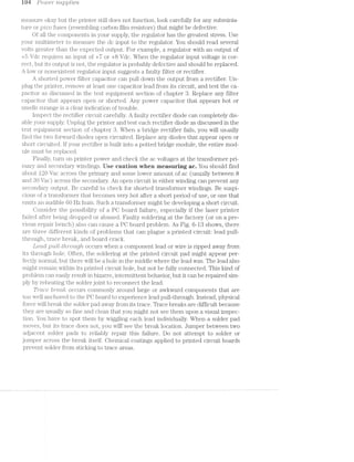
![Tro'u,ble.sl2,ooting ac anal liiteai" olc supplies W5
PG board and
trace cracked
- e&:.~,;.~;.1,<;>,'is,~.>.i'o;>,-».=,=:=
'~‘:'1‘-,~¢~,~<-?;5:,~':‘.<i"-I,$'
e ‘:?%-A-'4'-‘.‘I:'l‘y‘w=.“i‘l‘*,“:"-“>‘:‘1L"“'El, ,_.. . ..
“
,-
ll:_:q:_:;_._:_:_:_:5;____:%::;:_}:_:_._:_(:_:_:$< El | _- iv‘1'w-,'-71.Fh‘<‘.~-".'(v‘~" .
€ J8. 1
gl
XQ C H
l
. ! ..- '-l;v§1‘_‘.¥,i,'l-,LI*§lw,é?*fil
:5:3:-.:5:7:3:'.':-:F:5§3:-. .-:5:§:5:!:5§i:!:1:!:5:-:1: ._ '1 '.-.-.- .-.-.- .v.-1-.-.-.~.'..-i-..-.--.-.-.-.-.-.-.-.-.-.-.. . - -‘ .- ,-=-W5;-;>.
-:-:-§-'-:-:15-2-:»:»:-:-' :-:->:-:-:-:3-:--:-:-:-'-:-:-: -:- ‘,- ‘ll _.-~....-,.., .._.. ...... ..~..._..s..... . fl _..i.-.-.-.-.;.-¢-.-.-.;._.-.;,-.».;,-.-. - - ~- ~ -~‘l it -'i..'.mw-:‘ ' '1'-‘J-'-'-'0.‘I-'19.‘ '.'.' '. .55‘... . J. J '. .' '. it
' ' ' A-2: '<H‘!.‘.‘.'"5'."'.'.I*.‘.'.*.I-'.'§C'.*nIf. ,l_ ‘.~<3
":1:=:$:1:!5'1:1:iziiiziziiizizizlzi-3:1:1:1:1:21:29-: '“ '="tit --.... ......---.~:*¢;:»:-xi:-:4-:-:-:-:-:-:-:-:-$:-:-:-:-:-:-:-t-.-:- W_. — r
l N:-If ;-' :f :n:a'o:|:>:n:-If :-:v:-:-:4:-1.:-:-'¢.1:-:5-'-1s:-: '1 I; »_-.__
3‘-I-'5-2::-2::-'~!:'1;'-'-‘-2$-2-i~:;!-1-I-I--'5'-‘-I-2-‘T'¢'-5 I llll 1: ---___.:Y:;:1:?:-5:-:I:¥:~:1:‘.!:1:=>:1:-:-:-.-:;:-:-995$:-:-:>:¢;§:-: . I ll;1.
=;===>'g.*-s.<-<€$:§?-;g3$$a§;;==3g:=¢;:=g:=;=:;:=:= llall
£1E=53It="IE1E="E§=§fi=E1E==$I3i5I==1=1E1E$1iIE'§E=E$ " .~-'.'<~.*.'§.- . . -. .v.'.v .;,-.-.-. .-.;.~.v.-.-.-.-.' i‘ ‘ ,
l‘;l‘l ‘
I
l l‘
C O 1 e §1"'<-:-:-:':-:-$1:-:-:-:-:-:-:-:-:<-:-':-.-'-:-:-.-:-:-:-:-.-. % it§.
pulled through 3 g PC EH60 bumcd
___ . c i "
eII"_-L-;;—;;;
4:5,...
-- ___ away from board
.__ ..-it:-:= , .
EZ%Il1‘*3Fl*23‘i!§G5il¥tI§§*' ‘ .2-'T~I?""-'i%';' .w£i1i‘¢.. .
‘ ..-" ti.-v.,é.-‘r".l‘=.“».l:":‘1:1‘l~E='-‘“""' .-ljr“ .
l --" .==- - 11:‘
--"' l -T
.. * ' '--._ "-
—__. ._._ ___ 7 V , ;_ . . . _. _ _* 1"‘ =-,=:»i1=§=areii~Wi:‘$‘.2!¢.1<itsWiilmiilliitfiig#111tiijii2.=i1§5§ia;w;=;z3
W .___.,-, 3,,,,._.,;l'T‘5f“T‘Q;;J‘Q1€"FE:§F"§:i: "<:w.-=.r=»;.~,i~
":1-1“~“l'l-4:1-I‘.ii.‘.>"‘,‘v“iC“¥“1$Fi:l '-'%.'.'=£‘-.‘-.‘-r;-. .==.»-1-‘1~:'::
=‘1"»i''3'-‘~*T:I§‘?‘l%{r$¥‘=i.ie=I.1€i.i..~.v.1i3§é;'*=*‘ ‘-“l"“"‘
PC trace fractured
6*-13 Typical failures in PC boards.
Boar/‘d. crac/its accompany such physical traumas as drops or other abuse. im-
pact forces can actually crack the circuit board, which can split any traces that might
run across the crack. Luckily, board cracks are relatively easy to spot. As with trace
breaks, you must jumper between two adjacent solder pads to make a reliable repair.
Sympteni 2 Supply opercmlcm is mte'rm'itte"n,t. Printer" (.)]363?"CtZ§’ZO7’Z, cuts /in
and out along 'z.u'iz§h the supply. Begin by inspecting the ac line voltage powering
your printer. If your line cord is loose at the wall plug or printer, it can play havoc
with printer operation. Use extreme caution when dealing with ac iine voit-=
ages to prevent injuries frem electricai shack. Check the integrity of any ac
connections attached to the printer power supply. Also check the dc output connec-
tors attached to the printer internal circuitry. Tighten or replace any connectors that
appear to be loose.
Check the power supply PC board for any signs of f8.llLlI‘€---@Sp€Cl&lly if the
printer has begun malfunctioning after a drop or other physical abuse. Faulty sol»
dering connections from the factory (or from your workbench) also can cause
printed circuit failures. Review Fig. 6-13 for three typical printed circuit problems.
Lead pull-through is a fault that occurs anywhere a component lead or wire is
soldered into a through hole. Sudden, sharp force applied to the lead can overcome
connection strength and rip the lead right away from its solder joint. Ripping out a
lead might or might not pull the lead from its hole entirely. Trace breaks can happen
anywhere a round solder pad meets a printed trace. Sudden impacts that do not
cause lead pull-through might cause a hairline fracture between the solder pad and
its printed trace. Hairline fractures can be particularly difficult problems because](https://image.slidesharecdn.com/ozgdplurrtdj8c4ktjrb-signature-f36449d24fae8f28749ba408629a60e09bfd643da03035012a2b233e7710df3e-poli-180806114914/85/Easy-laser-printer-maintenance-and-repair-111-320.jpg)
![res Powe2i* supplies
you might not be able to see trace breaks on visual inspection. You might have to wig-
gle each solder pad gently to reveal any trace breaks. Board cracks are fairly obvious
problems, but large cracks can sever many traces--it really depends on the crack
size and board compleirity. Usually, breaks or cracks can be corrected by soldering
jumpers between the solder pads across each defect. Of course, you might decide to
replace the supply outright rather than try to repair PO board probl.ems.
Consider the possibility of thermal intermittents if your printer works fine when
it is first turned on but fails after some period of operation. Often, the printer must
then sit for a time with all power off before it can be used. Test for thermally inter-
mittent components by spraying suspect parts with a liquid refrigerant (available
from almost any electronics parts store or mail-order house).
Begin by e.Xposing the power supply. Apply power and operate the printer until it
fails. Use your multimeter to measure each supply output before AND after it fails, so
you will know which outputs are failing. When you have identified a faulty output,
check its regulator for excessive heat. Never touch live components that might be hot
or carrying high vsol.tages--it is a certain opportunity for injury! lnstead, smell around
the regulator for any trace of smoke or unusually heated air. Spray the regulator with
refrigerant, wait a moment, and recheck your output voltage. lf normal voltage re-
turns temporarily, you have isolated the problem. Replace the faulty regulator. Keep
in mind that you might have to spray a component several times to cool it properly.
Filter components and rectifier diodes are rarely subject to thermal problems.
Transformer windings can open or short due to excessive heat, but only after a long
period of breakdown. Use your multimeter to measure voltages through the remain-
der of the supply to track down any further problems. if your tests are inconciu-
sive, you might decide to replace the supply.
Syrnptoni 3 Laser ,pi"mte'2i"* '21s not O]3€’l"Cll?;'l’lQ properly. ll; might beftmct"lo'it-
’l’l’Z.iQ eri-'"i"ctticu.lly or not at all. Power ’l’l’l~Cl’l-CCll;O7"S 'm’zlgl"2,t or "m/lgltt not be lit. Use your
multimeter to measure the ac line voltage reaching the printer. Under normal cir-
cumstances, you should measure 105 to 130 Vac (some European countries use 210
to 240 Vac). On the average, 120 Vac should be available. If line voltage drops below
1.05 Vac, power supply outputs can begin to fall out of regulation. As a result, printer
circuits might not receive enough voltage or current to ensure proper operation,
which can cause erratic operation that can disable (or even damage) the printer.
High input voltages (over l8O Vac) can force more current into the supply than de-
sirable. Additional current generates heat that can cause premature breakdowns in
the power supply.
Unplug the laser printer and check for any loose connectors or wiring that might
be interrupting circuit operation. The connectors might have been improperly in-
stalled at the factory, or you might have re-installed them incorrectly during a previ-
ous repair effort. Turn on printer power and use your nuiltimeter and measure voltage
at each supply output. lf you locate a defective output, troubleshoot the supply from
its output, back to its transformer as discussed below. lf all supply outputs appear cor-
rect, there might be fault in the printer electronic control package, so troubleshoot
your printer electronics according to the procedures outlined in chapter 9.
lf you detect a faulty supply output, use your multimeter to measure input volt-
age at that regulator. lt should be several volts higher than the expected regulator](https://image.slidesharecdn.com/ozgdplurrtdj8c4ktjrb-signature-f36449d24fae8f28749ba408629a60e09bfd643da03035012a2b233e7710df3e-poli-180806114914/85/Easy-laser-printer-maintenance-and-repair-112-320.jpg)
![Coiistr2.lct"loii cmcl O]3€'7"Cl,l"lO’l’l of dc sii2'itcli..i/mg silpplies l07
output. When a regulator input appears normal, but its output does not, try replac-
ing the regulator. Low regulator input voltage (or no input voltage) might be caused
by a fault in the filter or rectifier stages. Unplug the printer and check your filter ca-
pacitor(s) for open or short circuits as discussed in the test equipment section of
chapter 3. Replace any filter capacitors that appear defective. If the filter capaci-
torts) appear intact, check each rectifier diode. Replace any rectifier diodes that ap-
pear faulty. You also might replace the power supply outright.
Symptom 4 F'll-S’l'l'lQ qilalit;y is ?§'l"Z1l87"7’l/Z»’lf.ll8’l’ll or poor (toner smilclges easily),
or fuse/2"_fa'ils to "reach ope'rat/mg tempeiulim"'e io'2l23/"iiii 60 to J20 secoiiols. Toner
must be heated to about 180°C to bond to paper properly. Normally, voltage supplied
from the ac power supply will allow the quartz lamp to heat. If ac is low or intermittent,
the quartz lamp might not be able to reach or hold its operating temperature. Ideally,
you should be able to run your finger tips across the surface of a printed page without
smudging the page. If the print smudges, the toner is not being heated enough. There
might be several reasons for this. The quartz lamp might be failing, the electronic tem-
perature control. or sensor might be faulty, or the ac supply might be low.
Unplug the printer, expose the ac supply area, and make sure that all connec-
tions are secure. Apply power to the printer and use your voltmeter to measure
the ac voltage being provided to the quartz lamp. Use extreme caution to avoid
receiving an electric shock er a burn from the quartz lamp--remember
that temperatures can approach lS0°C.. The correct ac voltage level will usu-
ally be marked on the transformer output. If voltage is correct, the problem is
probably in the la.mp or temperature control (refer to chapter '7 for more details).
If the ac voltage level is low or absent, measure the ac input that should be ap-
proximately I20 Vac (220 Vac in many European countries). If ac input is low, or
if ac input is correct but ac output is low or absent, replace the ac power module
or transformer.
If the ac supply is absent, the quartz lamp has failed, or the electronic temperature
control or sensor has failed completely, the fuser will not even approach its operating
temperature. This problem will usually result in an error code being displayed on the
laser printer control panel during initialization. Chapter 7 deals with fuser problems in
more detail.
strcti erti
csitci sies
The great disadvantage of linear power supplies is their tremendous waste. At
least half of all power provided to a linear supply is literally thrown away as heat—
most of this waste occurs in a regulator. Ideally, if there were just enough energy
supplied to the regulator to achieve a stable output voltage for any given load, regu-
lator waste could be reduced almost entirely.
Instead of throwing away extra input energy, a switching power supply senses
the output voltage provided to a load, then switches the ac primary (or secondary)
voltage on or off as needed to maintain steady levels. A block diagram of a typical
switching power supply is shown in Fig. 6-I4. There are many configurations possi-](https://image.slidesharecdn.com/ozgdplurrtdj8c4ktjrb-signature-f36449d24fae8f28749ba408629a60e09bfd643da03035012a2b233e7710df3e-poli-180806114914/85/Easy-laser-printer-maintenance-and-repair-113-320.jpg)
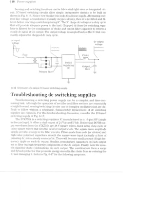
![pws jmzmi fameTroublesfzoot'mQ dc '9/Z/(.2/Zf/£6}?/IZQ7/2/‘_(.7 S'tl,jDpl»’2l6S
1 O Vac
input
as v-ii ea v-1 -.
' 24- V sense -»__
'1, -T. 7 .-.- -_-._____ —_ '-""-
I ‘I 2 ‘ ‘R l
- LIHI g 1"-I it
FIf?u-3 ___;
+
: '12 ~ ' 4
7 _ _ ; /, _:-*' .-..._..._..__
13%-—-i1I1_____l,-~*'-L-'C"—*~| W --.‘ ..- I 11'-'1:--~-L)]* V 5 -----—--~ ‘L 1ir!——i-—~i
‘ i 4‘: Ill ll! .1 “:51 :22:-_ .& AL E1‘ V
13' ‘iii “=3 F srr "Fri i R3 -=31 F. _ _ . . I:I * ' i:r_ llg wg q I ;tfi)3 * _¢= [)€; (J8 ¥ §)9
Ll I l ‘ D4 ()1 IL
m lL 5:1.» .-" ‘ '“" _'. .9‘. _ -
‘Er’; R1 (‘.41.
in _._-‘M W / ‘ I
Parts list ii " M 5 ‘~19
l
....,—,;,..._..gu=.
z
I31 to D6 Rectifier diodes ” Y Output
Surge supressor D ' Sense
Tl T1'ansi’o1'1ne1'
L2,L3, L4 Cliokes
5 ni 10 kfl vi w 5i ) 1
lg; 112, as ~17 id) 1 w 1 3b WC}! | R3. iii _+ +nil .. _.—" - -» - _.
9m¢m9g,:nag--M paan00cf.c-if" P3,-~@—~'Q>~—*
1
.>Ji—‘~J "EE
“J‘J
,§.:.:.w.w../.-.-.»__-_-.»p.=w......11s>sm‘..,_...,.,=;-;7.i-waxes;->:.=-;»;%~»?<_se5ih.¢;='
C»‘O
C"+L23
.._____I
;. K 1 I
:2:'-
égl (_:1. (5000 pr“ , C16 K (37 I
I Q _ W _-
3, U4, U1 OD]. pl?
5, C6, C8 1000 ill?
1 use 3;
ii,5 1 Siwtching re.gr1lat.or El
l STK 7554
6-i7 Schematic of a dual-output, lC-based switching DC power supply.
Syniptein i Power" supply is CJO77'Z];)l63?§€l-§.j dead. Laser" p’}”?i-’l’ZJ}(3’}"‘ does not opera‘-
cite, cmd no power ’Zl’)'Z,CZ’2lCCLZO’l"S are lit. As with linear supplies, check the ac line volt-
age entering the printer before beginning any major repair work. Use your i'i1I.lllI-ll'll€l]€fi“
to measure the ac line voltage available at the wall outlet powering your printer. Else
extreme eautien whenever measuring ac iine "veitage leveis. Review the
hazards er‘ electricity as diseusseei in chapter i. Norinally, you should read be-
tween l.O5 and 130 Vac to ensure proper supply operation. if you find either very
high or low ac voltage, try the printer in an outlet that provides the correct amouiit
of ac voltage. Unusual line voltage levels might dainage your power supply, so pro-
ceed cautiously.
if ac line voltage is normal, suspect the main power fuse at the pi;'in.ter. l/lost
power fuses are accessible ;froin the rear of the printer near the ac line cord, but
some fuses might only be accessible by disassembling the printer. Unplug the printer
and remove the fuse from its holder. You should find the fusible l.inl.< intact, but use
your multimeter to measure continuity across the fuse. A good fuse should 1n.e-asure
as a short circuit (0 Q), and failed fuse will measure as an open circuit (infiiuty).
Replace any failed fuse and re-test the printer. if the fuse continually fails, there is a
serious defect elsewhere within the power supply or other printer circuits. if your
printer has an ac selector switch. that sets the supply for l2O Vac or 2410 Vac opera.-
tion, be sure that switch is in the proper position.
Unplug the printer and disassemble it enough to expose the power supply
clearly. Turn on the printer and measure each dc output with your inultimeter or os-
cilloscope. lf each output measures correctly, then your trouble lies outside the sup~
ply--perhaps in some connector or wiring that provides power tc the printer](https://image.slidesharecdn.com/ozgdplurrtdj8c4ktjrb-signature-f36449d24fae8f28749ba408629a60e09bfd643da03035012a2b233e7710df3e-poli-180806114914/85/Easy-laser-printer-maintenance-and-repair-117-320.jpg)
![i i 2 PO"Z.U€’l" supp/.rzie.s*
electienics package. A low output voltage suggests a problem within the supply it-
self. Oheck each connector and all interconnecting wiring leading to or from the sup-
ply. hik.iii.y switching supplies must be attached to a load for proper switching to
occur. If the load circuit is disconnected from its supply, the voltage signal could shut
down or oscillate wildly.
When supply outputs continue to measure incorrectly with all connectors and
wiring intact, chances are that your problem is inside the supply. With a linear sup-
ply, you begin testing at the output, then work back toward the ac input. For a
switching supply, you should begin testing at the ac input, then work toward the de-
fective output. You could also replace the supply module outright.
Measure the pri.mary ac voltage applied across the transformer. Use extreme
eautien when measuring high-veitage ac. The value should be approximately
1.20 Vac. If voltage has been interrupted in that primary circuit, you will read O Vac.
Oheck the primary circuit for any fault that might interrupt power. l/Ieasure sec-
ondary ac voltage supplying the rectifier stage. It should read higher than the high-
est output voltage that you expect. For the example of Fig. 6-17, the highest
expected dc output is 24 V, so ac secondary voltage should be several volts higher
than this (for example, 28 Va.c). If primary voltage reads correctly and secondary
voltage does not, you might have an open circuit in the primary or secondary trans-
former winding. Replace the transformer or replace the entire supply.
Next, check the preswitched dc voltage supplying the switching IO. Use your
inultimeter or oscilloscope to measure this dc level. You should read approximately
the peak value of whatever secondary ac voltage you just measured. For Fig. 6-17, a
secondary voltage of 28 Vac should yield a dc voltage of about 38 Vdc (28 Vac rms ><
1.414) Vdc. If this voltage is low or nonexistent, unplug the printer and check each
i;'ectifier diode, then inspect the filter capacitor. Oomponent testing techniques are
shown in chapter
Use your oscilloscope to measure each chopped dc output signal. You should
find a high-frequency square wave at each output (20 to 40 kHz) with an amplitude
approxiiiiiately equal to the preswitched dc level (88 to 89 V in this case). Set your
oscilloscope to time base of 5 or 10 us/DIV and start your VOLTS/DIV setting at
IO VOLTS/DIV. Once you have established a clear trace, adjust the time base and
vertical sensitivity to optimize the display.
If you do not read chopped dc output from the switching IO, either the IO is de-
li'ective, or one (or more) of the polarized output filter capacitors might be shorted.
Unplug the printer and inspect each questionable filter capacitor as discussed in
chapter Replace any capacitors that appear shorted. Usually, filter capacitors fail
more readily in switching supplies than in linear supplies because of high-frequency
electrical stress, and the smaller physical size of most switching supply components.
If all filter capacitors check out correctly, replace the switching IO or replace the en-
tire supply. Use care when desoldering the old regulator. Install an IO socket (if pos-
sible) to prevent repeat soldering work, then just plug in the new IO.
Syrnpteni 2. S'z.tp,pl-jg O]J€7"CLZ?lO'7'2.l 'mter'2'r2/ittent. [laser printer operation cuts
ii/22. cmril. out welt/2. the suppllg/. Begin by inspecting the ac line voltage into your
printer. Be sure that the ac line cord is secured properly at the wall outlet and
printer. i/lake sure that the power fuse is installed securely. If the printer comes on](https://image.slidesharecdn.com/ozgdplurrtdj8c4ktjrb-signature-f36449d24fae8f28749ba408629a60e09bfd643da03035012a2b233e7710df3e-poli-180806114914/85/Easy-laser-printer-maintenance-and-repair-118-320.jpg)

![EJ
,1.
,
QHAPTER
s ea1:3, -
¢.»-.'i-*- _~vg-.-.~». c ‘-2+ ..;. . ,.=. = ‘~~ %§§%&._ ,-‘ ‘M -< , . ,.1 J-21-l~~.~ -=§./-3; A *1-u ah g ...’ -.>-*" 1., A 6 ‘Q.-. w ' sag?‘ ~ V . ., ,;;‘?l‘§ h-r "s_ .....:.;,,,_ ,....-.>;:1_.;'._
',=-;i=:§' tsp; 2:4 W - 5:-.;, mi __‘,5 is - lat: ‘ ~ . H W‘, " |,,.;. -<5 ~i‘.;:-_ gm: £45,; =.-...-._ =13; = Rm. .‘-at ,r,*;g <=:<.;=;;‘.;. .},§._*.;‘
'+lt mm we. in-1 1.-Am <.=v .@-.-.»-. aw? - (gag mg N‘ it -Rh .-‘?“ <~ "4? ~ M ms §;g>; ~,~. ’}1:i: +.w*¢»-.s we Jvlllf -v~- ‘..., ‘M ‘...,
l=3~“1'- i»:2~1l {W ‘.~’..~¢ e ‘*5 #“ E -mi ;¢-‘. 4:34 ,3. Late ¢‘$l»- U1? - i Yer; Alt. ‘iv .,.'.§. fie lgsr 4>.;~‘,<_l.1v,. .- ~i>.;‘;::¢q. ‘sag;-. ;»:<>=,. Z-¢:> ‘amma »-::.=- .-MI at >;»-i-.'~ it’-.. we ea tits i..‘i ;<=& as-.-: "jail ‘--me: rs:-.=;i :;;=a'.
‘:13’ ‘ W _l
:3
HY
1111,14 are.
“mg
1*’
As discussed in chapter" £5, electrophotographic (EP) printers (Fig. '7—l) use a coin-
plex combination of light, static electricity, heat, cheinistry, and pressure, all guided
by a coniplex ECP (electronic control package). ’l“here is no single part responsible
for applying print-EP printers use a series oi’ individual assemblies that make up its
IFS (iinage-formation s‘ em). Because EP image forination uses a process rather
than a print head, there are inany more variable conditions that Will affect the ulti-
mate print quality and appearance. You have read abou't how EP printers Work; this
chapter presents detailed explanations and troubleshooting procedures specifically
for EP (LED or laser) printers.
ti; C/3‘ -‘.__?
{A /I
14 °1
.§
>>-I)‘
, 3""1
4
¢f§‘$~/J’
.€/
3‘$5-¢3""»<4'y
Q4:fit
»:a>.?§,-'a
/$2-/>2
‘ER,,/-
»->¢¢¢>,§¢
gaps 1
,._/
2
.,vY%,,~§;4$...»...:?,’;
Q2“
~¢‘/
‘3;*,.<?" .4‘-I;‘
,.
$2 3‘ -'2 ~-0‘ _., V; w 8&5
~ ~ ‘, ‘tr ~"<“ ‘K 3 % 3 :§“<' 0 ~ ~“3(> $51
‘ .. § 6 ~»*” a ‘ (§v~ r ear» ='~<»..~i.’E».:;‘?“‘r‘". ~ ~» '. '
i ' --
1 ". >1 .
i la ."""‘*.';‘1r:.~;-"~’vii--av-?‘*~§* 2.‘ » ' 2,.._:€%:§_~:~51-"iV2~":Iif‘ITI?§I?f$5§§:3:{?r§§"§i:§.zE;i§i" ",' _ _ .- i"-‘ -~';-z ‘_>.;.;,_j_;_'_>~11 .-I "1'1'1:"j'_f§I_I.';_.;=1;.;.'.;.;:.';:-f;-I:{'}'§:;1;:-:_:'='i;.I:j;‘.;="":I:‘;Z-'2‘, , _ - ‘ "" 7*‘-‘=;=“"";"'“
.<<».¢. ,_
_:'{{f7""l"’_¢~/Q’
_,>I//~
is"
Isa???’.§
a K
/.
,, a
,.
awnI<-¢4;» .~»av
,5?’
>)4”
4Q‘?~
Q1»~
ai - Jiv ,3“ =_ A I ';-1 ‘xii 1:? - ‘Q7'-$>;:3./_i%,§,' %.,.¢ . A -$5’
is r »~ r r= a? ea. ,1».4/4,
‘=‘~*<~ ~~ »a‘.a<.a:';’ '!’?‘l -:.¢~i*‘»*f" »<§=;ia<» .. A,_ ~. as .. /'»/;*//“xi,/M. ~;¢.A .~s.,.:., ;.<~<s yt.~..,/>~..a~;.a< “<1:e »~ -is » ~ ¢ ~ <>- "Q ‘a~ee.- ii?-»».~>'>~ >*»> W.fie ...», W»; »s>.. es: ast M . av =>.1>~ §&=¢ ';“V >s=;%» »~ :‘ i /~ — <*~ 4 /ex‘ .;;<-.~;<=‘ ii ~»/ 1 as we ~.* " ~' » -_ 5 : v <»~>‘~» '-is luv» ’ ~/‘w*w1<>‘ $1 ‘1w,s~.=>=‘-ss .9, » .~;;>=> $1 hi; ‘H -‘** 5*» §,,.,<.¢:¢'.>.am-. ia .3,» _ '~§’-Y‘1:"s‘§;:<*§§$¢5‘£<1»" ~._ ,‘ "5 a '*l),,._ "‘ . :.* tag’ 3 _‘7‘~ .,:,-,;.~’j‘~ ‘ ‘ ,‘§‘ I "~ j¢’—‘~, fa
, N .. .. . .. r.. 1 . ./
_ , 2“ {£1/<,':-;:$'§._;-,$g$_{;,-,.-;~..- -: . » - .. »- .,»;;;;.-;.»_...- -. :‘§p3~.',>§> v@ ,
'~ .-> .. ’ *‘ -- ‘ ' . . -_ .2 :>11. . -
>,~,;:_$_m X ,~/I}?!I _. V _v.N_,_.'m_g;é,.;.;.=<....¢ , _ _. €;;ag.§fl.§f @:‘,»
x Q. ~ < 0.» Q. . V Q. ’ Q
3K -.~,~ /4 » >55 .v ,</.0 '~~ I 3"-I/34¢) ,,,.,,.-» -~"“ “N . 7'“
>.<<=~.=~ -l'~‘,§%§<-Jr " ~
9% ‘ ,,§~.§,3§§.§§,.;,¢.y, . I. '-cu,» i ‘fa,-> <
. .v .
wig, l,,°$)>$/Q) t
*'r>Yq/;;>*=;5.. ';>f»""RV
9'/':%<%
.W.
Q'd
is"
1"/~.."?'2,A“if?”
3§
>2».
’/<3“
<-
_ Q ~ 'v- _ ~"~~/.>7..' ~ <x-» . ¢ .»1 . .. 3*-» . . . .. 4. ; ' aw".-‘71:l:_“
' J ~ _ ~ '92» '%>.4=*;;~‘».'§.,§‘9.<$:‘~&>k-$;s‘,,-J5 ¢~fi*§:»_ 1- ' - _ , ¢._.q,,»,¢1atw@,~%‘H;$:.§§¢§$$::;'1'5If-':'I73-'1='-.:1:';'.<;--1»-',v::;:.3§ §('~"t?1'§i§‘~'r‘P;3'
~ is i V
~{ ‘Q .2?,<,~a-fie‘ V V . ..=@iv. =1- V. . ' 1- ~ ‘ ~ s» /‘I"Y ‘-all §,'/-Lk,IQ:5¢;;--¢"/tv‘=15--@’<g§%,1.».'.»I».»----.=»=¢»’£-’ >1‘ “‘E¢T'~L'>}l=Z<&L$§¥Q;~g2§i§€:kq"'=¢@=¥;$,,-('51‘!-wiiiéP“¢:‘i¢P;§s§>i~@*5'»&yI'~. " ‘I;'j;2?1"§f.{:1,1:}Z.i.1j,§.f.§¢j:;§:§:{5§§§1:j::.;"_1|§-13%;?
" ‘ - ~.'&f>43%§>'$’@%<_§¢s:>~121%-imae.;.¢>§~@»=-saz&<<)¥m>§a:§§e s-»-'-1*’: "Q5;$€7>'“‘~:"7i*I‘:‘1-1??!-’=1i:4‘E:=@};</$E¥?'iii)£:¢‘¥~~'-§}}§¢;$1v51.{1Yl'd,§l§>:~.;;>i$m&;Q§g,!* .
i v - V“.tassh;;=#*éss‘>=."*%=I~>1s§k%s§w~'fi><sWwK&%§"€V V "'-=-js;?;5335£_E, :.as;.=.».;.:;< a
»' R . ~ - , , , » , .
' *>
_$¥ ,>»
main?
/ , ,§ _ . , , , .;,;3¢ ...., .... . <..~._@v!».f;s -1' . Q,_~,- ‘._.
. . - - - "z I1‘_;'33’_'-/¢'1)'¢ ",-‘ ‘~*K@.~*‘>; 4.>.'.-.'>>,~- . . v %‘:“’.€€=<.“=' “°‘=‘»TQt!";;¢>~l'2f_"".‘§t=u'fi$'*1; .. 5;.2;5;3_»,;; ;;:_,-,:,;,;.': '-,7
A ' M, ' -;~‘=~<z1-_»» _s,,z,r1 ,~7=.'E:E~*-1'».>'»->2:‘ - . ~. ~* *=»~‘<.’ ' e-.<=» - J 1-M ‘E’i.v>'.‘:~21.'rt’.<t:"~“.~;a§'; ‘Ev-'+*>»':1>.'2#¢1:<w1:"=> :<f-:;z'5-ir{='1E1£.i%:=5; $552‘-5-?»‘&:("M ":~.~@»v“-k-kfé/a={§>~;/.. gQ,~:(.»,-¥<~%»~><».§Ys.z~<‘>*>>-sari.» -» ~ ~ . s, was We -.<>M=.;s~w,:>.m.-.1.->»‘.12.;-¢>m.w~»fi=;;.== _,1.~h‘Q3,,. .. ma -§,-=,<¢.-.@_C§=s§:¢,e3.@@;;$m,_<=_.~=iu24sr§§-;¢;4a<§sW.;_.-_.-,»,: . - . q» :'>~:21$€;,¢:‘§‘34‘?’@Z§§Q=~{;-rg.<‘ria'tlfiiqiiF“:-235-!l;;‘2}:%;i> =».;-.1; .:.»;1,.-;,.»;;<;-.1;-;<-,.;;;.;_'._»;.-.*;<4§<. Q,
’ ~’ . $’€@}$£§;:<<>/saasisifgiz§§§;»@¢<:g~§>w%%;s;§>z1w%$agaszérs1»...~.~-/ ~, ">,-' <w-'.~»s,§>;,>§ ‘seaitsii>;;»:Q&§;a75<i%§m»1::I;:-::.:s:;=:r=:zes~..=.==-Y=~~- > .-~ .
‘I’/11"4"="5$~‘."i3'-'Q‘~'~I>Q/"2§$:If'.-"J1.:.I‘»IQ’wz-‘ . ‘..{<>~¢.‘»;¢.<-§‘a,- -$li1§s$¢<¢>ei-;1:'ss»;:s=s1:=eiag§»gsM» s».-1=<1;:._-... - .
i £3~>I‘-%€‘¢;"'>.-visa’;-< iis - - <“ >‘1'-‘ ta‘?<?;*%<*=¢i;“=W**@*P*7“"‘*‘"="'~* >*’"--in ~/,=_ »~~,§<.,<;+>-éz";<s@~.~§~‘ '§'?<‘}§¢§>‘i¢‘.>/-1%?‘EQ%?:§I$?‘7§5§§(('$@§$?}§}%‘;'::'.:';'.'II-3;‘Z .‘-, I-*‘¢§/-e».a>~.. - {~,§-W; ..,as=1as;;=;;:;.;-.-s.;:.;...eé:%~e--=~. . 4,'-=¢;:';1'~>;2.- <1.~ . » )~/.-=>~A>-v ~._-.‘ -~:N~<~'§_4:¢s’-' is‘ 'Q2>;§~.m‘*$A§3Q;§%_/gg:~:;€>§;;;;;;.;~._~_'_;~ -. ~ . Q, q<§ .‘s¢<..i;.*.-*7‘-tar?-‘Q . . _ »§.;,~§_> 0. <~.~ Q‘ HI
iif 1 ’A{_,,";)~::‘:€'¢%,§<v §*>.=W’:1.k;'-‘-.=»<»f-‘o. ’--5-1:1:-".-K "'(/1-‘-‘--'~.4i-- ~~4<-flv/.< ~ ~vu' ~“»>'.~‘.<‘¢-Lei.‘ ..-.-.__-.-.Y;»>>:.:r-1:-'>';1»:¢:;rr¢r.'»:<;1.r.-1-:1=»=-"" ' .- V ...-.»-~>~<*°» ~ Q _,
~ ~ vi.» ,'~,-_>—%>».%-~r<»§-."."*E-‘ ~'<;$3~./‘».4:=“‘,“*‘:1.‘§ ‘1';“*.'¢<;§;-j‘¥§.1s »:-,:,:;-_:._».-1.--.,;.:: ' .,, ; ,_.;;:.5;s.;!3;';=_;.;;;<;.;';;;;~;-;2-.>.=;=»=.:--='3-_ . _ ~ » »_~».-- *§ - -‘$;,,;.,.>--;-,=,».~_:-;.-=~ .? _'
%~ “ ‘~?~*$>3~~~‘°*"’*1'§*»~~§ :~'>‘“3“°¢"‘< ' *“'*“"‘ 1 “‘’ /~".."';L¢5' »=,"4¢ ,;&<‘ 0/< ~. 1
“.‘- . "1. ¢.'=' ‘I’-‘=1
<<>»:¢..e..-- -"<-z- .: / .. H <1? ..~ xe ‘ - - 7' »-. u ' , 21¢ '. ~ ‘ "’ 9*; .>'>&'=!'/~T.‘>£5‘~"I"':542~‘i7#.~‘€£lI*5=;;.%.=;5~;;.g:r.';;;5»; M v ‘-*;->‘i:-'%5:z<%;£s;;&=é-'-;;-*>=:;=EEi§’€§r=:*‘g»¢*" '$-*.~"* A .92 - F“<?:>'~*§'<:_ . v,:1;-.~-"~:-:=:.1:%=:1=.<:1E';r'::-=§;:r5=.=; 4 Q ' i _~-,.»-‘ G 7 Q - a FL €
§;<>A ,4/ _._.~.~., ,.=s:'?fi;q.:;s%$¢;._=;.;;,;;.:V ~.=;.;~.1;.;.;.§~;;§;z€; ,V L 1 C C 1
Q >. N ./:;Q a, ~ ~ 4¢ » _a _ s 5» >
set‘a
W0:
/I'§'
"»>,,
"fix.<,='§-.,M
i
4>.areah?an
"Q.
"/
f
1/.
,.,_.,W. ., Qis /A. ".4"
. ,
/Ir .:“’-.9‘
e_,,,,/
-. . . , . . . ~ - ~ ~ . . =~ . .~ ~ =.- .>1%==:-:-'s$=§tI"Ea»%.-{=5'112-:1I»:»E=E'5:=:Y:"'i‘ .--"<>‘§§t,¥_,§‘(2 4%, _, <.€.;s<:1'/ €§_‘_~,:i/)2=_-¢<fV§¢,_.,'>_:’_€,1£>~,_ I} ‘_T‘,§- {Q :__._. __ 3_§;,~ %> cg ~{ -/5 s
=~..
Q.,;._,,:¢‘
. Q)
as
<
H‘¢ ,,,<>:*»<:I’
.
a:
.
ca
<
,; I.v
_'T¢’é<"£ 3”‘-,".’;"z//»¢“§’£‘>~z'~' _,
(K
if /<<
rs. § 5?,4.
M . . .>.. -» . »‘»"-§¢~I.". > . ..s=~=. ii .2 > .. . -. ~=~ (4; i**'= -. .
= . M.’ ' ' " ' “ ‘ " ‘,»; Q. Wgga, 3;, ~ _,%f.,.2;‘ ,p,_.?_,,<5,,,,,,‘.=.,W,_ . Bi. J( k C _
-'1} 3 -ins’ .~*/>{»'» ' - ---‘-'"=.>“1‘=-:"""<'.*"*“~ ‘¢§'=;>'.';?‘:':§EY:1';'."i>-'i*i" T ‘ ' ' ’ l '2- »/jag. = ~‘i}{§§»-'I»<_~>'.~’;_~‘$:§»%%/§;!Q¢'»'>>12~}§§}'}‘- - -.‘>>- -:1 _ "5, ,- . ~,:;,a;§a<=e¢.-;:.;~,,.'1;,-.'» , ._ - >.-:=:» =“<' . <"-we - an -1..“ .V-q_’"‘¢y~?‘§:‘¢£*->-$>Z:-.€‘<@*R<'-:'$.$5_'~¢w.$l'%%;;-$~x1rQ~:*» "°5.>./r--:-'r$-.‘ . - ax.;f$§>”*~§f3g@?-1;-22::<>=.=¢:-;=-»;» 1..-»;=;:;-;-:»;:»';-.-;-.;::>;:;=.r;-=1.-I - '.-' ' J:§§@4*§¥‘- 53*“ K * e.-.s»*s§$3:/-94>?‘->!~€‘-.Q,-?‘s%2'&§fi:<>§="§$§§>;>e]>‘*“2<¢’vw§ii¢=->?< ~1i~=i-w::i;:§5~. is M/:1 4. % » - , v“'<.v€,L=: --/4§ .-;;§?I ./Q ':2;.~':£§§-,‘Eats-a‘.;1‘,<; "51R'=.-Q?‘/‘ 3, -4.._~$;§§§, = I;-»v-r J g ;-1:’ ’ 12.,» 4 -' ._
. . - =- w, ' ..=-1 "’J.">.."-.§‘41}§9§>9“2{93'l%%‘:¥$§.(§1'*W> >;u_v .-> ....1~<':-a*.:.f:>»§<".Y<<=-:es~. V avinmyfi Z" Wen
ma-; ?_ -<11 . - ~. <~.$m<s»»§>eaM§$;.,-ss<an..:a;s=eia >'§~~.<.?{":°“ gQ~~~ 1?“? . ~.i.._ -, ~s'¥>».~>:<§-'1°"1@'<.:F*~ M .»"..-@%><<».- . . 1'39». §;~‘:’e>=‘."$»~,-}¢>,,‘-“,'>.’:;'-l:$$:e$411%;:5e:$>~<;s;2r;w;=;, ' sm 59/» 3% 1 who < Q1»
6 ’ ‘ ’"‘ *1}, " ' " ‘ '
.:-'>'
gig;."/,
_._<,wAe-‘.r¢_,w.
-»:_“/‘ma/.§/-.-‘" .'-53'/‘ft-:{/‘;V_
an1.>»
’??”“is
>5§*1‘
2&3? “ta
S
Qlf
1%“
£5lbw
5~
{Q»
f
/.>§z
Q» qy§/% ’“‘<' T 1:‘. =1 ‘I' - , v . ~~ ~= >.~» >, 1 s4 Q * ~<{ . 1-// “‘> .'€5?3E‘,»‘§§3~3555:?555?5i“5>5i?:3‘5"‘5$*<-§é€%=§ 3->":':§ t:1:»9‘P3’1i‘I"'T"."’5ETEw@< ""’*’ ‘ii/i V. . R .~ "‘»*‘*>/>"" /< './V as». es’ '~v»z~»».1/>.;~>'~‘*‘"-"1-Aw ->s>%<~'.<~‘--i ma“-"“‘“ -- w 4*‘. .>.‘<-
‘R %:%"-1.;
i
~/7»
<>,V'
§ » - -».s".:..e.>'- - '~'=' -”.-* -1 . .- -"-<= . <-*<*::=*". 5. ':l§";;¢é11'."::=§1»=.=: s.-,:».<..-.-'T...»-.11:-‘:.<.==..:.»;:..-:.:-a:-4.2:1;=;::¥ii<§,»->£e¢~;; ».,_.
_ ,. . ~ -“aw
. .1.-:-. ~=:- -~ , ‘ ~i '
“§‘<'{.f§""1'§}»§"”*>>>" mi"? 5’:f’-“:Q{.':N- "1‘('~.5.§-M-‘i '$‘ - - ~ 1.=¢»»~ A Wm..- .-....1.-.»;~~. 1.1 r -r ~
it . is _ W» gm
s'=‘'/%.; ii. ".;¢ _' ' _ A », "</1*.-:». 1 >"./~i@? 2 anas;-;.:.§;2sgiizgéf;;=s;==:=:¥:&$>I»&iri;:l:I¥:i~;=5:1=;':¥'='j"-1»:i:=r=“::<.'_., / 9*?-’iI»“».~.~_.»-/'>I’s>I=~.‘.-.-::~ <.‘.-'<:1:=-r.-‘{7-'>,.;>% ?’~ .-we (*.‘»-we. ¥§'5§Q§€§§-"' §~{:*?¢.- n’-R. 'sassI-1*"-:4*z>f>§'<t.¢%§Z§=?r:es;-:>=$»--~=-;:2-11>--*-A-»~:;'>1=.'¢.:;.'.'.r: - 2. -> 1»,-.;,':.+-e. .--.->}.3S=-3;/$1;-.:=?%.~§;--a
~.'-'=-‘=.->.;;-= it i 4. . < . ’§:% _.»_‘!:,§;.;"‘< .,'-;»;.:».t=.=-:..»==:z:::::.:.z;,‘@-=%;%¢4_~¢~%ll! 3’ 5 Q >9; _ _. -~»&'-:35;-.-.'-7; >>.;§.-¢;:.$z;»,*.->;¢.,-- , fig; <3 hgy
.‘-. ->/, »§g < » Q ,_/ M,»
Q" - ’ .. -.»I;:1¢.
I‘ ~»
"s ' -‘/‘>1, M ,_
lag.‘ ‘~1".
;/~
/§"“f,1
‘/»/,y ':4;
rm?
...z£.>0
. .. .. > .._.. ...... . ......-,».~_..»-. -~~ - .. -.~».».»251’-'.T'i_l'i:’-; -.3‘.-’§:i:i:"3: .'-;'»"'i"’:3'. ‘ ‘»_ ":7 I ... 3‘
was / ;— -=..='=¢ =;:.:.¢=z=:11i222:=:2=§:s:;:e¢r=z=s:=:iI=@s:=s2=1&=-.». -11-~=1:.>~ :1"; / - :.:a;i1si>>.=-»~-A...~ .2. ._ -, .. ts “’§‘>*§&-é~ , ;-§;'»§,g2¢;‘~flsséss»-:-1:12::s:=-2==¢s:fi':2i2¢~ris-zéiahna:;r'§s:§Z~::;>1:'.‘5$.:;>i‘;1-.*;¢¢;-M*¢Y’5>_1' i';=:»:I»;.: e.: -- »:. ;=;=:>.=;:;<=:=;.{€<<-‘$*.Z%?.k7fi}3>§§5(
:A $5- = ‘ Ix’ ‘@~,I'£.§Y3‘r(“*}°?43>é>-:1-4<32"?£351?$1191‘£%i-Ef3?~3*11§z1'Z:%=2£15511-1»;I5§E';:i1i<2.'1.11I1-T<:>i1'?YiF-5.?I=s.i-‘£11:-€=E-s==.1*r3:1-Y1-'==~?f»r--‘r='=:--»=1f»>r1-==f=*~l->5-E=;~5’I:E1;1i1E'£$:I“:E:5:£-‘:1 :=:1=:;2=::e:>1<’:’~1* "1 » 2
1 ~. _{}§_ ..<_-;.,<,.._ _ , .;;.,. ,__,‘7. ,1“,-.a ;:._._.i--:;i,- 3‘ . “‘~‘»~ .2’: / >...r._:.¥ »=.=:.=..= »><:=.:=..:+.- .» 2:.:.;<%2=':2?X'~"'§'s ;a>’*‘<',%?§’<;
< . * ~ 1 1 it»'~ Q :_- 3} ,. ----:»;-.=>:-;-:-.-;::»;»:: :»-:-::-:':~:-:~;»:-:-’-'/=-'-:~>:-:-;-~=1~':--’ »
t-$5
.KY1
.MW,_
Q“-5%/av
Ms’’
2/ A_;»§¢
#5?"’”r»>'“
ifs aw ;>-_2
fi"‘»’=~”
’$? a
W
“>3.‘
/'/’:
/ e§3°'3’
W
5>2? i
'2
iM' g"
>~<>,‘
Henet-Pas<ardCo
. w '- - . -- . — .r*t>:r:.==:= ='»=;:5:::z.'=*I 1'»E‘1*?.=“-'i"> ""' %‘.*"‘i‘5?€q"
$4. :§§“§l‘‘§§‘%>@,Kl§f'* “ . ".-:1.»-i1'€».l:.i§1.£=taxi;-Ii’ _
"':=*I#-:i::s:=ira==?swx-P?=’ ~ T " 2> ‘~€~ v§>'*>e¢x ‘ * I ».. ~ t ‘ Q1 » s ”¢ .n.<%§;* .
§’~“"3“§““""‘ .. -4 ‘~gX'-?.,@§; IQs~‘<—
- . _ . . 3- .. I - . .. lE=::-'5';3E3}i’~?;327E:ilEl'2iiE»E3332Z32?I5E351E:IE:i:;Q3:3f;i:E:§E3:5.E:£§;EEl:E:5g;:€E£:~EEEg:§f"$§§"-3‘/:if -<
- ’ = <1; “ '11“-‘ a:2?3a;$~>1;1.:<::1';;.:1.1;;—';-.$1,»-;:»;-.;, ' ' ;g;;;;;;;j:j»;;-355.1gr;1;11;;.;;;;I:;;=:<=;:;;=;=;=; '»;*.1;= 1-r;;:;:>g-1-';=-5-’ >,1:'.;_>. ...; > *~.¢‘>=I ‘=-§"*5:I;1E=;I;I:»'=""15-E2-=:3E='é'E!;= EI;1;i»'=i=E=i=;=; ~ :»:—;~» 1_£;.;; '~?.z-‘{;'3»"!"»~'-.4‘¢<‘
. -'
gs.»-;:32;as;;z;=.:=.:i;;;:%&:==2~$‘v=1~:~'-t..:=;:;22 r:‘1."':»-1.1.;;.-:>§*;;§<.‘# 4-p .~ '=»>.-l;=i’¥=.s=-Ei:<.~..-e., -‘ <‘-=~‘ - .=:1'<=-.'»>_‘._ . -~.-.<i.-..~.w.:1:5-saw.-,t ;,-,-..’1-§_i:¢:=,:a-._=1;»s.:-:=rma=.: a $2-,,>Z~. i<~§ , , - ~ ~<- §~&>> <;y1/:..»/-:»&-- -,,-~..;-’.-»- »4;"~ 5-~--»<w.~--I.-cc? . ~ M,->
_ ., .,
1, .. -3. ._ ;:-:>.—,-‘I.i_<.1.;?5;,j.:' " -..:- ,3 .- . . . _. -. -. ;, ~¢,l,.,,;,,,;;,,- ,_.,._(,,;_¢Q<-,,‘_¢
'=. - - - '-‘J'4i"~‘—5i'- ---~~~¢=‘=¢1+:>.@'~a~.1>='-> . . '— .1‘->"E'I‘J';1I{.51-»:-.=?E1'11:ii12=211-;¢i3;€rE2=3;1EI1{E::=;=iks;.. . .»-@..:;:-f.<:= M" . ‘/~ -va ‘s. >'". -;<?:' -'-'-T-='*‘<’1‘@:“¢">‘¢-=.~§*».-»..&:_.R__ _-» .“P.'=§¢Tall!“.-*:iJ)*<"7;fl:w'-v‘§‘l;.$$J‘(' .», ,.-.,»__. ,l 4" , _Q<»}> ,1‘/44., ¢'..,,g>_,._., , -¢~>._..»;.;_.¢-., 5 >.Y-é,~., ,4;
:5_ _,.- 9.; 4 >;":-_:i~,~-M,-11-.»1_»1-‘-' .~. -.,i: -»~,‘-;~;<§,.*.-:;';.;_-~.1._ .,. - . .-g.4:;>;»;;:;;-;;:=.;;»;»:;:-,1¢;»;»;;;:<¢,»»;-;-:,~;;;=,- .,_._,.,,i.~;.1,;'.,-. <» _ _z ,_,_2<-~ _;>.¥_-* ~»,$:=,_K, .., rs .», §$;.(.,».,_._=._=_-,_§;,...
i =- .- s ' ‘ ‘ 1. ¢»- ~Z 4-‘:11’ 2211* .' ‘ » » 1. .I"’“— ~‘»;<~**¢~- . .=-
.“-‘M <?’**i’§*s >~t§.>i'**v - /r..~i §"'s=*@“s£*.gv§*Q“ <<~‘>,-s‘>§¢>‘§%?““1~<%*¢ has = 6“‘(~§;)v1>,:“'‘ Y; '
q . . ~. 1. , .~. - "-+:-" s- v . », - ‘ -. "- " ~ 7- " _. '- -"*1: ‘ U --=-031,- ' <-' 1 '- F‘
. - .~'»?~~.-=»**" A /3;*~‘>a'=.>:-:'=r<= M‘ " < <.'*’“z.3_ .'§~"~*-Y >1-§'~,3<"§§‘§-">§*%T¢.§?» - “Zia-~>w t..‘*€ - >. .' if.-. 3.‘
- .-.~~<:_.._-*~;_..._~-is, . a-=_, -. I - ,>,.,¢;; . I _‘ V4,“). V; .__;<_¢.,_7.¢,_;,.-is-.1 .iv._,~, , , ._,h._;»; . ». V ': Y». ¢,=; ., 4;" * - -- -:*
its i ~. . "
.;- ‘E-w-.,~-*1.-.2%-»;,, am = L: ’ “I1 # '_~>:*§'v.1_‘_;¢>~»2'-‘*“ 3%.» ‘ <5 Q??? »? )%¥," es» @~ ’ ‘”>' " "V-‘?El‘.“ - . .
Mo](https://image.slidesharecdn.com/ozgdplurrtdj8c4ktjrb-signature-f36449d24fae8f28749ba408629a60e09bfd643da03035012a2b233e7710df3e-poli-180806114914/85/Easy-laser-printer-maintenance-and-repair-122-320.jpg)
![.92. stem start-'2.¢, 9 .9i"oble'ms 1 l7J
Your printer IFS (image-formation system) is composed of eight major compo-
nents as shown in Fig. 7-2: a photosensitive drum and developer assembly, cleaning
blade, erase lamps, a primary corona assembly, a writing mechanism (a laser beam
or LED array), transfer corona, static eliminator teeth, and a fusing assembly. Each
element has to work properly to produce high-quality print. When a fault occurs in
any of these areas, the resulting print will be adversely affected.
Writing
mechanism
Primary corona it
_ , Photosensitive drum
Erase lamps
...-' i
'.,.; i / Developer roller
‘—'HW-i-um": ,1 l"._.."|"'|l' _l'Fl§:'-'.;.;.j.E5l"."Z;rn,. :_, ----_- » .._.
. ‘i J -1 ".'.'.'.' -5.1.1 .3.-.11-.'.".;.{.__ _--" WWW M
‘- -'--==i=.-=:-.-=i=‘="":'.'i :='-'=~='~'2=:=z=z=;==-=== ’" ~
l K Fmlel .
-===§=-“' .-I-I-I-I-I-I-I-I-I-I-I-I-I-I-.";Ef'§;E§:= ,__
‘ *"§5:§§i§4?:3:3:3:3:13313:?:3:3:3:3:3:1:3:3:3:?%§§iE§f* ..=:a="’”-:‘f:-Fir-rz”-“I‘i'é':z:¢.. . iii
‘:::t :I:I',3"‘ "'3,'I:I:I:I:I:I:I:I: |?.:I:I:I;.3**"*,"I:I:I: "][""7.':j'._->:="i'i_'i':“ti‘f§‘j'LIvj..i]°§f1_f'if;-,;I§‘[‘f'jfj1f_}fj‘i
i _[j.j.j.
-1.,‘ . . . - . - . .'-_ .'. - . . . . . . . .;.;.: . . . .'-J . . - - ‘.-*,.~‘v,1'_,- .-" ‘__"_-"_.'V.","_."‘ ‘
>I§§§E§E5!§-I-EI-1'1'1':-P1-I-I-1'1-I-I-I-I-I-;,!§§§§§§E§i “=:;:-,'_-I~I-I~I-I~I-l:;:- fff.7l;f'.<- Tjfi’
_.,-—__ _‘= V W“ -'--;:;;;:' I’,~_'_'_'_'_'_'_‘,*_-,-_ ~;»-:;:'-;." . _;>‘ -' .~ ' .»,,.-_ ‘
§ E4 ! w» ;i
.~*-En»-.
2, e J *1‘
Fmmg Toners Transfer corona.
Static eh'1ninator
7-2 Components of an image-formation system.
ystestrt rues
EP printers perform a self-test on start up to ensure that the ECP is active and
responding normally. The self-test also checks communication between the printer
and host computer. After the self-test is passed, the fusing assembly must reach up-
wards of 180°C within 90 seconds. When a self-test and warm up occur normally, the
printer is generally ready to operate as long as paper and toner are detected. Unfor-
tunately, printer start ups are not always so smooth. This part of the chapter details
the symptoms and solutions for the most perplexing start-up problems.
§yinptein i Notlrmg ltctppens wlten power" is tw»/‘*2/teci on. You should hear
the printer respond as soon as power is turned on. You should see a power indicator
on the control panel (alphanumeric displays will typically indicate a self-test). You
also should hear and feel the printer cooling fan(s) in operation. lf the printer re-
mains dead, there is probably trouble with the ac power. Check the ac line cord for
proper connection with the printer and wall outlet. Also check the printer main ac
fuse. When the ac and fuse check properly, there is probably a problem with the
printer power supply. Refer to chapter 6 for power-supply troubleshooting.](https://image.slidesharecdn.com/ozgdplurrtdj8c4ktjrb-signature-f36449d24fae8f28749ba408629a60e09bfd643da03035012a2b233e7710df3e-poli-180806114914/85/Easy-laser-printer-maintenance-and-repair-123-320.jpg)
![LCL-.S'€’}"—CZ6’t’Zl"L)€'7”y problems i W
§yi"riprorn A l”o'2.t see oi/2t"2.erri'o1-/‘Izliitrjitzlc?cz,Zi/my con'mtt.m-11ccttrlon ]§)7~"‘Ot)t€'l7’Z,-3 between
the ]9'?"i"'Z:’}7,[€"i"" Cl/l”tCt GO’?‘7?.]j)’2.tfie??? The printer and computer are not coinmunicating prop-
erly. This symptom is typical in serial coinmunication setups when baud rates or ser-
ial transfer protocols do not match exactly (refer to chapter 9 for detailed information
on serial communication and transfer protocols). Check your serial cominunication
cable first. l/lake sure that the cable is installed properly. Also make sure that it is the
correct type and is wired properly for your printer. Keep in mind that pins 2 and 3 on
the printer cable might need to be reversed for proper operation. If the pins must be
reversed, use rmll modem (available from almost any consumer electronics store)
on the printer end of the cable. Also be aware of the cable length. Serial communica-
tion cables are typically limited to lb meters (50 feet) , and Centronics (parallel) ca-
bles are limited to Z3 meters (l0 feet). Try a shorter cable if necessary.
There are five conuminication para.m.eters that must match between the host
computer and printer: stoyrt bits, stop bits, data bits, jQCt7"’Z-[Q type, and bcruol rate. lf
any one of these parameters do not match, communication will not take place. At the
printer end, there are usually DIP switch settings or control-panel key sequences
that define each parameter (you might need to refer to the users manual for your
printer to determine how each para.meter is set). At the computer end, you can usu-
ally set conununication parameters directly through the application software that is
doin.g the printing. Change parameters if necessary to set both printer and computer
to the same parameters. Reboot the printer and computer.
Check to make sure that both the printer and computer are using the same ser-
ial flow control. Flow control is importaiit because the host computer often must
wait for the printer to catch up. XON/XOFF (software) and DTR/DSR (hardware)
flow control are typically used. Adjust the printer or computer so that both use the
same transfer protocol. Reboot the printer" and computer.
If the printer still fails to operate (and you are certain that the computer is com-
municating properly), the conuiiunications port is probably defective. Try replacing
the EC]? or interface module.
@ T
355, rf 9‘! "iii ‘ff "‘ xii “.5 1?.
*.-':,,.,» "{‘(,N. :2 ‘.- ;.~ V1 v 8/ T 1'?Q Qiffi EQQE @:[I1§“'
Once the photosensitive drum gets a uniform electi;'ical charge from the primary
corona, a laten.t image is written to the drum surface. Writing is accomplished by dis-
charging desired points along the drum surface with directed light. The classical
method of writing is to scan a laser beam across the drum surface as shown in Fig.
7-3. This process is where the term lCLS(~3'?"‘ pr"2L'i'tter' comes from. The laser beam orig-
inates at a single stationary point in the printer, and is directed at a hexagonal mir-
ror that is rotated at high speed. As mirror rotates, the laser beam is directed (or
scrcz./mi2.<2cZ_) through a compensating lens and across the drum surface. By turning the
laser beam on and off corresponding to the presence or absence of dots along any
one scan line, the desired bit image is written one line at a. time. Typical laser print-
ers can turn the laser on or off 300 times in any inch of scan line. When a scan line is
completed, the drum rotates V.-at inch, and the next scan line begins. This process de-
termines the printer overall resolution (SOO >< 800 dpi in this example).](https://image.slidesharecdn.com/ozgdplurrtdj8c4ktjrb-signature-f36449d24fae8f28749ba408629a60e09bfd643da03035012a2b233e7710df3e-poli-180806114914/85/Easy-laser-printer-maintenance-and-repair-125-320.jpg)
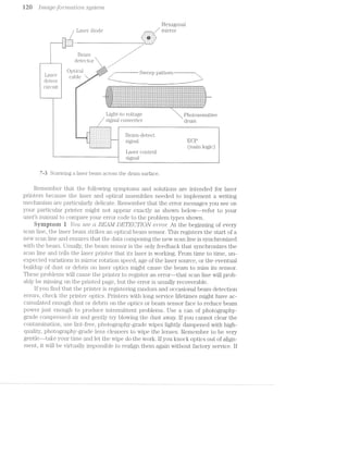
![LCtS6’}’°-Cl€t‘Zl’tJ€?"@] ]_9’}"Ob[€’l7’2.-.5‘ Ii2;i
you mark the lens, it will be permanent, and you will need to have the lens replaced
and realigned.
if the optics look good, the laser source might be failuig. Older laser printers use a
small, gas-filled helium-neon la.ser to produce the beam. With time, the helium-neon
gas will escape and laser power will fall off. lf the gas has escaped, the laser will have
to be replaced and realigned (which requii'es factory service). l/lost current laser print-
ers use solid-state laser diodes as the laser source. The semiconductor laser is coin-
bined with. some switching and control circuitry and incorporated into a laser assembly
with the scanning mirror and scanner motor as shown in Fig. '7-4». This assembly is
called the L/S laser scanning assembly. Because the L/S assembly is completely pre-
fabricated and designed as a replaceable component, it can be replaced outright with
little risk of alignment problems.
Fiberoptic Fib@1'@.l3l?i<3
,, SCREW cable cable .
7 I ‘V PW’ "Vt J7 H 4' Screvv
U ___ A u’ A A A’ Laser driver - “ , Q
Q F‘. , Q ll. ‘ ‘ (Under »l D :j ii 11 L 1 J M_ ,-
. i:.~::::Y-1, my y; . £1001‘ " l
//Qw "Pi N H i l Jrlrl if [
'l°’¢:-._-.~:_'iIL‘ ‘A ‘ » 1 it P V In
A, I i, X Door sci €V
Q
at
-_.;L7{Ear I
"» w"4
tan :7
I
L
7-ii An installed laser/scanning assembly. Hewlett-Pacl<a:'dCo.
Use EXTREME cautien whenever weriting with laser beams. Although
the beam is invisible to the human eye and contains only a few milliwatts (mW) of
power, looking directly at the beam (or reflections of the beam from other objects)
can cause eye injury. Refer to warnings listed on the laser/scaniiing assembly for spe-
cific instructions.
Byrnptorn 2 Yott see ct BEAM LOST e'nro'r: Although intermittent beam loss
might result in a recoverable beam detection error, a prolonged loss of the laser
beam (more than two seconds) will result in a more severe printer fault. There
are many possible causes of laser loss. Begin by checking each voltage at the dc
power supply. l/lost supplies mark their output levels, so you can check each out-
put with a multimeter. lf any dc level is low or absent, you can troubleshoot the
supply as shown in chapter 6, or replace the dc supply outright. Check all con-
nectors between the laser/scanning assembly and the printer to be sure that each
is seated properly. Pay particular attention to the fiberoptic cable running from
the L/S assembly to the ECP. This cable is the one that carries laser light to the](https://image.slidesharecdn.com/ozgdplurrtdj8c4ktjrb-signature-f36449d24fae8f28749ba408629a60e09bfd643da03035012a2b233e7710df3e-poli-180806114914/85/Easy-laser-printer-maintenance-and-repair-127-320.jpg)
![1 A..‘+ 1 //titty cf) (J) “I I‘Z.=(-L-Z.-FL-()"l A 511.51.-er’)'H.~
bulb itself. lf you read an open circuit, replace the quartz lamp (or the entire fus-
ing assembly). Be sure to secure any disconnected wires.
lf the printer still does not reach its desired temperature, or continuously opens
the thermal switch, there is probably a fault in the ECP. Try replacing the ECP. lf you
wish to troubleshoot the BOP, refer to chapter 8 for a discussion of sensors, or chap-
ter 9 for detailed information about the ECP.
m
"léi "‘i¥l 1-‘ F‘=fz not ‘s. "'1‘ 1 "i>l =4: :-:' ‘ii “1‘»- if
-4
A5 -2-‘ '§- ‘*1:-_ m ‘_'2;§_:1< "i, ~' as , lt. .5’ ii I»‘:1,_=‘ "=: ‘r. *' rs‘. gr», In
There are many variables at work in the formation of an electrophotographic
image, so even though the printer might be operating within safe limits where no
error messages are generated, the printed image might not be formed properly.
Although print quality is always a subjective decision, there are certain. physical
characteristics in EP printing that signal trouble in image formation. lt is virtually
impossible to define every possible image formation problem, but this part of the
chapter illustrates a broad range of basic: symptoms that can tell you where to
look for trouble.
Syniptoni i Pages are co/mpletel_y bide/red out, and might 6L]J]D(3CI/I" blotc/red
w/W2. can ‘Ll/l"Z-Cl(3fZ:7‘Z(:?Cl fDO’l"Cl'.-67"‘ (Fig. '7-6). Unplug the printer, remove the EP car-
tridge, and examine its primary corona wire. Remember from chapter 5 that apri-
mary corona applies an even charge across a drum surface. This charge readily
repels toner--except at those points exposed to light by the writing mechanism
that attract; toner. A failure in the pi.'imary corona will prevent charge develop-
ment on the drum. As a result, the entire drum surface will attract toner (even if
your writing mechanism works perfectly). lf the entire surface attracts toner, the
image will be totally black. lf you find a broken or fouled corona wire, clean the
wire or replace the EP cartridge.
7-6
Printed page is blacked out.](https://image.slidesharecdn.com/ozgdplurrtdj8c4ktjrb-signature-f36449d24fae8f28749ba408629a60e09bfd643da03035012a2b233e7710df3e-poli-180806114914/85/Easy-laser-printer-maintenance-and-repair-130-320.jpg)
![H6 [marge-joiii‘/mar.r2lo'i"2. ,S”§,/Sf€’}‘7t'2.»
completely, then inspect all wiring and connections at the transfer" corona. lf the
monofilament line encircling the transfer corona is damaged, replace the transfer
corona assembly, or attempt to rethread the monofilament line. lf faint images per-
sist, repair or replace the high-voltage power supply assembly.
Finally, check the drum ground contacts to be sure that they are secure. Dirty or
damaged ground contacts will not readily allow exposed drum areas to discharge. As
a result, very little toner will be attracted and only faint images will result.
Syniptoni 3 P'2*"Z/m appears speclrled ("Fiig 7-8). Your first step should be to
turn off printer power and check the cleaning pad on the fusing roller. A pad that is
old or worn will not wipe the roller properly and should be replaced. Replace the
cleaning pad if necessary and re-test the printer.
__ _ ~ .. ___? W. .,
— '--*..'=‘.=.-'~'.='
1 -ii} *1-~ 15%". '- -
l~.'-~.--'=-'.-:-: -:
' priri1:. a}:|pes-.1" ;~_ijri,=ai"l=;e|:l
,, .'=~',‘i§-§F'i‘1’:=*1§}IHE=1Z1l=I.1rErI1. Thli-1» ‘$.55-5~ -1211711-»L—'=I"i
l.-.-:1 ',‘_-‘;_§.f.'.’. _ _ ' l
l-'.?';I_',‘1:1“;“;='.}:1!I,ii-‘_i_'.?!.§f.‘ 1321 jfl_§]§IlI'CI]?I11EI'.['.L 111 ii-11E!
.~._ .: :5 ;_ .,_." T
, n|'- '4' ;:. ‘:_C;:'_1.'i _ |_‘ ' ' l
1*-
rl .- . |
" -'1. .._-:-_-"7 l
.‘.-9».¢.=:-'.-~»=,- ."J _: ; ;-_'-_ _ ‘¢ .
ll-1'11? |II].iI'1fifiI'l.i;~§lEé].lg,. }ZI=f1.II3.
t.l1s~. l".Ll:_-'!i§i'l:-lI“l§§i:"':'§“1:I11F::1I'. 7,3
-t'~?L.§'1%;?E;».-, ' , . .
":§"._I-,i,j_.=.;j;j_1i:,iS- 1 The print has a speckled or dirty
I'EiIII11f4.¥IIlI'.L lI-l".Ul‘- 1111513.1111'}.5% ii appg31111]C@_
. l= ~ |-r:'l I
- __ - .. - _ -
. . -. . . 1- -‘ - - '- 0 -- - _-_ . .- -I; I’; _ - l-- -1
- -'.:' .:'-f="=‘. '
_,_';i;';.::_1_t-;L,§§i_f'*';,.r‘ »::1e=ar'i1i'i;e; the l“i»E+e1."i2;1'r*.i;;.=.~;1 ‘| ‘f ‘II I "‘ ' "- ' _ ' nun
C‘
=a:5::z:s:i"ril:1l§,.r ii r-.-*-wit.‘ for
lij“-_11-3:§=*;i;.§.,§*I§ ‘YIE1 ¥.1I'ii1Z- if-I13 Iitiiwill.HH:
.'-:*.
, .'_‘-f$"_-v;a‘_:.f‘ 1;:
...'.S_..';Ljr_-‘. * _ ‘ .
1' ~a:.i-.:~.'-- *--. 1 1-. _ .. _ '_|1_|_t,J‘__*...'~ _ .
-l'.|F.‘ |:',.__ - ,
..-_ - .~| 4. .
1.1.-'.J“"’I~‘:". I. ~
. ' ..'1"' I
.'..—_--3.', ." “ u
, ll. .
lf the cleaning pad checks out, speckled print is probably the result of a fault in
your primary corona grid. A grid is essentially a fine wire mesh between the primary
corona and drum surface. A constant voltage applied across the grid serves to regu-
late the charge applied to the drum to establish a more consistent charge distribu-
tion. Grid failure will allow much higher charge levels to be applied unevenly. The
higher charge results in dark splotches in the print. Because the primary grid as-
sembly is part of the EP cartridge, replace the EP cartridge and re-test the printer.
If speckled print persists, repair or replace the high.-voltage power supply assembly.
Syinptnin d There are one or ni?,o'2"e ’LP€7”fi?lCCtZ¢ w/mite st¢"ec1,l»;'s "(in the prmt (Fig.
7-9). Begin by checking your toner level. Toner might be distributed unevenly along
the cartridge length. Unplug the printer, remove the EP cartridge, and redistribute
the toner. Follow your manufacturer‘s recommendations when handling the EP car-
tridge. lf this improves your print quality (at least temporarily), you know that the
EP cartridge must be replaced soon.
Next, examine your transfer corona for areas of blockage or extreme contami-
nation. Such faults would prevent. the transfer corona. from generating an even](https://image.slidesharecdn.com/ozgdplurrtdj8c4ktjrb-signature-f36449d24fae8f28749ba408629a60e09bfd643da03035012a2b233e7710df3e-poli-180806114914/85/Easy-laser-printer-maintenance-and-repair-132-320.jpg)
![.[inctge-format/zloiz. problems M7
Lil ii: u
:5:i:.r‘eial=;
r:ir"ir1te
ijf :5:r;,_.ri:'
112:: sfl 1
lei.-Hal.
‘ Tin}? ri
C1 E4.1771 I‘1
l iZl'iE@i'IZ<
‘ii-l"ni< III}
=§irirI5IE11'i'i
t.l*ir"—; as
fit ' ' H 1 "_ Tl
ire: r.n2r"t.i1::= *-.--.rl“ii't-=2 .
§:=+a=ar' in tl l
;:"_-.,-;e. Ti1i:i: pipe: i
"ii is i_1.:5:i_ie gr 1:11.16. T,
I“ LlI133T~--T511 1-Ililliifl“ i
A 7-9
The print contains one or more
lI‘=i1’E- IT T-1 it f=¥*~i11i= vertical white streaks.
' be er. lain ;=; in
irig the
er" l=a:2:er",.~":: =aru'iii'ig
'l"i"j§..;" =::le:: iiriga; i
"‘ l
rjiligr
. ___ __., _ i _l
charge a§-ong its length--corrosion. acts as an insulator that reduces the corona elec-
tric field. Uncharged page areas will not attract toner from the drum, so those page
areas will remain white. Clean the transfer corona very carefully with a clean cotton
swab. lf your printer comes with a corona cleaning tool, use that instead. When
cl.eaning, be sure to avoid the monofilament line wrapped around the transfer corona
assembly. lf the line breaks, you will need to rewrap it or replace the entire transfer
corona. assembly.
Check the optics for any accumulated dust or debris that could block out sec-
tions of light. Because ES drums are only scanned as fine horizontal lines, it would
take little more than a fragment of debris to block light through a focusing lens. Gen-
tly blow off any dust or debris with a can of high-quality, photography-grade com-
pressed air available from any photography store. For stains or stubborn debris,
clean the afflicted lens gently with high.-quality, lint-free wipes and lens cleaner from
any photography store. Be very careful n.ot to dislodge the lens from its mounting.
Never blow on a lens or 1ll.ilf'I’O1l‘ yourself! Breath vapor and particles can condense
and dry on a lens to cause even more problems in the future.
Byniptein 5 .R'ZQ/ILZ§—/'2.1Ct-’l'LCIl text (ti/;)].')€?CL?"'S irzrissmg oi"diIsto1"ted (Fig. '7-10). Usu-
ally, this is simply result of low toner in your Bl? cartridge. if any area of the devel-
opment roller receives insufficient toner, it will result in very light or missing image
areas. Unplug the printer, remove the EP cartridge, and redistribute the toner. Fol-
low your manufacturer’s recommendations for toner redistribution. If you see an im-
provement in image quality (at least temporarily), replace the EP cartridge.
Examine the mountings that support your writing mechanism. The mechanism,
along with its associated optics, is usually mounted to a removable cover. l/lake sure
that the writing mechanism (laser, LED, or LCS) is mounted correctly, and that its
cover is closed completely. lf the writing mechanism is not mounted correctly, scan
lines might not be delivered to the proper drum locations. Try replacing the writing
mechanism.](https://image.slidesharecdn.com/ozgdplurrtdj8c4ktjrb-signature-f36449d24fae8f28749ba408629a60e09bfd643da03035012a2b233e7710df3e-poli-180806114914/85/Easy-laser-printer-maintenance-and-repair-133-320.jpg)
![l2.8 [ti/I}/2/CZ/‘Q,-jg.-‘j_‘O7;‘/2;?/’Z'CZI’[;/ZC)?’-lg S@jSZ€’i?’2/
l Tl1E.'- I'i;§jl'1’£- l1=E1.E'ilIl ti-1§1I~Ii;
to he r;;1i:5::5:i1"i;;-; er" |:li:5:t=: -""
This: t.j,rpe at }:=i"=:|l::lei-n
15-1lI'1:"1lIl¢5r‘t. :Eil‘"-.-'-.="=E"1.§.|“"1Er =3 1'x"rE=:.I" ' ‘-
i =l=it-iIZ|1;1 Elf ii-111 E].-7' 1ZI=§1.I't-I"iII3r'*
pI“E1lI1lEI“x‘i. ‘D
7--lfl
"T? ""-=.";'-7"::" .1"-. -1’ l -. . - . -T1 1_‘~l—*11'~~111-:1 til’: ET Right-handprintappears missing
1::=ar"t.i;'i|:1;g;e. It the p1":::'- 1 OTCHSBO1-t@d_
per":::1:z:t.:i:_, the pr'::rl:=1e1'.:"1. -"
he in the 151.I§i*3I'|i"1Ii11II=iI'l3:1' .
y ;:1.::::-_-21:11 1 11-111.-*.
If you are using a laser Writing mechanism, pay special attention to the installa-
tion and alignment of the laser/scanning assembly. If the assembly is not installed
with the correct ailignment, the scanning beam might start or stop at different points
along the drum. An end portion of the image might be distorted or missing. Reseat
or replace any incorrectly positioned laser/scanning assembly. lf you are Working
with an older laser printer, check the alignment of the scanning mirror.
Syniptoni 6 l’ott covals"zlistemliy encow‘2,terjtmlty imcitge '2'"e1g?lstr'cz,t?Jon (Fig.
T-l 1). Paper sheets are clrawn into the printer by a pickup roller, and held by a set of
registration rollers until a drum image is ready to be transferred to paper. Under nor-
mal circuiristances, the leading edge of paper will be matched (or regzlstev/'ec£) pre-
cisely With the beginning of a drum image. Poor paper quality, mechanical wear, and
paper path obstructions can all contribute to registration problems.
-11%:-1%f=t.iE?rl~1ll=E=-’t.lEiIr§'-la}55:’1ii:aiI"1tEZ1E-E
HIr"“I"_:*""_ -;-_‘ _ _. J
irneag-;e. The p=a}:1er 1'ne.==.r he
Elf li-l'1E= ‘-.-'~.~"'I“I3I'i;;.'; ‘Y.-'-.*‘rE1i;2;l"ili-_, fiI'iir5rl1_,
I31" IT'.L|IIlI§I1_lTE1 *I1lI*I'.Ll1-E111ll. T1'*3-.7‘
r1e'-.»-.-* peiper" in the }:|2"ir1ter.
If the p1"|:|l:|1erh per"ei:i:t.:5:__ 72.1 1
=:=h-:-=:r1=: the regi:2=t-r=:=it-iitin The image does not register
e.r5::5:e1'1'i1:@l§.r fer" |:1eh:1=a;g;e 1:11" properly.
*-.--rear. TI"_'fJ’ reple|::ir1g the
r'e;_;;-;i:5:t.r"et.itch 1:-1:a::§:er11l:|1"§,.r](https://image.slidesharecdn.com/ozgdplurrtdj8c4ktjrb-signature-f36449d24fae8f28749ba408629a60e09bfd643da03035012a2b233e7710df3e-poli-180806114914/85/Easy-laser-printer-maintenance-and-repair-134-320.jpg)
![[’l'i’2..-CLQ63ft)'}"’?"’l'2.iCtl;’Z10'7’2, p'r'c1bl.e"ms T2‘?
Begin by inspecting your paper and paper tray assembly. Unusual. or specialized
paper might not work properly in your paper transport system (tliis also can lead to
PAPER JAM errors as discussed in chapter 8). Check the paper specifications for
your printer listed in your users manual. lf you find that your paper is nonst.anda.rd,
try about 50 sheets of standard-bond Xer'ographic paper and re-test the printer". Be-
cause paper is fed from a central paper tray, any obstructions or damage to the tray
can adversely affect page registration (or even cause paper jams). Examine your
tray carefully. Correct any damage or restrictions that you might find, or replace the
entire tray outright.
lf registration is still incorrect, it usually suggests mechanical wear in your paper
feed assembly. Check the pickup roller assembly first. Look for signs of excessive
roller wear. Remove your printer housings to expose the paper transport system. You
will have to defeat any housing interlock switches, and perhaps the EP cartridge sen-
sitivity switches. Perform self-test and watch paper as it moves through the
printer. The paper pickup roller should grab a page and move it about 8 inches or
more into the printer before registration rollers activate. lf the pickup roller clutch
solenoid turns on, but the pickup roller fails to turn immediately, your pickup as-
sembly is worn out. The reconunended procedure is simply to replace the pickup as-
sembly, but you might be able to adjust the pickup roller or clutch tension to improve
somewhat. printer performance.
Another common problem is wear in the registration roller assembly. lf this
set of rollers does not grab the waiting page and pull it through evenly at the
proper time, the image on the paper might not be correct. As you initiate printer
self-test, watch the action of your 1i‘@§,lSl1l"E.tUl.OIl rollers. The rollers should engage
immediately after the pickup roller" stops turning. lf the registration clutch sole-
noid activates, but paper does not move immediately, your registration roller as-
sembly is worn out. The recommended procedure simply is to replace the
registration assembly, but you might be able to adjust torsion spring tensions to
somewhat improve printer performance.
Pay particular attention to the components in your drive train assembly. Dirty or
damaged gears can jam or slip, which leads to erratic paper movement and faulty
registration. Clean your drive train gears with a clean, soft cloth. Use a cotton swab
to clean gear teeth and tight spaces. Remove any objects or debris that might block
the drive train, and replace any gears that are damaged.
Symptom 7 You 672,CO’?,L’l"'2,l§€?" /lro'm7.<zovr2,iicr.l blaclt ltrzres spacer]. ~rcr;2~rz.domZ.;y f?/2,T'O’L»(.,_(]/’2.-
the prt'"rz.-t (Fig. '7-J2). Remember" that black areas are ultimately the result of light
striking the drum. lf your printer uses a laser writing mechanisiin, a defective or im~
properly seated beam detector could send false scan timing signals to the main logic.
The laser would make its scan line while main logic waits to send its data. At the be-
ginning of each scan cycle, the laser beam strikes a detector. The detector carries
laser light through an optical fiber to a circuit that converts light into an electronic
logic signal that is compatible with main logic. l/lain logic interprets this bea/m-clel;ect
stgvzcrll and knows the scanner mirror is properly aligned to begin a new scan. Main
logic then modulates the laser beam on and off corresponding to the presence or ab-
sence of dots in the scan line.
Positioning and alignment are critical here. lf the beam detector is misa.ligned or
loose, the printer motor vibrations might cause the detector to occasionally miss the](https://image.slidesharecdn.com/ozgdplurrtdj8c4ktjrb-signature-f36449d24fae8f28749ba408629a60e09bfd643da03035012a2b233e7710df3e-poli-180806114914/85/Easy-laser-printer-maintenance-and-repair-135-320.jpg)
![.1 ’)”f'ZCL_Q8 C) ?'LCLZ?"Z/C)'l“Z, TOD 1/8")‘72,5 i. iii ‘:5
l
Erneee eiet-ertien ie eheerri
he ehereeeere erhieh
l epgeeer tee lerge er ernell
. in the eertieel eireetien
H ... H 7“15
"""""" The image appears distorted.
the paper path causing excessive drag on the paper. Characters that are too small (or
SC]’Z.L(t-S/Z-(3617,) suggest a main motor problemfiit might be moving the drum too fast.
Examine your pickup and registration assemblies for signs of unusual wear and
replace any rollers or other mechanics that appear worn or damaged. Also inspect
your EP cartridge. lf the cartridge is very new or very old, it might be worth trying a
replacement cartridge. if characters appear compressed, check your main motor and
motor drive signals. Finally, look for any debris or obstructions that might interfere
with drive train operation. Remove any obstructions immediately.
SCCL7’Z’l’Zi?1’7‘Z;Q' Cl"Z1SZO'7"‘Z§’Z»O'l’Z (found in laser printers) is indicated by wavy, irregularly-
shaped characters. This wavy distortion also can be seen in the page margins. Usu-
ally, a marginal scanning motor causes minor variations in scanning speed (the
motor speeds up and slows down erratically). For example, consecutive horizontal
scan lines will not appear parallel. If all connectors and interconiiecting wiring to the
laser/scanning assembly appear correct, simply replace the laser/scanning assembly
outright. if you are working on an older laser printer, you can probably ;i'eplace the
mii'i'or scanner assembly a separate unit.
Symptom i2 P'?"2i’}“Zif shows ’7"€Q?,Lf-CL?" or 7"E3];")€Z?§£i'ZJ€ clefeczis (Fig. W16). Repeti~
tive defects are problems that occur at regular intervals along a page (as opposed to
random defects) and are most often the result of roller problems. Rollers have fixed
circumferences, so paper moves through the printer, any one point on a roller
might reach a page several times. For example, if a drum has a circumference (not a
diameter) of inches, any one point on the drum will reach a standard 8.5 inches ><
ll inches page up to 3 times. lf the drum is damaged or marked at that point, those
irnpeufectn1ns‘ndllrepeeu;regrdarhriniflielinishcxiiniage.
Many repetitive defects take place in the EP cartridge that contains the photo-
sensitive drum and developing roller. A typical drum has a Ci1‘Cl.l1T|.f€I‘(i‘.l.lC€ of about
3.75 inches. Defects that occur at that interval can often be attributed to a drum
defect. A developing roller has a circumference of about 2 inches, so problems that
repeat every 2 inches are usually associated with the developing roller. ln either
case, replace the EP cartridg<5: and re-test the printer.](https://image.slidesharecdn.com/ozgdplurrtdj8c4ktjrb-signature-f36449d24fae8f28749ba408629a60e09bfd643da03035012a2b233e7710df3e-poli-180806114914/85/Easy-laser-printer-maintenance-and-repair-139-320.jpg)
![151% 1 mrr,ge-yr)» "i}‘Z.i(Il.-fl.-()‘?2.. S;2_./.5!-L’/l‘ilZ..
1 P5'.e}:u:~.t.it.i*-.Fe ::1ei’e1::t.:5: 1:~i::|::1_1r .
‘ *-.---.-*her1 ri:»lle<i".~:: iri t.l"1e pr'ii'iti:—=I‘
l are =:1:ai:"rieige~:1 or i'=:u..i1e|:1 ,
“=.---.-*it.h |:ie1:=i:'is or 1:-1:¥I“1l3I_
T1115 iiiiziiizt. :511Z|1LliI-i|Z1I"1 i251 ill]
l§1E!tEfIE'I'I'J.iI_.LEf t-h=E~r pr|:i1:i1err1. 7 R 6
T 1‘:'_‘:_"§‘t1':'_n~' than '::1E*'E‘n t'hE" u Repetitive defects appearing in
|:irte;i'i=:l1i1g roller ur I'E1}I11EuI1IE< m@131.im-
tiie roller ::u_1t-rigl'it..
A fusing roller has a circumference of about 3 inches. lmage marks or defects at
that interval suggest a dirty or damaged fusion roller. Unplug the printer, allow at
least 10 minutes for the fusion assembly to cool, then gently clean the fusion rollers.
lf you find that the fusion rollers are physically damaged or cant clean them effec-
tively, replace the fusing-roller assembly.
Any roller that is fouled with debris or toner particles can contribute to a re-
peating pattern of defects. Make sure to examine each of your rollers carefully. Clean
or replace any roller that you find to be causing marks.
Symptoni i3 The _pu.ge a.ppeav/‘s completely block: except for /torrlzontal
"Z.i(.._l/"Z-'2'.»lL-6‘ (Fig. 7'-J 7). This symptom indicates an intermittent loss of the laser
beam either in the laser/sca.nning assembly itself or in the fiberoptic detector cable.
7-17
Th‘? 133-Q9 i5 blacked 9111- 5‘-X@@l3t
101 1 andom W1 me SL1 113%-
“11‘.%?.‘ ».‘?iiititiii?‘<3:Fritl‘*£e:=i*=:-Refit'.='.-.I2r‘=2.-'T_-1‘-.1‘:.i‘;?‘J3;;=I:u:ii;:§gw.i:_;5i:;a ‘1;{_,!;T;§-‘i_‘-3'-.» ~=:‘.==.=»"i:§,=‘-;,'=;= 1-;
‘~ * ‘%.-'~‘=“?";i‘:':-.2‘-‘~lI=.-~I~ ‘Y T:1l.l‘i"-‘ i1:i~,‘= i-‘.-‘.‘.1i'~‘<;<:1.‘J i '-‘.'~“1l'Ii‘:‘ 1'i’i-‘H~‘~ ‘."-'--1i"1"-‘=“<§'.'-"3-'5":'i.‘3??-%‘:?;“-$1.“t?¥i?i¥§.i‘§§'?l‘5DE ‘=‘i-1“-rt’-=."‘%_';'»'=:=:~.:-we-:1»-:.i.1:~-;~we rI=a‘.'-‘-‘:~.=L*‘-'2 =.-'l‘='-:'- 1-‘L5 ¢'=l';i'*Ii-'=‘»'»3-: ta‘, V
|11‘.'t5'1.-: '*-!t= :E<-rt"-1-~ 4W:Fi:=@"<r1.:=-Hitsum-sum‘?vat->!=11i;'e=&fi€-=1"1+e1:!i=a%.=;_';i;~a_‘.r=n:;ci;.=as:-1§g.~gr,,;:i;;a-.;i;:_.-myr-,;;¢,=,y,-A =_=
it ~ <'-‘:~»'»:<~‘-* 1htiwrlwtre-l1‘.-r:er: 1‘11‘,'-'3'=.i'Ei‘‘,‘u“‘.‘$15191371'h‘Li51$‘l§€§‘¥*‘“‘-‘J“Iii-flHi“‘§T‘.‘Fi§?:§§:?;liv:vU».1‘;%_1i1;;;f;§7‘.}§‘.1i‘;§i;I_.iI‘T{;,iY_i;g;.lkglufli--L;;§§~_;;ling.-guy,-5,.i_-, .;.ui;;;_4,,,i=;,,,1;, ,+~.~.1 ; ~-~~».~.‘ Y. ¢.i:.>...-i ~.-.» ~.~- -...,.»..n-t-,-i,,....,, __ -.. _.-M._ino¢...n,,.,,.,‘,,,,,.;,_”_.,_,__,,._, _, _,,__.‘.,_,,.,_=_,, U,
tr '-=i-1 <=~i-1-=-- '-<-»==~=‘- =»»‘~ -_.,l-_..,@».=‘. .-.;.ll ‘~.-_. Ni. ,;l'_.=:;; ';r,i~$_iP;é'-¢31??lif,!I§:3t".=Lf=?fi‘T§Q7§_ $1
=-ye"es;ru:are'=-1-seweg-=5;-=2:-'_‘:",'_‘.:vT,‘,E‘'i“,?55-‘i::Tl L‘,!=v-,';?,~j‘-§iiy;_,“§y,:;iiF§i.?< ‘.3.;:;¢;.a,;;ii;;.g.mi 1-,'i'j.';,';§.‘,‘,§’,z,-.‘,3i§Qgi,lglpj;1Q3§§g4Eii»Gishi!#lfi=d~tTv?l~n:rul .":1ii‘:=~<.: ii’-.t~,=v.='.-‘=l".~.i: =‘:-;:1.‘-.-f:-ii;-1:‘;-r‘:fl.‘-?'=""':l.'.'€'.~‘:-.*-~:"->,~;'-'.'.‘, ,<li‘Etkilfijgj:,l;LQ»f;li,l%?r1Sd§:15;“1.i;;j'y1il.I ‘,“,‘Q‘-'[."i_;-§v_1-1‘-‘Q-I_l:‘_:'i_i__-I,‘;§t;§§5Pll&,li‘,7§it;7j§j:§I§<;f‘}_J‘.}Qflfifij}VQiijffiflglliyLuz‘§£ha§1Q‘i;:§JLF5;Zf;fi51
l-'R'l"‘-' 7.~.<.'w:::w:wiwL- 3 ,-3-in-xi-."~'-—‘ Hi --qmrw '7".-V(‘-‘r:‘-‘ -_u'v|4i;, mgr.-n.-‘:,w.,~.-H‘miww-~;.,v».i~.»>-we u--. I‘I‘<VIlYIfllq'Jl“ ~,_,.,r _‘Y“-ll vi.-,~-. ~_-u ~ WIIY
~.~.v.-i. *~!.1-."-. ‘“IN“F”-“Qt;HAg‘-@'H‘.:n.v$L‘§1-1J§'§*‘f‘""§'*5T-":yI;L1lQJ'-ha i;:=-;.;w_l;i_~..:-.-.‘-.. ‘4'l'-‘}_'i-"W-i -'.‘-.1"Ti‘i'i‘§1&“T*‘hfii€'.Rl‘1-l“QH‘i1@‘-12):.£7 .-..w-:<>.-_‘.-.-.;‘-i-i >--='~»l.j~'-=':i:i‘.'',1 ?;l,‘{-Iii"-IQS 1-,; In
-W‘-‘Y -1? i’=' rT~‘l€=:‘-:i=.=*=<;: "~'~<=:r:;1r=¢r.<=-ii»='s:>1-‘gr=:au::;=u¢*il@:.i1:;=¢.c<ii -: ‘§T.""-‘;1.l.'i"--~.-L-‘-.‘-.:=.iasrt-wit1:f;<%3$:§$2¢i£-Lamb£13gay..jt:ii2§‘fv;ta;t:%:eti;:E§‘:, :>.l'1‘-1:‘ ‘#1.;-(N. =‘F‘>“'.~‘ "“:L‘'-‘:1i"'4">'-“‘l'1:;:'~‘lk{i-:rvi¥E@r"‘::§li“Qi‘F“%CUk;‘£HiJFTR-‘]i(Y,?!i'."dQ .~n,-:==.>.-'.-=;-,;~_.;A,i;yr;i;;»i;:=ia¢en:i:=l=;;,;;r;,.~i.;:i.,o_i.im__,,_=;_-Q.,,i,,35,5y;%;,,~s;~;;;;~_~u,1,1w‘"?‘F<i§.=: .~"7i.£=4=.}=‘.'l'-i:~1 ii":--‘:-'.'.il»‘:i1-.~':‘*.:P4»:-'rs>:‘t1.;1'&rv;:i=i'=zt‘~1~5:=.<in-»='§;<<t+-1'$,i1,2:¢.uL~;=,+;' .~ twin‘-}‘_‘.l“;'i‘,--."_.y.-";L~i$;1i;5il¥'ii1iJ=~1‘i;§jE-i“t‘-1,2“‘v‘fJ4%§£:i:5?_l£:=fSi;‘a:p‘Ti-‘iijiwi1f5:r{$+i?i,:;;,~;;";g13:; ;=
vii?-ti '1=u'"=.i‘.‘ "ire,-1‘.-F1;its-‘1.11ir£1:;?i!tii=-1 I1I-iwiéed"<3--=;ii£;>;rr;¢,§e:Eiaw-=~.;i:@J:=-:¢:ni*.1%;itre;i=‘fi'.=~‘t.i‘a$;ii$€:~@?:r3.* ‘(xi :‘.‘::i..“»T=’-‘<.v"_$.~.‘~‘-=.i. _‘1;‘.=5;-rue}mgiiigfiirieu=.a=,}'¢:2}:=:ra ii
<5-‘E“.»L’»:{:-‘iii ‘W-l-‘-.'~iI-R‘7T‘§v1'¢i$.H5g£$il“i@ieiliiiiilitfiiiiliiiil£3.311“-€*.'il§:l'l.'i.?$>:Ji5.1931"iilil:Ti5F§I5"vii?”-77$!}‘='t~:‘§3ii§‘-Uliflfi‘Q’~ii:i:i35':£$5i¥§l§3W1h5‘i¥i=I1“-Eh5l3¥t2€*"i?‘?i7fiT3i‘i‘F.1'f1ii%1 FT
‘tic’ imp‘:iii"5:5‘c==g;§‘-:t=$r'i-iiwlr?-Ede!‘ slit"izmiiiribliiGirs‘r}5:*§1m‘:.~‘ ‘~‘iT.:»u“-.7->',.~'.i':<.-“‘:“==‘:i=‘,=1.1-1'. t-'_‘.'i,‘.11-;<.".l_’-{Mil,-EH31?‘=<j_=;~§*;iE.gf .1‘-;-._-.91.;=i1;3:;:irq.@a;i;;-,i<;t;{=5,am.};i=_,;~,;-_>,;:~_~,‘,-,:_;,-‘_.;1 1-;
"=4?-' will-‘:‘»"'ii'-'l'?.:1~v:"-=..='; "F5*¥"W=T';v'i=§l§J‘$f4=l-$13‘ ‘-'1‘$=1“"':3‘§‘Ifnr.M; .=-‘-:.i.“L,-‘.=1+Lu»:;zi5§=gi=:j==r=~;~;aw:~te.,i.~';:m*;»:;i;@1»=;<--=;=.z$=:.m sir “‘i'i.-“Int-'i,'u_l‘;‘,i1i‘; ‘.1-¢;:,~.‘:i=iQi;;iu.,~-Mia ;.
€".{*,l;‘ :‘.=;:i_:-in 1» ii-Lu,-.~:=-.-9'. =1.-".l;r.~=< issire?)‘-=a:::95's@~2=‘-%i=iii: n'>'€:1,‘€§:IUQi§§i‘1l1‘}@ ;.-,‘,-,;i{,_.-,=-=1-:,,-2,-.;-.'-;;.:.»-;-.;a;;,:, ;,.;»,=-::_.-.__@;!;-.-. -,=».;.,:-,;=5_.,-.;i;,..;_M;.qasZaw,;,¢,;,_¢,_;¢.I.j%,; H. ~, -i== ii» »~,'-=-:-;=.'¢.--: -ii‘-.."-'-=»~.~==*:»-:-I-:; :<;‘-1";LW511;I=FI5‘{uE§-Mt[i vs wt-.~~-_=,it mu‘:-:'~ ..-;=; -es-at-1:mi:-at-;=;<.;i'L':h_."7g‘ =‘.~.;»:_»;.r1=: <1; :1-.35-. ~.,;-:;..=.:=;;-‘;l;.~.1..i =.= 1.1
@
~-ie-ea
%
'“‘=%‘
-1 '1' 5 '1">’= ““<" fl‘-"-"'"i***’*“*=**?itsries?We+=~i:+ui=un:rn:n@:ivi:am=n: vi'2:§“CT7fi€§E%5'l4i'fi?§fi?fiTiQ@541WAi¥‘*xI$§“1w‘?§L§‘TEQn in -.-.weisarming;;.ir>;e.:~i;' ;.,‘=~.<i..-,-.-.-;<';,-=,=-in ,-,. -,.-_. .. l4-i ilii, >.‘-‘~¢l'==.-iI~_~1* it-'l1§$:g.’?:'{":j1-'~iii“!5?$*3?¥&$?:15§'¥i§T‘5?3I‘ii-1~tnlirt:1i:eP;1=<e~iir¢ i“.'l=‘i="'€.:i.~'.t-?-1-:~>‘:;"‘ i‘.‘:‘>.E1':‘T'.i§'=l€:-9".‘ :15it1¢=!:n:1@nWet is
Y l .- 1-‘ l‘~11:-"~*~' -‘*1-‘-‘-'1"!-,‘=‘=‘-"'¥1~<~'*.-::l*iP12:-ni:.;:~ii;*i~1-I~1t‘:c-=e1¥+1:~‘i1i=l;<=:ifi=;ut~,saria;1 1~,;$-.=:-.~=-;';~. as-rust2ia;+:4;<i>;;»;;=;§ _fl,‘,‘-_Q-§>“-'i'4£'IiE5'-'hii1W?;i§11Ii1Li‘:§5l"vl,RimQ-It‘,.:$.1..i;F=,.'.£'1C,i.-35¢‘Qih ii‘-,,L,}-¢;‘§?: 1»225“ “-1‘u:.$‘I5§1f"T7‘}“§"1%‘Zi9T-i:Q4l‘£lPl:~“:i "'-Iii‘ ‘~i1fi=li1=L*-<=~€ElJ~“‘:i i:».-F1‘.-1=»=:"=-all‘£<;=;>Fiinwélii-fits-=+I;tr11 - l‘."i‘I>.5-,-;‘‘_=-,.'‘;'~.i‘ -‘tr-:;;~ ;»lii.¢.¢ih;t.*:=9:;.An1-2 -"1";'.i.i;i-,--_:.-.-.z_.~:,=;=.: ,.-.;»;,=_~_.,~=» .i
. it ,‘.-12,-=.-‘,‘ ‘ii -.-=:=:~ei --1131$-P‘=r=s"F‘l='¢wjuiil=z#-fi==5rtii.iMit-1i=ilfir=::3;i2tii. i.':=-1?.‘-t<=~:'~1.~:~=:=» ¥‘.‘:1_- ‘.-_l‘-‘=-‘.'t?'l:1*‘~;.1.'=‘-.* :.»:-2-.-'-1‘,-"‘~-‘.=;-' -.-.~;:.'i=.-L}‘;:i1=J=.vi’r~1=r,< ‘:.~=. u5:s.i -‘+1.i'.-=,,‘:_-.'ii_11--.‘_»‘4-.i; -.2 iil.-.-...=.- i.s._i-.=,-.-..;-i,-.-.u.>i,-~.. i,.,~.- ’ik‘'‘l, .,, ...‘...-,.-. i,..s»,~,,~=~....» M ~.->.~.-~ Ml , ,,,., _, ,_,_., ,‘lii‘ i'1:‘1-1'-“i‘1Hi;' *5)‘--E354?':‘dl"'l3‘1l‘J*5E‘W;7,t3iPv'-<"F*'F"Pi i-->~--»~»---»-vi:.-mi;;;;,-in,i=:,a4a,~r:;-we.i;5i;‘:3:~-M:i=1:‘*~~~ - "~‘v‘" '* " - in-' "~ ".1'ii:‘y‘_‘-‘v‘.'."“-_‘T625???‘iii‘ itMi, 1“ “f'-“§t‘.‘."-,1?“i5‘Ffli?‘1‘:'L§€1l*;%-ilfil i:i‘<“-I?.=.i»'Y:1;.:,‘-l~‘>i‘,"i.‘.1-,m“j:>>i‘:-3'4?Mei‘ ‘-:;>'}'i.='=-,=.“:'= =:==-;.i*i.~.--is ‘-3.-;-1-;§i:‘»‘1‘,—:‘ ll“
. :~ we-‘;ev~1‘ ‘1'!:‘ii‘-‘-l'i'T§‘ii‘1'“E€f:]§Ii"(iQ:ih; i.-.1-.i.~'.v~‘i.-~~:~r.".=».;~;i ;:-:{‘u‘.!l§££.;<¢1y;i;£;l;1=‘?ir§;ii;!-5 =.;.-.~'.i1-.‘~.‘=.'=i'»:<.==in;-giiia, :-' ~=.'.‘<:-.--~»~ Lt;-7-I,-".91-ii‘u'.J1,Z‘T.-‘l'~u.;‘, -i-ti-.=.>=>s.,u:r~=.s‘.-r,:. :_i.~~i.~-.;-.~ <'I'|'F%}l,1:i-"iv-llhfvjv ~i‘ i Lafiil?-}¥§%i;;‘-‘._w‘,‘_v'E_"'§.'Q_!',l§‘;Z .'-avi5“;=,lag:-.1»i<r»-i-,-1-M;-i,_.,~i;:;‘;=vW<;.,e -.11.-.i-.-:.:-~w~~~;{' H L
g i
1 ‘ lI i * ‘ “t ‘i8 it
, i i::w:=; "“;,“"l'1‘iV¢‘l“iv 1...~:v,'=w:.=-_~ :""u'H‘¥“K"'l'Q‘i'€.w[‘5"“‘-,i;'Yhii,-:"Jv!,(,,'Fv.5 “ivii;-Lil-Hn..?!:i‘.f; i
r. ‘.
L " ' il
i
'
l i01.: =»=.-ms-,1-J=¢~1-‘ii §‘E‘-_'-3-‘1"l'<‘l7r"l5‘v'?‘¢“».i‘~‘<“y 33-3'§Y~'§h"-!73‘il$fii$?:§€17Z?i5%Lfi¢£:§{ij'ig$IW'it; 5-,;-55'-.=:»,~?<‘:..'](https://image.slidesharecdn.com/ozgdplurrtdj8c4ktjrb-signature-f36449d24fae8f28749ba408629a60e09bfd643da03035012a2b233e7710df3e-poli-180806114914/85/Easy-laser-printer-maintenance-and-repair-140-320.jpg)
![['mdge¢formctli/z}c>"1*2, ];r2"0ble/was i35
If the printer cannot detect the laser bearu, the laser will fire i’ull~duty as the printer
tries to re-establish synchronization. This will expose the drurn and result in black
print. The white lines indicate that synchronization is briefly restored. Your first ac-
tion should be to check the fiberoptic cable between the laser/scaiuiing assembly
and the ECP. if the cable appears to be connected properly, it should be replaced.
Note that you also might see a BEM/l DETECTION error with this type of problem.
lf the problern persists, the trouble is probably due to a defect in the laser/scanner
assembly. Try replacing the laser/scanner assembly outright.
Syrripturn M The /zlmctge CL]J]J€(§L"i”‘S S/Z{36’LU€C[, (Fig. '7-.18). lmage skew is usually
the result of a probleni in the paper path“-W-»~soniei;l1ing is happening as paper travels
through the printer. Begin by checking the paper tray. l/lake sure that the right type
and weight of paper is installed properly in the tray (the tray might have too much
paper). Remove and reseat the paper tray to be sure that it is inserted evenly and
completely. Try switching trays with another conipatible printer.
i T1151 iI'r"i=E1;§§E¢ r5IE:EITi1E: 1113 135 »
131i=;|E*-*-.-'-E’E¢|Zi at l:lI'lEf I211“ I'i'i1I|I'|3
. p::|irit.:§: =al::=r1;;.-; the. ]5:|ei;a;e.
This is 1_1e1_1eil1=§,.r t.h.e< r'e:i:i_1lt.
C11? :i~11III"1""1i3 :5:::u't. UT pl'iT,.?':Er1iZrE:.1
i »-11---:-<1" 1-"'1 1 -'"-1" cw1-*1 v" -' Cl 1-a-:1 1-"-::.1 1-" i
1 I_l _|.__1.;;. l__. _|_ |_.;1_. l_.j_l_:1_ j_ _1__1_ 1_ i__|-_';1,J:__|r'_;:_1 1
. ' '" 7»-i8
}"iein1:1i1r'i;2; p:;=i1:.1"i. . 1, . , , _ _ _ _ _
— ; "lhe image appears skewed at one
T _, 1 or more points.
L.-he.»::l=; t-hi"3 }I1E4.}3¥E1I' p=5it.i1
F-+I"-l-I2'].
E=iI"i|Z3. lIi].E':fifiI' 5§iI'J.T;.7 Bib15:12.1“1_1|I:’£.iI31:'i:§:
, tl;'iat *_3,.n:n_1 ]I'I'J.E4.Ԥ-,.? fiiiri.
if the paper and tray both appear intact, unplug the printer, and open the outer
covers. inspect the paper pickup roller for signs oi unusual or uneven wear. ll’ the
pickup roller is uneven, paper will walk (or sltew) before it reaches the registration
rollers. When you find a worn or damaged paper pickup roller, you inight be able to
adjust the roller tension inechanisin to compensate, but you are usually best advised
siinply to replace the paper pickup asseinloly.
if the paper pickup assembly looks good, check the registration roller asseinbly
next. Registration rollers hold the page in place until the latent drum image is posi-
tioned properly for the page. As with the paper pickup, a worn or daniaged registra~
tion assembly will allow the page to skip or walk as it is being passed through the
printer. Note that the registration assembly uses torsion springs to ensure even pres-
sure across the rollers. A missing or defective spring can result in uneven pressure. lf
you find uneven pressure, you can readjust the torsion springs, but your best course
(especially for older printers) is to replace the registration roller assembly outright.](https://image.slidesharecdn.com/ozgdplurrtdj8c4ktjrb-signature-f36449d24fae8f28749ba408629a60e09bfd643da03035012a2b233e7710df3e-poli-180806114914/85/Easy-laser-printer-maintenance-and-repair-141-320.jpg)
![ran ./'i7'2.,(TLLC]e?¢fC)"7"’i’7"2.-»(.Ttt’iO'i""Z,- sg/sierra
if the problem pei*si.sts, there is probably an obstruction somewhere in the paper
patli. You will. need to exai.n.ine the paper path very carefully to look for obstructions.
Stucl< labels and paper fragments are typical causes. Gently clear any obstructions
that you .find----be very careful not to damage any rollers or mechanisms in the
process of clearing an obstruction.
Symprein lid The »z':u2.a-ge "is siziered ’Zl’i"l'2/,1)’}"O]D6’)"‘l@j. The EP printer control circuitry
sizes an image based on the paper in the tray. Printers use a series of microswitches
that are actuated by a specially shaped tab attached to each tray, and each tray uses
a differently shaped tab to actuate these tmg/-detect switches in a unique sequence.
l./lake sure that each tray is fitted with the proper tab for the tray being used.
lf the tray is fitted with the proper tab, there might be a problem with the printer
tray-detect inicroswitches. Either the switches or ECP might. be at fault. If you wish
to troubleshoot the paper size microswitches, refer to the procedures in chapter 8.
Syinptein in T/2.i6?’3"(2 are uerzi/zlccil. blCI..~C/{F sired-/ts 2'/it the ijmage (Fig. '?1~J 9). This
symptom is indicated by one or more dark vertical lines. Each line might be a differ»
ent width, but the width of each line will remain constant throughout the length of
the page. Usually, you will find that the primary corona. is dirty. Remember from
chapter that any gunk or debris that ac:cuinula.t.es on the primary corona will pre-
vent an even charge distribution. Fortunately, this problem can be rectified simply
by cleaning the pirimary corona wire. Use care when cleaning the primary corona. lf
it breaks, the EP cartridge will have to be replaced. If the primary corona is clean but
the problem persists, there might be a mariufacturing problem with the EP cartridge
itself. Nicks or manufacturing defects around the development roller can allow much
more toner in proirinuty of the drum. Try new EP cartridge.
T
r»zizsg,-aw:
...l-.5'ei'i;.iit1:al blen::l=; :§:f"e-a.l;:
%Ei}I*p#£1=i€a3;" in ’i:.l-re: iifnnge. T1" :5:
1""1:1a% ‘inf :§:§..ri"i1pt.i:ii"i ;a1ri"n:~:5:t7
;E~'il"'.-'-.P'= I lIi1_11|_;=:i'E* {l‘1Ei‘3' H1
pzrirri "T II"IIl'J.=1. : rt
I
......~..._.-.-i-a.-._......»,i-.=.m,,.r,-,,,»--,--.-.,3§-.¢-s;,;ar,'i<;?=L=-_»-q=y-
‘“"“I-1‘‘T?y—=,.~.!—'-.__.
"»-I.
' ___1
;_:I H Ill
...|
. L.
i"_
....
.‘-1’-
|._.:.
'=1-'€i.'"
_.
'_I..
1.
'. ‘-1
+1;..;.<w@§%;.;em;%~3%/j?l‘-:§v.z>:'~*>F,'1;.,-,-,m-~
Eflfiif A ‘ii 1"-hiii }IlI"iI'x1C “ii.-* 1IriI=3:‘EII' -
|IIE1I"E'i¢f.. " 7”}? _
Vertical black streaks appear in
the image.
l
For LED printers, there might be a problem with the scan line buffer memory. A
scan. line buffer holds the individual pixels that will ultimately appear in the line. lf a
new EP cartridge does not solve the problem, try replacing the EOP to exchange the
scan lin.e memory. lf you wish to try troubleshooting the ECP in detail, refer to the
procedures of chapter 9.](https://image.slidesharecdn.com/ozgdplurrtdj8c4ktjrb-signature-f36449d24fae8f28749ba408629a60e09bfd643da03035012a2b233e7710df3e-poli-180806114914/85/Easy-laser-printer-maintenance-and-repair-142-320.jpg)
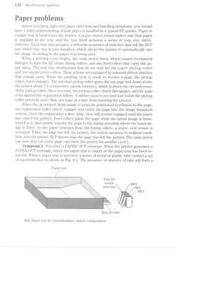
![Paper" ]J’}“‘Ob/,(3'?*"7"2,S H9
code that is tiniqrre to that particular paper size. Microsvvitclies are activated by the
presence or tabs. l/lain logic interprets this paper type code, and knows autoniati~
cally What kind of media (paper, envelopes, etc.) that it is Working vvith. Table 8-l
shovvs a typical paper code.
Table 8-1.
Typical tray switch configurations
Tray type SW1 SW2 SW3
Executive 1 1
A4 1 1
Legal O 0
Envelope O l
Letter 1 O
No tray O 0 O
1 : on (e1'1gz1gecli).
O : oll’ (clise1'1gagecl).
The presence of paper is detected by a inechanical sensing lever as shown in Fig.
When paper is available, lever rests on the paper. A metal or plastic shaft links
this lever to a thin plastic flag. While paper is available, this flag is clear of the paper-
out sensor. If the tray becomes empty, this lever falls tl1r"o1-1gl1 a slot in the tray, which
-‘‘.-'3‘ v1-5 I‘,-7"v§>"‘: v“7}i:,'>‘,‘:‘ ‘> '
¢=gwiritlli:m%$1§'m§753§
Papeiesensirag arm * ‘
% , Optoisolator
. .-. .-. 5;-.-=1-aw:=‘=<;;i
1 ;'Z'I'l'I'§ 'I~1:~*“;5i‘4"€i":<5‘
.‘.'.*.'.'-'-'.'. .'. 55:21 ‘res-i‘ w,~1»:/'
‘*1
{;:j:;:;:§:::;:;;£::;!,“F i~1;s.=fi.1':"~'.1;'I<<:;‘1.=.z=:
'4§;iEl:I;Z;ZE;:;I;._~;-'
"=¢
.~ » ¢ 0 » - ~ .
>l~I~I~I-Z-1'31‘!-1'..----nun .
' '~:-:~:-:-:-:-:-:-:
""==:=:?:=:=:1t5:=: =:?:¢"¢i$1$:nw
-:-:-:-:-::;:;;l' *1;:;:;:;.;._.;.;
E4-:#:»-:i:1:-:1:-:1:!:!:-:1:-:-35::-r
::.:;;-3;:-:-:;:;:;:;:;:;:;:;:;:;:;:;§!I!g:-1..L§_;_;éh2i:-_-_-_-_-3:-:~_-[~§._-:1,-|'
Ii-I-|'I-I-Z;Z;.;.;I;.;I;.§fI;s;.,.
*1 I
g it Paper avai..labl.e
Paper
P£1])(-3l‘—S€1lSll“1g arm _ tray
-;-3-;
-:-:-:-:-:-'
__ iiii- , _
“H. it tray empty
“R
8% Operation of a pape1‘~se1'1si.ng arm.](https://image.slidesharecdn.com/ozgdplurrtdj8c4ktjrb-signature-f36449d24fae8f28749ba408629a60e09bfd643da03035012a2b233e7710df3e-poli-180806114914/85/Easy-laser-printer-maintenance-and-repair-145-320.jpg)
![ran 11/L760/'Z.»CL-7"'Z/Z-C(LlS@]Sl§€'7’7'ZiS
rotates its flag into the paper-out sensor, which shows that paper is exhausted. The
paper-out sensor is usually mounted on an auxiliary PC board (known as the paper-
corz.r2"oZ. board).
Begin your check by removing the paper tray. Be sure that there is paper in
the tray, and that any ID (identification) tabs on the tray are intact--especially if
you have just recently dropped the tray. Re-insert the filled paper tray carefully
and completely. if the PAPER. OUT message continues, then there is either a
problem with your paper tray lD microswitches, paper sensing lever, or the paper-
out optoisolator.
You can check the paper ID microswitches by removing the paper tray and actu-
ating the paper sensing lever by hand (so the printer thinks that paper is available).
Refer to Table 8-l and actuate each switch in turn using an eraser of a pencil. Actu-
ate one switch at a time and observe the printer display. The PAPER OUT error
should go away whenever at least one microswitch is pressed. If the error remains
when a switch is pressed, that switch is probably defective. Unplug the printer and
use your multimeter to check continuity across the suspect switch as you actuate it.
Replace any defective switch or switch assembly. lnspect the paper-out lever and op-
toisolator next.
When paper is available, the paper-out lever should move its plastic flag clear of
the optoisolator. When paper is empty, the lever should place its flag into the op-
toisolator slot. Note: this logic might be reversed depending on the particular logic of
the printer. Actuate the paper-out l.ever by hand and see that it moves freely and
completely. This check confirms that the paper sensing arm works properly lf you
see the lever mechanism jairuned or bent, repair or replace the mechanism. lf the
problem persists, replace the paper-out optoisolator (or replace the paper handling
PC board). lf the problem still continues, replace the defective ECP.
Syniprern 2 You see ct R1lPER JAM message. The EP printer must detect and
report ])Etp€l'—j2.i.li1 condition. For most printers, a jrrirr occurs when any one of the
four followiiig situations do not take place. First, a sheet of paper must reach the fus-
ing assembly within some amount of time after the printing cycle starts (usually un-
der 3O seconds). Paper reaching the fusing assembly actu-ates the paper exit sensor.
Second, paper that reaches the fusing assembly, must clear the fusing assembly
within some amount of time (also about SO seconds, but it depends on the paper
size). The actuated paper sensor returns to its original state when paper passes.
Third, paper that is present in the fusing assembly must be present when fusing tern-
perature is above some minimum temperature (about 150°C). If any one of these
three conditions is false, a paper jam will be registered.
As shown in Fig. 8-4, the electrostatic paper transport system is much more so-
phisticated than those used in more conventional serial or line printers. As a result
of this additio.nal complexity, main-logic circuitry must detect whether or not paper
enters and exits the paper path as expected. For this discussion, assume that a jam
can occur in three general areas: the paper-feed area, the registration and transfer
area, and the fusing area.
Begin by checking paper in the paper tray. lf a jam condition is shown, but there
is no paper, it shows that your paper sensing lever is not functioning properly. lt
might be broken, bent, or jammed. When there is ample paper available, take a mo-](https://image.slidesharecdn.com/ozgdplurrtdj8c4ktjrb-signature-f36449d24fae8f28749ba408629a60e09bfd643da03035012a2b233e7710df3e-poli-180806114914/85/Easy-laser-printer-maintenance-and-repair-146-320.jpg)
![Paper" p/2“obler/'z.s M-i
L'J LD CO
mg? 2.7
fl _. E _-is .. .-_. x-
l* 1
1 1 P ‘ '4, I; ,___,,,.?,*_-1-; -._..;1- i
22 1,7,. _, -_m _ 5;&,_
l.?' C3‘!
.../ ii@/
8-ii A cross-sectional diagram showing the paper path. Hewlett-Pao1<ardCo.
ment to be sure that paper is the right size, texture, and weight for your printer. Un-
usual or special paper might not be picked up reliably. lf you are uncertain as to the
correct paper type, remove it and insert a quantity of good-quality xerographic pa-
per. This type of paper usually has the weight and texture characteristics ideal for
ES printing. lf the error continues, look at potential jam locations—-paper-feed area,
registration/transfer area, and exit area-—as described below.
Paper-feed area The paper-feed area consists of the paper tray (and paper),
pickup roller mechanical assembly, and electromechanical clutch as shown in Fig.
8-5. if paper is not reaching your registration rollers, the trouble is probably in
this area.
i/lechanical
_m_ / drive train
~.*E?EEE55EEE5E§E':-
............-..--~..L -'............. ~ L 3" '1‘ ‘
...---....~........--L .1...-...~“-".2211... -<11.“ uvoc .
....“ ...-nu...--..-.. .-<-nunu“-.-......»---.. ...----......~-...Iqlouoo ..---"...........-r _|...1-.......-“...”...-...-.-. H.-->-....---‘-ilbblbb ....-H-...-...-¢-| 4-.............................-~ -"nu-........
_| ~......::-.........:::|_ _.~.........-...-“...-u-..-_ L..."-.1."-1.-...I1.!
dr»---. r|a4rnnn|QIn0lltllh J‘-:1:>1“>-I-:1“:-pnnoiiozi‘ :iI;Z2I2..:..:.:::il
I§............ .--..-........1| in..............-..-...."-...... ..--.-........-
we " "
3 Q
::n:0:-:q||n4|: ‘onnzvlIn::::::::::0:|nqIv0vnIonn> ' lllI:b|llI ’
-alnuolcaooq |unnnnanuIl|p JQQIOQIIOOIIIIIIIIIGQIIDIOIIIIIIIUI Lu > ‘ .—
......-...... .............. ..-................................
........................--.-"... ..........-"..., -,--.............. Jh..“........................... ...........-... E.--......"-...
fiiq *1? ii
H..-..<--u--.-.::-"nuvilli; Z---~-1|-Z1112-3* 4 onc;;:=;;:::=:
................ ................ ..,.,..,_IQ'lUIIIIO{II¢lIIIlDOIIIlIlIl Qibililllillillll llinlllynhhltlill -ff||nvapY- 1
--..-~~.....-...“......--. QQQQOIIIOIIViliblllllilllilllblllll .1--....-.....r. Q _ _ _ _ , _ _ , _ _ _..-....“...----....-......, ....-...-....“N-......“-.-...... _.'|...-......-..-Hr-_ -. _. _. _. _. _. _.-_. _. _. _. .1 _.-.-----.-......"--....-...,. -..............................---- _...-..-............... ~ ._,_._._._.,._._.,..,.......................,. .-......".-“......--.-......... .......-...............-._ ,__._._. _._. _._._.
",,_...............,...,. _................................. .......................-"5 ,_. _. _. _. _. ,. _. _. _. ,
“Hl|0O00000ct(-.' '1--"....N.-»~-.....-~~---n ...."-.--...»nnn.-.... ' ' »' ~ >
__~u_“_. .... ... mm. ..
.,_ ,. I-._...-......-.-“......”-.,2 ...-"... -_.~_.'_.-_.-_.-_.~
..........-.....--.- ...».-.~ _. ._ _a_._._.,.
_“_.....<<_u... ......... E ~;,.-.¢-..,~=~;-».-Y, »~..~= i'}‘’n'A_--v'-Iit‘ . a _. _. _. _. _. _._._ ..m:m i ,.,. , _.
|:: : :::: :: "~----~-- -. ' .r ,- xv‘! _ . .. ~‘ ' -‘ ~' " ".-‘.-IIIIIIQI-5‘|QU'CIlWIiOIIllIy v‘,fi:y4H‘ ' ...". '-:.»,:.-;-_',;,.i;¢tm_'.;:"V-.->7, .,.' -' .' .' I . ,
"3 in. W4‘ r . . I -1 --1|nun-an."-unu»--u-. -~»~-nun-nu" H '*.~'~<> J
. ............... 1‘-1. ‘ .- .-‘.-'.-' -'.-'
,, 5-ijiii§§§§§555§§E§§§§§:E§§’ "”e;;@§;}:;i,&?§;E;.»:i9;At; 5
CL .-'- -—._ *4,::::::::::::::::::::* .::::::::::::::::::::::::::.
"~ .--" '. '¢.';::::::::::::" .::::::::::::::::::::::::::::::. . . . . . . . . .-." | “.... i-.n-‘ .......----....“»...-....r----- =':$ ‘;'"i“‘.‘-l'i_1_¥‘i: 1% '
_.- | 1-.,,-...,“ i,;-L-,=]-,-:1, .<...............................- -
I .:::2:1::::::t::::::::::::::::::t!!.‘.1-ii.-l‘+r~‘=’>T:
I1 ::::::::::::::::::::::::::::::::::::
;-;';~=:-c:';1.':~1,1;,:-::;=_=: .:::::::::::::::- -1+--1: :::: :::::::::. '=.c.i:-11‘-'==.~;,=_=.;.sz:'.
-' ', t:::1::::::::::{ "'§:::::::::::::::
via;-1‘rinM1iii=*"1r!!=%3>s;s~1a= .-‘ ""1"" 5"“:-1. 4-: “iiiiiiiiiiii -
.-" ' '§§§§:55:33::7:5-;‘:'f';-15:7"ii§§§§E§§' l;)lc1* 3
.135?»-'-?’tl:i;'i‘$§i;¥5€ii»us. _--" ' :::::::::::::::::::::::::::::::::::: , L
1* -‘ 1%’.-L':=t?ii.ii»lIh1li-F'i_ ::::::::::::::::::::::::::::::::::
'i=I=1I=1=1 =1: ii===1: =1:=1=1 ::::
' l'Oii(°.I'"-1.?i~‘i1:'~_1_=".r.§'E1‘J‘I.:*‘:i=;g@ .l‘Y5];1;:- -I-FF ".-'-155.‘,-" - _.=:;;“;-1.4. -~--:1: :1. . ... ....... ... ":§‘;:g%f::§|;i‘.11Q1i§U}w;jl
“ - ‘L. 5.‘ »-1; ;;55E;;5&5 ;;==*~-.".'-‘.1‘.'.%'. ,=~:‘.==r_.‘;1.-,»:'-‘_?‘-‘;§:‘-‘I',§ |_ “’l~,7,';-‘T,{].1Er,i‘,'§,1;li‘53E;3.,, , .. .... ,, at-"=1.‘.‘.“L<: :'.‘:».'.~"t‘.‘:1-.'_.~~
~3"’-*1-it’-N11-Ti=;§ii!:§i"‘ ' I. i ?1i“.';.‘r-l=‘:‘ "':;i,“;1-I‘1r;~“'a'_&:1.'-‘tzi (ti:-.1.i=11-,r>.,f;E*%=j~§~a's 1-‘;:l;=g'1jr¢g¢j:r,~:;1,ie$
‘...—- ' "~_ =‘.1:k-Li» '
"'— ’ ---_ "*-'.‘,i‘-"3!-.'.‘'§'“'I1;=;.._- '_--... "-.
=i§§;?§3"E§ _“ "
.'4'¢,¢ ='=;={-1-=1: =i-.1t:5r=wl?»1.-.:Y»'==~‘-in=<»:=11;1-1» . " -'-:-'-: ~'-.-:-:~:».-'-:-:':-:- :-:-:-:-:<-:-at-:~:-.-:-:-:-.-:~:-:-:-::-:----.~:-2:-1-2;:-:-:-2+§1Hi;§{.;§,1‘§5,y$§§;j*1,§1¢j‘i5‘J‘Fl‘.% ‘ 52-:-:-:!.:<:;:;x-1;:-:i!1?1$¢',§&;-_23:13:~>:-an-:;YI:<-:-v:4I>r§:;:§:;:;:,:-1;:-:;:45*‘-:;1-:;:;:§:g;:;:;:;:;:;>:;:;:-Q:-:g-2-:2%'§:;:;:;:;;:;_;:;:;:;-
. -'§' w-
. ~====§====g$?g=;$%=:=$B=-==:=r§;=?E§=!=a=_$‘4}¢=~==£$s¥=2¢gE====Ez€=¢=;s=:;:==i1=====as==éi=:=;=i¢;s;<===ss=2r=a;=x==::==;=:ss=:=::
S . . ' . ~ .<.'a-::>'»s,-=:==ir=e%=¥;1s:=a:&a:=::me=r§$!nx¥>?¥§=2*?=>s;.5as:=$s:a=:====n=a==:i=====¢===23====ie==e===:===;=::;@s==1-?:~.v1':-‘-:;-i QUsklan.irgggii_;.,3g;¢i;eii::a;r e -:'.~:~:»:-*-~:-:-:-:-:~.-"'-:-:r-:~.-:~ :.~‘-:-‘-:-:1'~.-"-..~:-.-:<<-;-:~:-.= . '- .—.-1"-2-.-:44-:~:~.-:~:-.-.-‘:~‘-11¢-:-:-:-:-:-.-:-:-:-.-:~:<-:':-:~:-:-:-:-
$1-‘ii-:r_,,;7:~.'=-1i<;< 8» ,:;:-:~:-:1?-:-:-:-*-:-'1'Z->=:»:->:1§-act-2>:~'-:3‘-:t~:-:c-1-:;:;x-2;:-:-:-:3-iakt "---.>:»:-:~'~:;:-:->235:-1-:1:-:-ti}:1zgg:;:;:;:;:¢:-:-zi-1-1-2».= =1-1 =v=~1= i -»=-nil -r ~ V is; 1‘-'.-.“=-1‘ 1 --6'2§'1'Qf;Z-141'i:5:Z»I'I7I-I'Jl'O'Z*2QI'I'f:I'Z7Z-'Z§§$'C'I;,;Z‘I*£$'I-fI'Z:§£-Q1-.-. .,1?|;|;4;:1'.-.~:-:~:-:-:-:-:-;:-:-:-.-y.-.;-.-(.-.-.-x<-:-:-:~:~.'=:=<'~w-,.;.=;ig§.».;..L-nu;g:;;ri:gg:.>‘ ;,;.;.(.§.._.-.;.;.;.-;.;.-.~.;.;.;,;.;.>~._.*,;.;.~.;.-._..-.;. .-._.;.;.;._./;.;.-.;.;.;._.-.;.;.,.-5 . __ -».' 1.3.1.;.;._.-.5.-.~._.;.;.'.;.;.;.;.;.;.;.-.;./;.;.;.;.
-5.1;-:_>:1=.=_ - ~ .<:-.,:-- -_-.-<-:-.-.-~~-a~>.-.-a»:-.-2-:;:-.-:-:;-.-.;.=-»-.~:;.-.,.-.->.‘.-.v-2+»-.»._. __ -.-.;.;.;.;:;.¢.;.;.;._
.1='-:.-we ‘7."‘-T‘TiE5.'ILf¢$*b§:¥:f -" '5,-.,,_1~ - ' - 1»:<~:-:-:-:-:-::-*+:-*' -:-:-:-:~:-:-:+:-:-:-.-. :-:-.21:-:-: .~:-:~:-:i: . .+;+,¢-:-:->:-:-:-:-:-:-:-:-:-.
(" ?§¢:1;1:-“.?:7.;;“-'»:¥!-f;Q-*<*.:.'Qi:;"“-'3<'?"'=:1§i:‘:=:15:3:I:¢§I:1:=:$:$:=:?$:§:§:§$$$:=$§:1:!:5§1:§1:I:3=:!:§1:=:?:i:I;¢$:i:I»:-.-.-:>§g¥;?"1'1$:?:?:1:1
:I'I:,l§i:I'I:?'1.¢:5E=§=E1§¢¥:=E¢'.-t>.-'».=5%$"""'3-E-31313¢E$§IEE§I:1Q@:-'1:1$:E1Fa-zii151411:$3:=:>:%=:l:='1:¢:I:I$:1:I$:i‘$=:¢:-:?:-:1:=§!$§':':"
:1?»:$i3:1§:?:§:1:I$?:=t1:1:='1:!§$:1?:>:1:I$; ":§?<'7:$:1:‘1$:!:3§3:§;5$>:5:§:1:=:;:2:1§>:?:’;:€:1:15:1:1:!i5:1:?:¢:5:¢I?:1$?1F:7:7:Y$:!:?:1:1:F:1:¢:!:1
:115:}:I21$:1:1:=:;'§;1:;$:§:§>?$§§:1§:31:§;_>$:I:5:1:§:1>:~:§.»:;.- :2<=z:§:5}:$35;1:1:-:I:tf:1:§:§:I:§:§:§:1:§:1:ES:§:§:=:1:7:i:§:3?:;§:§:§:§:§:"
:Z;-:~:?.=$:=:=:§-.-'2-zk-ac*5:-1E;1:-:1:;-:=:¢:¢:=:<=;§:5-3-5:-:7<F:-:-r.- . .~l;q,‘.'}o‘;:c-'-'~:1:-:-:-1%:I:5:1§;§:-:41:~:-;-$51:-;t~;»:“:1$:<-:1:-:4-1-:<-;
:»:5:1:3i§5!§i:-:?:1':1fi::§¢:i:i:‘-:!:~:1:if1:-13:3:if’-2311;:-z-ti:-:1$:3:§$!i:°§:1§1t?:-1;-:-.i: -*i:1:1:5:1:1:2-:-:5:¥:3:I$ a5:i§:5:5:1t,?:5!3:3:1:
.~:-:-:~ :-.>:;:~:-:;:,-_:-:;“ -'-:-'¢'_'-:-'g~:».-'415;:-:;:;':-:.-:-'-'=-:-:<;:5-.-:~:-q:-:-.- . ' '~:-:-=:-:-:-:-',:'-:-' :-:-:;.-:;:-:;.;:;:;:;:;:__ - _ - J""5"'1:iE:'-.§$:§:$1:-:;-:-:-;:-:-:-
¢ ~ I -.-:-'.-:;.».-.~ . .->' -:-:-:-:..-. .-:w.-. .-:-:-:-:- -:--:e O 1-:‘-M?‘-315533-5:5:-:1!-:-:;~:~.-'- :1» :-:¥:~:-'-'- :~:-:-'-:-:»=:<-:~:~:-:-"-55'-"-:-:-:2-:-zq:-:-:~:-:-:--:-'-11:--/.-V- -
,_:_~..~. . ,>¢..=:. ,. .-wk“ r q __ "-'-'-I-1:15-123555;"2:) ' "';;~.-:;.->:~:->q~_:-:;:-:k-$'-'-:-:-'-:-.-$:;:$:~:-:-£4-.-E36:-:-:»:$:-:15-.;§-2-:<-:-:-:~:-'-:-:-:v;¢<;.-$:-.-:-.;f-:~§:-:-¢ --
.;:;:;_;:g:;§;:_t;;;.;:;:»',;:_Z9_';:;:§>_§:5;,;. _-:-:>:-:5-2->:-.»:$:-33-:-:-1:~.-:<~:-:<g-:-:’¢:-:-:;;->.-:~>§;>:-.->2-_<5- :-2-1-:-:-:24-:~.~. ........ .. .............. .'.-.~.-.-. -.~.--.- .-,'-;.;'.-.;.;.-.;'..-.;.;.;.;<_. ;.;.;.;.;_.;.-.~-;.-._- ;.;.;.;.;.;.,:.;.;.;.;.;.;.;._._.1. : S . ..,2-E7:I:Z:1'!:-:'-I§¥i?:l:!:i5:1:I5$:i:$-159:1:>.'I:¢:I:k15:35:53:7:-:I-~$‘->-:1:-§¥:¥-1:->:-:-:-:Z?-:-:-:-:-:-:-1115!:-$:-2 :-:-:-:-:-:-:-:-:-:-:-:~:-:~:-:--
Paper tray
Paper
8-5 Simplified diagram of a paper pickup/feed mechanism.](https://image.slidesharecdn.com/ozgdplurrtdj8c4ktjrb-signature-f36449d24fae8f28749ba408629a60e09bfd643da03035012a2b233e7710df3e-poli-180806114914/85/Easy-laser-printer-maintenance-and-repair-147-320.jpg)
![lit-2 ./l/L76‘?C/‘Z/CL-‘l"Z.r*Z-CtftZ S1/S‘£6'}*7’Z-S
Inspect your paper tray carefully. Although the tray might seem foolproof, it ac-
tually plays an important role in paper feed. If the plastic tray housing is cracked or
damaged, replace it with a new tray and re-test the printer. Note the movable metal
plate in the tray bottom. This lift mechanism keeps paper positioned against the
pickup roller at all times. Remove the tray and paper. l/lake sure that this plate can
move freely replace your paper tray if it does not. Observe this lift plate as you in-
sert it into the printer. The printer should lift this plate up as the tra.y is inserted. If
this does not happen, repair or replace the printer lift mechanism assembly. Add
some fresh paper (50 sheets or so) and gently insert the paper tray. Be sure to insert
the tray fully and squarely. lf there is any obstruction (or the tray does not seat
squarely), find and remove the obstruction.
Next, make sure that your main motor is functioning. Keep in mind that the main
motor drives all rollers in the printer, as well as the photosensitive drum. If this motor
has failed, paper will not be drawn into the printer at all. You can observe the main
motor and its gear-train assembly by turning the printer on, opening an access cover,
defeating the associated interlock switch (if any), defeating EP cartridge sensitivity
switches, and initiating a printer self-test. lf the fusing roller temperature is above its
lower temperature limit, you should see motor operation immediately. lf the main mo-
tor fails to operate, replace the main motor driver circuit or EOP as required. if the
ilj18.l1'll"llO’tOl‘ continues to malfunction, replace the main motor assembly.
The main motor turns when a print signal is first generated in main logic. lt con-
tinues turning as long there is paper in the feed path. However, even though the
main motor supplies the force to operate every roller, pickup and registration rollers
are operated only briefly during each print cycle. An electromagnetic clutch (also
shown in Fig. 8-6) is used to switch the pickup roller on and off at desired times.
i/lain logic generates a clutch control signal that is amplified by driver circuits be-
fore being fed to the electromagnet. When deactivated, the plunger disengages the
.-.1-v-rn-...
. . l/lechan.ic.al
Pl10l1OS€11S1l;1V€ - (’4- -LI F -
drive train225222:sssz=v“4=z=2==:===2=i _ [......:::..
:::::::::::... ..::::::::::: __1-m-1»_Q 1 U111_ _ 1.....“.--“....-............| ‘.1...--...“...-.....r.r
5::::;::::::::::::::::::::::? _.--..:::::::::::::::::::::::.:._
-;::::1::::::::::::::::::::9.11:::::::::::1:::::::::::::::::::'»yr.nu-1|N-.N-nu.-'?a-...-........|----.~~-"----H.»-..|-L
'.,.................‘_._....--..--<in--....-........~.».l....2.n_
.. "~.'.:'""'_'.l-P ».:::::::::::::::: :::Z::§::I1I::::.xM,W_g§:n5;re;;’g,,,;;:_ -IJAQL .5.-<..-....--"... ................r.|
en--‘~ , ' :................... ..................J
-. .».-:-:15:5:5:1:1:?:1:?:=:=:=:1:1:1:=:1:?:1:7:-1+:-:-.-. . M»: ' ' ' " ' ' ' ' ' ' *' ' ' ' ' ' ' " ' ‘ " ' ' ' '“...-.._._,,._._.,._._<,._-_-,-,_._.,-_¢..,._-._... .~ ~-'"-~-"-~~- "'""~"~-~~
. 1 . :: ::: 2 ::: 2: :: : ::: : : ::: :1: :::.|1-1-;~:1;-1:-:-;-_<1-1-;.;.1-;-;.;.;.5;.3-;-;.;11-;.;.;-;:g.;.;.;.;.g:;5: . . . . .- . - . . . . . . . . . . . . . . . . . . . . . .
-.-.-.-.-.-2-l-2~!<~2-I-1-I-1-I-I-2'5I-2'1-bi-2-I'€-1'1-Z-3'2-It-2~2<'i~I~2-E3-I-24-2-. - -- - ~- - - -3 -5 - -3 ""‘ - - ~ J - ~ - ~ ~ ~ - - 3 -1.3.14.5.1.3.5.ya.;w,-.~-1.‘.-r.-.~-'.-.-.-.5.3.‘-7'--w,-.~.-.~v.-.-.-.-.g.<.~.~.'.w-.-. . . . . . - ~ . . . ~ . . - . 3 E . . . . . . . . . . . . . . .
.<.-w.-.~.-.-.->1-.-1':-:-.-2:i:-:-:-:-1-::~.-.<:-:-:-:-:-:>:-:-:~:-:-:-:-:-.-:-:-:~:-:»:-:-'- ; :: : : : : : : '. : : : : : ; ; : 1 : ; ; ; ; 1 : : : : :
,_,,__:§:§t§:§:§1§:i:§:§:§:i:§:E:5:5:§:§:}:!:§:§:}:!:§:!:I:i:3:i125:5:I155:l:I§$:1:!:i:l:1:1:4:!:1§i_... . ::::::::::::::: 77 ::::::::::t:t::
~','.’.'.',",',‘.','.*,',*.'.=,*,~,~,<,-,~,-,¢, :I:1[-Iu}:~:{;:1:~:~}:-j~]v:-I-Zn:-I-5211-:-I o o v - 0 r 1 o 1 r - o o v - - I - ~ 1 0 u 1 ¢ I > - | - 4
-:-:-:-:-:-:-:-:-:-:-:~:»:~:~:-:-:-was-. . .. ....u:-'-:-'~:~:~:-:-:-'~:+:»:~:-:-:-'~:-:~:-:-:5-;.;.;<;.;.;.;.;.§;-;.;.;-;.;.;g|a+....11.1..3.“....-Q-.§;.;.;.;.;.5!;.;.;.g.;a.~.;I;.;.;.-.3. Liiiiiillilllli I21“:-.IIZIi5'1
...'.*.‘.'~'.~.'.'J.'.~_-.*.=.' ~ ‘|'IIl"llIllI1O'IOv o -,0~,'_-_-_v,|_-f-§,-_‘_~,>1--v| l-U nu"---.-nu. v-nan-<|~4“
.-.-.~~.-.-:.-.-,~,»,-_-,~_-,<_-_- .-...............-,-u~~|- ~;-_._-,-_._“-_~,-,v ~_>_-1-;-'-; 1;‘? nun...-~-.. ----»---....“_._-_._-;»_._._-_..._._._._.,._,.,. ..~~~~.-..--"N-.........-. .'.‘.,.,.'._.'._._._.;.,._._-_.;._._ F.“-»-..---n ..............'
_.1.1.;.;.1.;¢.;.;.-.-.;.;.-.-,;)-.- --....:::.:::::,..,..,:....--: -.-,_-,~,-,;-,~_-,~,-,-.-_-_~_-,1, .A: ,...........,i ---»~n.....|
2IZ22221...}.....12iZ1I:.21IZIi-12 "I~I'1~¢I-Z-5'2-1~I~C-3-1'1-W P222122"‘“'.....................ZZ!1iIi2fIZZ‘
E§§1§§;§§j§§§§§§;};;§§}:§:j .;:::::::::::::=:::::::::::::::::::§:; 1:3:5:§$:§;§:§:§:§:§:3§:§:§:§:_ '1_::::: ::::::::::::::::::::::::::::::::_r' ...,
:§:}:§:§:§:{:{:§:§:{:}315,4::::::::::::::::::::::::::::::::::::::::#12:1:1:T:E?:1:?:i:!:1:T:Y:! '~-:: ::::::::::::::::::::::::;::::7rL..i.....n . .____;_:_;_:_,_,_,_,_,_,_,_:,,::::,m::;::....... .. .:,¢:,m:::: ._:_:;:;._:;:;.;:;:;:;,_}>
.1:1:f:=:!$:!:f:=:=:Y:1i:1:'Ifiilirirrirrrr ::::::::::::: ';='!~!:==I-I-I-1~:-2-:-: -_-;:::::::::::::::::::::::;;..::::::::::::::::::::!-. . .,_,_ .i........... .;.;..,.;.;.;¢.;.;.;. .._,.....-....-..-v-".._. »......................a 1LJ_“n'
.34.;.g.-r-.;.~.-.~.'.-.-.~ -------¢-~----U ,- -| ~--.-...-“... ._._>)._-_._>_._._-_.,. ..-".............|,.. 1........-...“-......-..a ii;-‘, _.~_. _. _. _. K
-.;.;.;.;:;:;.;:;:;:;:;:;:;:z::::::::::::::: ;;:::::::::::: ;;-:;>_:;:;z;;;;-;-:;: -~-an---— K‘-~~--' - - - - -
:::::::::....: L A ::::::::::.... .-.-.-.-¢.-:-'.-:-.<-:_ w .-P
is?aieisEziaizizisiaiziaiaiz 5; ii 3-"I3-:I3-:21-:13-:I3~‘E:§:§:§:§:§:§:§:§:§$§;§._§§§{§§§§§§§§§;: ;;§;§§§;::::: ;::;:;:;:;:§:;:§:';:§:§: :::::: -j.-'1.-‘j.-‘j.-"j.-'j_ _ _::::::
' '“"""""""""':3:-:21!11iii!IIii!1}I212CIIZZII2212K211222222I‘gt-I-1-I-1->1-I-t~I>:'Z-l-2-£534’ 5----~ *1" -“ -' -' -' -‘ " - - - - -"- -
*1 15‘ E=E1E=E1E1E1E:E1E=E=E..
.. - *1
W1 <1-l3 blutch.;.;.;»:.;.;.;.1-1-3.3.5;.3.3.;.;.;.gag.1.3:.-.-.-.-;~2>2-1-15%-L-L-2'Z‘£-I-2-1~.-I':-;~1-:- " “* '"'"
§
L
""~"-:-:-:-:-:+:-:-:-:-1-:-:-it-:-:-:1:1:?:?:1:1:!:=:!:<21:1:1:1:!:!‘¥:i:1:1:1:t1:1- "imi IP53?
51312151E1515155121S=kE=E=E=E1S1E=E=E:E:5:252E:2:5:E:?:E=E=E1E=£ri$5:2:==' 5 E555552235 :5:5
'1'i:1:1:I:2I:~:1:i:¢:?:IS:I:I:¢:I;1:1:1:I:I:i:1:I:¥:i;=;l:f:I;I:=:1+ =¢:1:‘-Fr" ::::21: :::: ::::
*.=:i:?'5:1:1$:5;§1:!;i:I§_5;!:3;<;1'l‘"" ‘ : : 2 1 2 2 2 1 2 2
""3'3'3'3'5'1'5'1'T'5"' ".-..-.饑‘~"‘:"‘ =‘l1:‘li-‘ I‘; ' " r .-.v.‘=L*':.=i 1'???-if
. i *~ws.¢@aF.er==i=‘
"“““““*—_“ "1W -- ---'=‘~'~ ‘=*.-‘.‘.1'5.i-‘;~'. I S ; ,-:i.Trj»'. .*I»r‘1:w§:5-1*‘-1;‘.'T‘.-““>1.>i.--.
" E »iilwtfrlwailrit-11-jwifiérsi-r1tr
-; r
' (3 1i I r ~ '<."‘§“.‘>.‘€-;7l1"“L'C'*'§“‘-‘f-‘Z _» .» 1 J LQ.-.».:-.-¢.<.-'=.~,-:-.-.-.',‘; .»: »;:-<=<~.=,,;..»;,;- , , , ‘ _ ,, l,.._.;',r~.'..~_.- .,,»_»-.-.;._~ ~_-.-.,~.,-.~.;=i~~;;,;,._,.,
; 1 (1115 Q1
I 1 ' ' ' Eli-.‘=iii‘dz?lltN?Ell$il~‘§?‘= .
....‘, _ , x , . . J l
,1 _ Transfer
l i ansfei Corona
rofler
at Simplified diagrain of a registration/transfer area.](https://image.slidesharecdn.com/ozgdplurrtdj8c4ktjrb-signature-f36449d24fae8f28749ba408629a60e09bfd643da03035012a2b233e7710df3e-poli-180806114914/85/Easy-laser-printer-maintenance-and-repair-148-320.jpg)
![.PCt"_].’)€’2*"" 3;)-roole/ms‘ M3
pickup roller from the drive train. When activated, the plunger engages the pi.cl.<up
roller, which causes the pickup roller asseinbl.y to tiiiin and grab the next avail ~ le piece
of paper. A separation pad beneath the pickup roller prevents more than one st - tfrom
being taken at any one time. Paper stops when it reaches the idle registifation rollers.
Notice how paper vidll bOV this is a normal and harmless function iii. the paper path.
lf the main motor operates, but the pickup rol.ler does not turn (you can see this
during an open-cover test print), inspect the pickup roller clutch solenoid. Note
there are probably two major solenoids~—one for the pi.cln.ip roller, and one for the
registration rollers. When printing starts, one of the two solenoids (the pickup sole-
noid) should engage immediately. lf no solenoid engages, there is an el.ectronic prob-
lem. lf the pickup solenoid engages, but your pickup roller does not turn. (or does not
turn properly), repair or replace the pickup mechanical. assembly. There niiight be a
faulty clutch or other mechanical defect.
When the pickup solenoid fails to actuate, use your mul.tii.neter to measure volt-
age across the solenoid. You should see voltage toggle on and off as the solenoid is
switched. If voltage changes, but the solenoid does not function, replace the sole-
noid. lf voltage remains at zero (or does not switch from some other voltage), there
is probably a fault in the solenoid driver circuit. Troubleshoot the solenoid signal
back into main logic. You also might simply replace the pickup clutch PG board. lf the
problem persists, replace the ECP.
Finally, you can check for feed roller wear by measuring the distance beiliween
the trailing edge of the paper and the end of the paper tray just as the sheet stops.
This time occurs between the point where the pickup roller stops, and the registra-
tion rollers start. llorinal.ly, this trailing edge should advance about 3 inches or niore.
lf it does not advance this far, your _pickup roller is probably worn out. Replace the
pickup roller assembly and separation pad.
Registration/trarisier area l§%egisti'ation. rollers hold on to lzhe page uiitil its lead-
ing edge is aligned with the druni image. Force is supplied by the niaiiri inotor, but an-
other electromagnetic clutch switches the registration rollers on and oil’ at the
appropriate time. Once paper and the drui.n inrage properly aligned, main logic
sends a clutcli control signal that is amplified by driver circuits to operate the registra-
tion clutch solenoid. Aftei;' the clutch is engaged, registration rollers will carry the page
forward to receive the developed toner image. The i’€glSlli"ELl]iOl'l/lll'&llSf€?i' assembly usu-
ally consists of registration rollers, the <;l1“ive train, a ifegistration clutch SOl€f[l.Ol.Cl, a
transfer guide, and the transfer corona assembly as shown in Fig. 8-6. if paper enters
the printer but does not reach the fusing rollers, your fault is _probably in this area.
You can see registration roller operation by opening a housing, clefeating any
corresponding interlocks, and defeating any cartridge sen.sitivity switches, then
initiating a self-test. ilse extreme eaution to prevent injury i?i“@B."it higi"i~--"veitage
or optieai radiation froin the Writing rnechanisin---espeeiaiiy tiroin lasers.
Watch the paper path and drive train very carefully. If you see an obstruction in the
paper path or in the drive train, unplug the printer and allow 10 l1'lll1li'l1<53S for the fus-
ing assembly to cool before attempting to clear the obstruction! Replace any gears or
bushings that appear damaged or worn. Pay close attention to any tension equalizing
springs (called ZO’?'”'S'?;-O72, springs) attached to the registration rollers. Reseat or re-
place any torsion springs that might be damaged or out of position.
>-—-»C-Jr—}QC?“(D](https://image.slidesharecdn.com/ozgdplurrtdj8c4ktjrb-signature-f36449d24fae8f28749ba408629a60e09bfd643da03035012a2b233e7710df3e-poli-180806114914/85/Easy-laser-printer-maintenance-and-repair-149-320.jpg)
![|=---i eea Mec/r2.o:2r2/Zcal s;z)ste/mis
Carefully inspect the n.ionoi‘ilament line encircling the transfer corona. l/lake
sure that the line is intact, and not inter*fering with your paper path. Do not approach
the corona with your hands or any metal tool! if you see signs of physical interfer-
ence, unplug the printer and allow high-voltage to discharge before replacing the
inonofilament line or transfer corona assembly.
lf your main motor and drive train operate, but registration rollers do not turn
(or turn properly), inspect the registration solenoid clutch. it will usually be adja-
cent to the pickup solenoid clutch. The solenoid should engage moments after the
pickup roller disengages. if the registration solenoid does not engage, there is an
electrical problem. if the solenoid does engage, but registration rollers do not turn,
your mechanical clutch or registration rollers are probably worn out. Replace the
mechanical registration assembly.
When your registration solenoid fails to actuate, measure the signal driving the
solenoid. You should see the signal toggle on and off with the solenoid. lf the signal
changes, but the solenoid does not fire, replace the jammed or defective solenoid. lf
voltage does not change, there is probably a fault in the solenoid driver circuit or
main logic. Troubleshoot the solenoid signal back into your main logic. You might re-
place the registration clutch PG board. lif the problem persists, replace the ECP.
lirrit area At the exit area, a page has been completely developed with a toner
powder image. The page must now be compressed between a set of fusing rollers~—
one provides heat, and the other applies pressure. Heat melts the toner powder, and
roller pressure forces molten toner permanently into the paper fibers to fix the im-
age. As a fiiziecl page leaves the rollers, it might stick to the fusion roller. A set of
evenly spaced separation pawls pry away the finished page, which is delivered to the
output tray. This step completes the paper feed process as shown in Fig. 8-7. Main
motor .fo1.*ce is delivered to the fusion rollers by a geared drive train. There are no
clutches involved in exit area operations, so the drive train moves throughout the
entire ];)1"il1'l1lIl,§, cycle.
it is important that the printer detect when paper enters and leaves the exit
area. Based. on paper size and fusion roller speed, page has only a set amount of
... i.i,.-,=,=¢,v.@;.i,. A ,,__;,,._,,
. . . ;<.-rel>w‘<’-vi .-:1"?I‘1'1'I'¥'>Z'I-I-I'I'H'I'Z'r "*3 ‘I'¥i'm
- - ._ Q F 1 i
'“= sense a+flm@“W
pawls T *‘ * i
H T , . wt P1i@i@S@nS@1‘l. 2.-ip<;‘1.' / '~‘, E
I. '~Z-1-H-.~Ii-1'2~2-S-I-2-I-I-1+1-1+!-1-1’
I -i_ -:-:':-:-:;:-:-:;§;:;:;:-:;:;:-:-:-:-:':-:
.¢=e.';}!;.‘-1?t$f4='=ii;:mm. ‘ ' - -i‘:!l:,~'[;I|_m‘rN'-‘,' ,-I:v"~ll-Clll‘--Eu-?-l-‘-lflfidvin. '- i =-ii-i--'-la. _i.~..-,."Il;1)E?.‘-<fi'?11‘fiflffi?"?11:"¥%i'§iE3¥§-1,‘ ~ ~'u=‘-~:-,3‘,-1:-:._:;:;=,r.'..'<'~:.;,i},'ifjfiiw<1¢fn-1'-Wq5,iE§(i“-2 —,.&,.=.~¢,.,-,..,...~.. ._.=.>~...-i M >1v' . ..,.,».» ,
i
i%$§fi§%§fi%%
In . , .-,.. 11 . tarresrssseeass aha“ — — "1-7‘=1"-'.=I'i"2?.' 1II:IIlII"""'J':l::::::: ¥'l‘5"5L‘l":‘.'*ll§~:
it ‘T “Sim L’ r‘ O in Q‘ Paper-flag‘::::::::::::':::"::":".:::::::::::::::::::::::‘:-.
hmmmmmnmrmmmnmemma 1 ~
12252222222222.2:522:22:2:zszzzzzzszzzzzszsszzi. @V(Z1
"nmnnmawmmmmwwwwwm-.,‘|‘,“‘<“i‘:"i,‘v",;i,!QUJ!Q'fffi;QI§QZm'];ff‘ . . . .. .. .. .. ::: :::::::::::::::: ::.
‘wnmwwmmmmflywmmmaaezmu" ‘h!lIl-hUII1III- ---<11-01-in-0-0 ~l¢¢¢|-new--ensl-
.-‘-nu-~.n-~->-n¢-u--¢|-...... J-.--..-u-1---..¢L
MmmmwmmmmmrmmmmmgI-
‘ ' ' ‘F1“5“=11"=5"===‘EE§E5EEEEE§Ej:35EEEESEEEZEEEZEEEEEEEET
D1-We tlm-1-1
“*5---****i**§**ii“”"
8-7 Simplified diagram of the fusing/exit area.](https://image.slidesharecdn.com/ozgdplurrtdj8c4ktjrb-signature-f36449d24fae8f28749ba408629a60e09bfd643da03035012a2b233e7710df3e-poli-180806114914/85/Easy-laser-printer-maintenance-and-repair-150-320.jpg)
![Paper p~i*'obLe'ms M5
time to enter and leave the exit ar'eabe1for'e a PAPER JAM is initiated. To detect the
flow of paper, an optoisolator is usually actuated by a Weighted plastic lever. An ex-
ample lever assembly is shown in Fig. 8-'7.
ilormal.ly, a paper-flag lever protrudes down through a slot in the empty paper
path, Which leaves the optoisolatoi' clear". its ifesulting logic output indicates no pa-
per. When paper reaches the lever, it is pushed up to the paper level. This action, in
turn, moves the flag into the optoisolator slot, causing logic change that shows pa-
per is present-a timer is started in main logic. When everything vvorks properly, pa-
per moves through the fusion roller assembly. As paper passes, the lever falls again,
returning the optoisolator to its original logic state. if the optoisolator returns to its
initial value before the timer expires, it means that paper has moved through the exit
area properly. if paper remains, a PAPER JAM is indicated.
A long-term timer vvas started at the beginning of the printing cycle. if this long-
term timer expires before paper reaches the paper flag lever, a PAPER. JAl/I also is
generated. As you might suspect, there are a variety of problems that can cause a
jam error.
Begin by checking the paper path for any obstructions. Unplug the printer and
vvait l0 minutes for the assembly to cool before exposing the fusing assembly. lt might
be necessary to remove secondary safety guards covering the heater roller. Remove
any obstructions or debris that you find to be interfering With the paper. l/lake sure
that your plastic separation pavvls are correctly attached. Clean the pavvls if they ap-
pear dirty. inspect the paper flag lever carefully to be sure that it moves freely. Replace
the flag lever assembly if it appears damaged or Worn-out. Also check all intercon-
necting cables and Wiring to see that the paper lever optoisolator is attached.
The drive gears that run your fusion rollers are often attached to a door housing.
ln tlus .vay, fusing rollers are disengaged Whenever that access door is opened. This set
of gears is sometimes called the CZG/,"'Z:7...?(2’}’t"LZj C()?.il.§l3[-'2'/HQ assembly. if these gears are not en-
gaging properly because of vveai' or damage, the fusion rollers will not operate (or op-
erate only intei‘n.u'ttently). Repair or replace any faulty delivery coupling components.
if the l1'l€Ch.£11li.CS of your exit area appear to be operating correctly, you should
examine the oper‘a.tion of the paper flag optoisolator. Replace any safety guards for
the fusing assembly. Turn. on the printer and use your multimeter to measure voltage
across the optoisolator output. Note that you might have to defeat any open cover in-
terlocks to ensure proper voltage in the printer. Use extreme eautien when mea-
suring, and stay vveii eiear er‘ the high-vuitage eerenas. l/love the paper lever
to actuate the optoiisolator. You should see the output voltage toggle on and off as the
optoisolator is actuated. if output voltage does not change, replace the faulty op-
toisolator. lif voltage changes expected, but paper jams are still indicated, trou-
bleshoot your sensor signal back into the main logic circuit. if the problem persists,
replace the E-GP.
Syinpturri Si The jJ'7"”Zi~"lZ/Z1636], "inzictge appears ‘amt/'2. ct smuciged bcmcl and over-
prim (Fig. 8-8). This type of symptom is usually the result of a Worn or damaged pa-
per-pickup assembly. A vvorn pickup assembly can allow the pickup roller to rotate
past its idle position such that it is pressing slightly on the page. lf this happens While
the registration rollers try to transfer the page into the printer, friction can delay pa-
per movement for a moment. This delay results in a dark band that appears rather like](https://image.slidesharecdn.com/ozgdplurrtdj8c4ktjrb-signature-f36449d24fae8f28749ba408629a60e09bfd643da03035012a2b233e7710df3e-poli-180806114914/85/Easy-laser-printer-maintenance-and-repair-151-320.jpg)
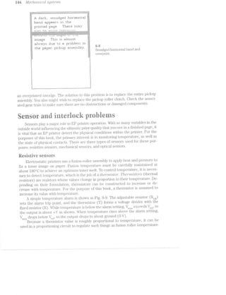
![iS’e'i*2.so/i*' Ct"i’2,d ‘NZ-l§€?"lOG/ii _p’2r*oble/ms iii-7
.ermisto1;*
.-.-.'.;. :4:;!£4: -;.;.;,;.;.;.;.;.;.;.;<;.;.;‘;.;-;.;.;.;.;.;.;.;.;.;.;.;.;.;.;.;.;,;.;.;.;-;.;.;.;.;.;.;.;.;<;.;.
:.-.~.-1-’-'-u'.'A'0-n'4.'.'-v.x'.*.'.'..'.‘.'.~.'-'.',*.'.ax".'.'.'.'.‘.-.-.*:.'.'-Y.-.1.
"I
r....._» p-....-.1 ,_.J
'-" ::— "'1! ,
-'-" : I;
I "-__ I 5;
I l
' +V Operational
V amplifier
§ fgh Q 3933 :§ag_ I
§:§:§ . .'_‘......_'}':;_.__w ,»= __ ,__,,.._,..:-_,_.__- :.:.:.:.:.:'I-_--7 _ b
$5PifiiiiiliiiiililifE151E1i¢E1§1E=E1i=E151f=i¢E151EIEliliiilifiiiiiiiiiiiiii H £3‘ I D ' ‘P “_._? t
" sens ' “ -‘v. al
T ' .................... .. ®~§r@§.--------u
V _ o ' f / voltage My
. "‘!"e1np l H @ tgmp.L i. Ht. "vmwwj
ln mt - Output]..' -+_ Y/ :|“| I?! 15.:
‘E i
ti»-9 Schematic of a simple temperature-alarm circuit.
A proporti.oning circuit is shown in Fig. ti-10. As temperature increases, the oscilla-
tor will produce shorter pulses, and vice versa. The output can be detected by ami-
croprocessor or .ASlfG, or used to drive a heater control circuit directly.
Thei;‘i.ui.sl;oi.‘
:5:1$:I:1:1:1i1§¥:1:=:I:I:1:15:1:1:111:?:1:1:iii:?:1515575135151}!E312111:15:!;1:=§i§IE=§1Z=i§§§§§ ii.
|‘1 '| - ‘if 1': |'u |'x__.___. . ..<-.-7.“. ,*_._ 1 ', ,' ',-‘ |' ‘, ‘ ', J ', ,' " ‘--............._..__
;_:_; .- .- |_||__.-uni kn! z": 1| .1 I"!
.;-j. ‘F 1 | 1 1 |
in (R1) .24 an (122) i,r' 12- Es‘ 15:}:
35;! 1 __~‘ 1 151$
:-1-: I "-. I ‘ " -.§;. --._ .55.
!, ~=::j_ ,i Proportionedat ~_.~ ‘n
"-L l output
l .1 T ”°‘1.f ill . I 1gt)DJ_/
-I~I:~'-:-:-:~:-:-:-:-:~:-:-1-:-:-:-:-:-:-:-:-;»:-:~:';~:~:i:-:~:-:~:-'-: ‘ - i =
1 ‘ "5
1
q i l<.Q (iii) A- T. |
-. -. 1. ~__ »__ :-
| 1 e -__ -.._l “J: ali ‘in I‘, ‘I: 1" .__:___ ._ .__=_-_|
*,*""i“"""' 1 n a | :' .- ~.-I " _- ~..-, 1': I‘! |‘| ’_ ___
j ciyiois
.............W 151 .- -
D1 100 E}u.-I5? (Cl)
Inna:
Scjhematic of a siimple tern Jerature-'aroiiortionin " circuit.. l l L.
F-===ipa-2lzeaée ii?:9-*3 C?) ti‘? Wit/ieeiia . i. isurs
When position or presence must be detected, a simple mechanical switch can
be used. set of mechanical contacts might be normally open or closed, then ac-
tuated by the presence of paper, the paper tray, closed housings, etc. The condi-
tion of each switch (whether used individually or in sets) is often detected and
acted upon direct.ly by a. logic circuit. The switches used in a printers control](https://image.slidesharecdn.com/ozgdplurrtdj8c4ktjrb-signature-f36449d24fae8f28749ba408629a60e09bfd643da03035012a2b233e7710df3e-poli-180806114914/85/Easy-laser-printer-maintenance-and-repair-153-320.jpg)
![T’i"’(J't_i'.¢l1")Z88/ZlE£C>OZ?’t’l‘2,Q Ct"i’2;(fZ- ’Z1'i"Ei¢ZIe?’l"ZOC/{IS Iili-9
ber that niost sensors are mounted on snrall PC board aissei'n.l>lies 'l1ll2Etl.-11“l“i_l.§,lll] contain
other sensors or elect.ifonics. ll?‘ you do not have the scl"iernati.cs or ~ t i.nst.runieiits to
checlr a sensor diisci;is;sed belovv, it is acceptable sin.ip.ly to replace that sensor PC
board outiright. if you do check. the sensoi;' and it Clli-3Cil{S properly (anti; its condition-
ing ciifcuit appea.rs to be *function.a.l), there is lilrely pii'obleni with the Iiillillf’.
§>'ifii'liL§li’ttliii?; i l’fO'Z..-ti ct .PzlPER OUT’ '.l’l"Z-i’3SS(.L§]€? 81.167’? 2. K/Z,C)'Z..l»_(];Z’Z» pCTt:]3e.?"i" is cz.rzi<;r2lZ-
able. Also, the errirroir‘ *2rml_glz.iZt virziot ctp;oeritr "EU/'2.-(-T?"l'2.» ]JC't]3€'l" is e;tr.‘/sz..cmsteal. if your paper
sensor is a niechanicafi svvitch, place your inultiin.eter across leads and try actuat-
ing it by hand. You should see the voltage reading sliift ibeetWeei'i a logic l. and logic O
C"‘§‘(3 U3
Jl.
ou trigger the switch. ll’ you ineasure some voltage across the SViTll1Cl.l but it does
not respond (or responds only interinittently} vvhen actuated, replace the defective
switcli. lf it responds expected, checl: its contact vvith paper to be sure tliat it is
actuated >vlien. paper is present. You niight have to adjust the switch position or
thread paper through again to achieve better contact.
Check. an optical paper sensor by pl_acing your inultiineter acr “ he photosensi-
tive output; then, try to a.c.tuate the sensor by hand.. You nught neec place a piece
oi’ paper or cardboard in the gap between t.i'a.ns‘nritter and receiver. You should see the
phototransistor output. sliiit lietvveeii logic l and logic O as you trigger the optoisoia.-
tor. ll" it does not respond, check for the presence of dust or cebiis that might block
the light path. lit’ excitation. voltage is present, but the phototran.sistor does riot re-
SpOlfl.Cl, it is probably defective. l%ieplace the optoisolator or sensor PC board assembly.
When sensor responds corr ly, the trouble is probafbily in your ECP. ll’ you do not
.l"i&'i.-"G. scheiinatics or test insti*uinents to ti.'oubl.eshoot in detail, SIi.i“i'l§3l§,?* replace tlie ESP.
hyrnpteiii F’Z..£.iS'2l-'l"2.»__(] Z3€*'l“‘i"2.5]38’}“‘(TLZ§’Z£/7%? co'2'z.Z1'2r"oli ils 'zIr'2-'z.ie;1‘]ectitre. .r[<?’;'~"i'tjJ€’r"CLt'2.t'7"e? 'i2rz.e'z.>e'2"
<;¢Z.r2l'mbs, or Cflt-"i‘7"Z/Z28 out of cfoiztrol. T87’/"'2.-]362"'l"‘(ftZi'2,(.-‘Fe?"_fZ2.tC3lT’Z..tCtlI’Z:-C)7"2,S rirffecrt q'z.tcr.Z/iZ1g/ or
“ZEN/Z1tit(lit/l/Z;>5(TtIf’ZOr'%‘Z,jIC>‘7" EP p-rirrnrz.-tsrs. Ui1.ipl.ug the printer and allow least i0 niinutes for
the printer‘ to cool and discharge. Discoiinect the tlierinistor at its connector; Use your
i1Tl.l§tllT.lll1“i€'t€i‘ to measure its r'esista.n.ce. A shoift or open Clii.‘Ci.ll.l1 r*eading niight indicate a
faulty thernii.stor*, so replace any suspect part. if you get some resistance reading,
vvarin the thernustor with your“ l’i.;i.igers and see that the readii"ig changes (even. a little
bit). readi.iig that does not cliiange at all suggests a faulty therrnistor. Never touch a
hot therniistor With. your il?'ingei*sl You inight have to reijilace the th.ei:'inis'toi" PC board.
if the lIll€l“jl.l'ilSl§Ol§‘ is intact, the problern is likely in the GP.Recoiinect the ther-
niistor, restore printer prniver, and use your‘ oscilloscope to check the outpt.rt of the
theriiii.sl.:or cond;itioning circuit; on the lilGP. ll" you do not have scliie.rnat.i.cs or test in-
struments to checlr the ESP in detail, ireplace the EC?‘ outright.
s3yi"np"teiii $2 llr'b2.z.. see ct PRINTER OPEN /rr2..es*su._ge. Printei‘s can be opened to
perforni routine cleaning and El?’ cartridge repl.acenien;t. T.h.e cover(s) that can be
opened to cessyour ]3l1‘llll]£Zl' are usu.a.ll.y interlocked with the Wrfi.tii.iig inechanisrii
and high-voltage poiver supply to prevent possible injury fll"<3l.'i§'l. laser light, hisiiig
heat, or high-voltages Wll.l.l€ the printer is opened. i/~i typica.l. in.terlocl< assenibly is
sliovvn in Fig. 8-12. The top cover (or soine other cover a bly) uses a siinple
pushrod to actuate an electrical switch When the top cover is opened, the interloclr
si>vit.cli opens, and the printer driver voltage (+2»4l» Vdc is slioiivn) i cut oii ;ii'rorn all
other circuits. ln some printers, l.'l.l§,l'l-VC)l.l}8g€ is cut off directly, whic ;ii'iliecti."vely dis-
ables printer operation. When the top cover is closed again, tl erlocl: switcli is
reactivated, and printer operation restored.
Q3U3 r<
C C/3
P-,+___ clC‘k
("Q (“U 1-?"
co on FD v--4 3
!___.FD W1>—- £r:‘Jl"'GO
r""' (D](https://image.slidesharecdn.com/ozgdplurrtdj8c4ktjrb-signature-f36449d24fae8f28749ba408629a60e09bfd643da03035012a2b233e7710df3e-poli-180806114914/85/Easy-laser-printer-maintenance-and-repair-155-320.jpg)
![EP ccn"ti"’id,ge ]_7’}"Of)[677LS l5 l
Syinptoni i You see ct ge'i"2.emZ. SCANNER ERROR ’i'n.essu.ge. The scanner is an
optical-grade hexagoiial mirror driven by a small, brushless dc motor that operates in-
dependently of the main motor‘. Printing will only be enabled after the scanner has
reached its proper operating speed. The scanner is engaged at the begi.nning of a print-
ing cycle. For‘ many laser printers, you will recognize the scanner motor by a somewhat
distinctive sound. Hewlett-Paclrard calls it a 'Z)Ct'l"’ZCtt)[€ pitch. r2.r>/zit?/'i/“mtg norlse. Motor
speed is constantly monitored and controlled by main logic. if the motor fails to turn
when power is applied, or at any point during the printing process, SCAllllER ER-
ROR is generated. There are two sources of problems here. Either the laser/scanner
assembly has failed, or the ECP motor control circuit has developed fault.
Unplug the printer, open its housings, and carefully inspect connectors and in-
terconnecting wiring between the laser/scanning unit and main logic circuits. Reseat
any connectors or wiring that appears to be loose. if the problem seems intermittent,
try a new cable assembly. The scanner is usually tested briefly during printer initial-
ization. if you cannot hear the scanner motor, use your multimeter to measure the dc
excitation voltage across the motor. A correct voltage reading suggests a defective
scanner motor, so replace the entire laser/scanning assembly. A low or missing exci-
tation voltage indicates a defect in your main logic or driving circuitry that switches
its motor voltage on and off. Troubleshoot the excitation voltage and switching cir-
cuitry back into the main logic board. Remember that you might have to defeat cover
interlocks to enable the printer low-voltage power supply. if your readings are incon-
clusive or you can’t troubleshoot the main logic circuits, replace the EGP.
§yinptoin 2 The '2?/tam/2. motor does not tv.z/ru., or t'2.mrr2..s “Z:-’l"?,tc?'}"7’i’Litt67’Lt[@j. The
main motor is responsible for providing all of the mechanical force that drives an EP
printer. if the niain motor fails to work, or works only intermittently, all printer op-
eration will cease. Open the printer and defeat the cover interlocl<(s) as required to
allow the printer to work. Use extreme caution to prevent sheeirs or burns
during printer operation. l/lake sure that the motors cables are attached com-
pletely and correctly.
lf the motor is properly connected, check motor opei'ation during a self-test.
When the motor turns but the gears and other mechanics do not, there is a problem
with the mechanical assemblies. Something is loose, jammed, or damaged. Find and
clear any jam that you might find. if you locate a damaged component, replace the
defective mechanical assembly. if the motor itself does not turn, check each output
from the dc power supply. A low supply voltage can result in motor problems. if you
find a low or absent output, replace the dc power supply. You also might trou-
bleshoot the supply as in chapter 6. if all supply voltages appear correct, replace the
main motor assembly outright. Use care when reassembling the mechanical compo-
nents. lf the trouble persists, the fault is in the ECP. Try replacing the ECP.
The electrophotographic (EP) cartridge plays an important role in the operation
of your printer. An EP cartridge contains the photosensitive drum, primary corona,
development roller, and toner supply. By placing these vital components into an easily
replaceable assembly, it is a simple matter to maintain the printer—all the major coin-
ponents that develop the image are exchanged every time the EP cartridge is replaced.](https://image.slidesharecdn.com/ozgdplurrtdj8c4ktjrb-signature-f36449d24fae8f28749ba408629a60e09bfd643da03035012a2b233e7710df3e-poli-180806114914/85/Easy-laser-printer-maintenance-and-repair-157-320.jpg)
![i52 Mecl2nx2i2..'2j.<;rall sg/stems
One attribute of the photosensitive drum is that not all drums have the same
sensitivity. When a drum is maniifac'tured, its sensitivity is tested, and tabs are
placed on the EP cartridge. When the cartridge is installed, its tabs actuate a set of
microswitches in the printer. The EOP reads the settings of these micr'oswitches to
set laser power. Lower‘-sensitivity cartridges use higher laser power, and higher-sere
sitivity carti.*idges use lower laser power.
Byinptona i You see ct NO EP Oi4lRTR[DGE message. An electrophotographic
(EP) cartridge assembly uses several tabs (known as S6’7"LS'21t’?l’L?’itZ,/ tabs) to register its
presence, as well as inform the printer about the relative sensitivity level of the
drum. l/lain logic regulates the output power of its writing mechanism based on
these tab arrangements (that is, high-power, medium-power, low-power, or no-
power»--l.lO CARTRIDGE). Sensitivity tabs are used to actuate microswitches lo-
cated on a secondary PO board. The sequence of switch contacts forms a code that
is interpreted by main logic.
Begin by checking the installation of your current EP cartridge. Make sure that
it is in place and seated properly. Oheck to be sure that at least one tab is actuating
a sensor switch. lf there are no tabs on the EP cartridge, replace it with a new or cor-
rect-model El? cartridge having at least one tab. Re-test the printer. if your NO EP
CARTRlDGli] error persists, check all sensitivity switches.
Unplug the printer and use your multimeter to measure continuity across each
seiisitivity switch. lt might be necessary to remove at least one wire from each switch
to prevent false continuity readings. Actuate each switch by hand and see that each
one works properly. Replace any microswitch that appears defective or intermittent.
Replace any connectors or interconnecting wiring, and re-test the printer.
if you still receive an €l‘i‘C)I' message, tr*oubleshoot each switch signal into the
main logic board. There might be a problem with your signal conditioning circuits or
main logic components. You might simply replace the BOP outright.
Byniptoni Z l/on. see ct TONER LOW ’i7'Z(3SS(jL_Cj8 CO’?'ZSZO,’l"Ll;[jy, or the e’r')"o/2" 7'Zi(3?,.7€7"
ritgapect-rs. A toner sensor is located within the EP cartridge itself. Functionally, the
sensor is little more than an antenna receiving a signal from the high-voltage ac de-
veloper bias as shown in Fig. When toner is plentiful, much of the electromag-
netic field generated by the presence of high-voltage ac is blocked. As a result, the
toner sensor only generates a small voltage. This weak signal is often conditioned by
an amplifier using some type of operational amplifier circuit that compares sensed
voltage to a preset reference voltage. For the comparator of Fig. 8-13, sensed volt-
age is normally below the reference voltage, its output is a logic O. l/lain logic would
interpret this signal as a satisfactory toner supply. As toner volume decreases, more
high-voltage energy is picked up by the toner sensor, in turn developing a higher
voltage signal. When toner is too l.ow, sensed voltage will exceed the reference, and
the comparators output will switch to a logic l. This operation is handled in main
logic, and a TOllEP. LOW warning is produced.
Unfortunately, there is no good way to test the toner sensor. High voltage is very
dangerous to measure directly without the appropriate test probes, and the signals
picked up at the receiving wire are too small to measure without a sensitive meter or
oscilloscope. Begin your check by shaking the toner to redistribute the toner supply
(or insert a fresh EP cartridge). Refer to the user’s manual for your particular printer](https://image.slidesharecdn.com/ozgdplurrtdj8c4ktjrb-signature-f36449d24fae8f28749ba408629a60e09bfd643da03035012a2b233e7710df3e-poli-180806114914/85/Easy-laser-printer-maintenance-and-repair-158-320.jpg)
![EP CC!/l"Z§’7"‘t»d-Q6 jJ?"Ot)l,6’?*"?2'S l§3
Toner supply
Toner blocks signarl ‘
procluce<;l by l.'1igl'1-
. - ‘I1-'11‘. - 1- - ._,. .r-.1-,=-re’-7:I33:23:15;?1353:253I3E1312?31133113511332
V9.11121-(%€ ‘c1-C bk}.-S Z:if15:352:-.W,-.<ewwwcfiiEE$351;115353551Firmri1:1?:1@2151?:II3:11?:1:::?313:1?1:121?:11:ti?51:1?::1?:i::I§::I§;:I§:r-"I-"Q"f-"-"I-".-".-".-":~":~'jI-'1:-{I{I-'11-“II~~j~'§§-‘II-f:-fl‘:-'j:-{I-jI-jI-jI-{I»~jI--II->1}II-'1-fl-I:--II-‘Iii}-IFY:-'I:~'§:~'II-'1:--I:»{:~'j1-‘II-‘IE:-'1I-{I-‘II-{I-"II-‘I.-"I.-'j.—y
@1111E1151115211E:I1i:I?E:iiiiitiiz11::i1:1I1:111::I1;1I1:i1:1i1:1?1::I1::I1::1¢::11::i:1i1:111::11:1I1::i%:I1:I11;:IE:i1::11:11::ii::1?::I1::I§I?::i::i::I1::i1::i%:I?::11; 1;:1i;:I1::Y1::I1;:i1::it'9’ “ "
.1fiiifiiifiLIE:if:1if::§:;If:1I§:IIE:LI}-$5:23-11211;I3':I1-I13-:2? :13-:1?-:21-:I3~:I3-'3 [;;II;;I§;:I?;:If;;I§;:
1,1:jI::jI:jI:%ljjI%jf:§II:jI§:jI::jI:1jI:: ~jjI::jI~:jI:;jI»;j-;jl
:1§§:I§§:1';Z:r;:1{§§15§E§§§1§E§I{E§1§§§1I§E:§ _ ::§E:1§§IiE:
3551155111l1§§1?§§I1§§I?§§I?§§. . . . . .I?§I1E§I¥§ . . 5511551151. . . (....Z1?§§I?§§11§§I?E§I1§§I1E§I155115?
:33-1:1-123'£3-:2?-3I-:13-:21-:I?:I1~:I3' I~::1-5-:1-:31-:13:3I':13~:I1-:13-:13-:3-:1?-i3~; :23-:i3:I3~:I?:I3'i3':I1-:1?II?-:1?-:22‘=t_.-;:.-;:>-;:»;:.-;:.-;:>-;:.-;:.-;:.-;:>-;:. . .. .- .. . -
1. . :I?':I3-:I3':I 1-:“r.1‘*i?*.%*:?‘¥?‘.?'"TE?‘#'i€1&t1i3*!*:i*3?%*:?€?-ftltiiffl11%?’*"’"”**‘“"“*:?€-': l~:I-T.-:3-.
TO 11 6)} I; O ;jIl_jI1:jI§;;¥jIl;;I1;jI§jI3;jIY;jI1;jI1jI IE11;jZ1;;l?1jI1;jI§§I1;jZ3-jII;jZI;jI1;jI1;jIi;jZiji}jI}jIi;1Ii;;Il;;I ';;I1;jI1j :::I:::f::I::;
‘P111-:1?-:1-:Ii-:11-:11-:I3':I3 ’ " ' ' " ":Ii-:1l-:Ii-:11-:I5:I1-:I1;:ii~:ii-:1?-:2-;:IltI?;i1 " " ’ ' :i1;:I3;:I1;:i11.__‘. .-,.. -.-....2...... .;.......
‘ .
' *‘ .". “J >" Y. -‘ .' )1-1-5.: .A A . . . ‘ A7‘ .__ _('.:_:_:: Eve“
Toner OK
" developing
voltage
_ (high-voltage)
Alarm refererrce
voltlage
$33 Simplfiiecl scllerrrstic of a. toner sensor.
to find the reconm'1e11cled pr‘oceclure for1'eclis*tril;>utihgtoner, then re»-test the printer.
If the error message persists, try r'eple..ch1g the EP cartridge.
Your next option is to repair or replace the high-voltage power supply. If you
have the proper test ir1st.ru1hents to mea.sure lriglr-voltage safely, check the higlr
voltage level at your developing-bias cormector. ll’ this voltzsge is absent or low, repair
or replace the high~vol'tage supply. Use errtreree eerrtlerr rrherr etterrrptirrg e
high-reltege repair? Allerv plenty or‘ time fer the supply re <rliselrs.r"ge hefere
fiisasserrrhlirrg the printer; lf the power supply ELp]_l)€2l.I‘S defective, you should re~
place the high-voltage supply outright. If your lrlgh-vol't;age system checks correctly,
there is }p3r‘ol;»sbly a fault in the ECP. Replace the ECP.](https://image.slidesharecdn.com/ozgdplurrtdj8c4ktjrb-signature-f36449d24fae8f28749ba408629a60e09bfd643da03035012a2b233e7710df3e-poli-180806114914/85/Easy-laser-printer-maintenance-and-repair-159-320.jpg)
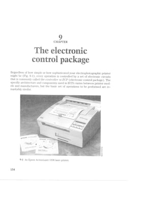
![L/OWE/I’}’L'Ll/iZ51/(}(§Ll/Z»()‘i L E 3 3
Air EC]? iiugist coinniuinicate vvitli. the outside vvorld (the user as Well as the com-
puter), and translate conununicated data—often in the ASCII forinat-—-into charac-
ters or pt1t't€l‘1lS of dots that are used to ;f'orrn an image. The EGP also directs such
physical l'.PtSl(S as paper pi.cl.<;up and high--voltage control. lt interprets sensor infor-
rnation regar'ding paper supply, EP cartridge condition, and fusing teni.per'ature. Fi-
nal.l.y, each of these tasl<s (and1inor'e) nrust be coordinated to vvork together.
typical ECP can be broken down into four functional areas: (lf) coinniunica-
tion (or ’Zl-'7’Z.-l76?'i'jlTZ.C7€), (2) ineinory, (3) control panel, and (ii) niain logic. Figure 9-2 is
a bloclr di.a.gra.rn. for typical EDP printer. Note that these functions often can be fab-
ricated onto a single PC board. Before you begin troubleshooting an EGP, you should
tlioroughljy underst.and the operations and cornponenits in each of these sections.
Optical fiber
. bcanner
t.‘_»o1u1‘0l motor"
panel “WWW
§---~'--—--—-—-D
WWW! Laser diode
=i ___“ .__. .*...
’"“ “'1 ---W Prilnzny corona/g1"i<;l bias i. 1 ‘ . . ..
l
i "l isfer corona ii
nu
ifi -CdI-"
. eont1'ol.ler ulu _ _’ _ _. _. _
1 1 . r . ~*»——— 3 l-)e-Veloplngblas
ii.‘ .1‘. ‘ ‘Z 3 . ..
l fix" V IV-lrgli-voltage
l ‘ i “vii
d@"1L'@ ‘E in-~_. |..i...,.....1 Static chzirge i
1 ---~ eli1ni.nat01' l
l »---------»----»-=-—~
if l i
I y 1 . oner sensor
1 it .
3 i D1'iver/
mw'“W"""'“ ‘ " sensor @* le11c>itlsi
l p(* """-'_"‘*‘"'"
ll in 1 y _ _ p % "-i‘
g 7 sa_,~...: 1nte1'iac.e :.u~......_..,,;.,, i i---—----<---'-—-—--—--——~i
I
-..-..--,0.“-..¢_.a
l...wg; _ _ _ ._ . . . — -- — -——7_:_:
1 I "
i l
,, __W,__.,___J .
l/__ _',~.._.;1‘i
i ;gl?1cl<-1.1p rolieri IV “hm 1- LAIE
Low-voltage V _ _ _ V -A y
pC.M,el. Supplw by lria.11| motel‘ i?‘i'(VJ(_f()llLlli.-wlilllg
mMO1. dgiWG1. c.'posure lanlps
.1.-max i ml.....
_; El('.‘. ]]O--’E§l' =
:".r:>~'~,.-""1 '1 on er sii,th (Ii n.lmmIe . .;=.-..i_
QB- “»?~=~;;r_.:____-.~ g ~_-.-_---.__.-._..__a...§ Fuser roller heat'.e1*
9-2 Diagrarn of a typical laser printer. 1—iewEeu-Packarci Co.
@®ii7i}i”iitir”ii€t‘ii.”i.itiiii.
Your printer rnust conunu.ni.cate with the outside World to receive the characters
or graphics data that i.t must print. Binary data representing this information is sent
froni the host coinputer to your printer more than one of several possible communi-](https://image.slidesharecdn.com/ozgdplurrtdj8c4ktjrb-signature-f36449d24fae8f28749ba408629a60e09bfd643da03035012a2b233e7710df3e-poli-180806114914/85/Easy-laser-printer-maintenance-and-repair-161-320.jpg)
![rue 1 ‘/ e1.¢~?ct.»"'oi2.‘z..tir (_‘.J(1NZ»-/.!'<.')Z.- iL)<ItC.?/‘i.ft!.;£]€
cation links. The computer‘ also receives conunand.s and status inforinatiori back
from the printer‘. These l‘€lL'l..ilf'lIl signais are used to regulate the flow of data. Although
there are maii.iy v‘a.i‘iatioiis of coinmuiiication liiiks, d.ata. is transferred using either
se‘2i""/ml or y'll)Ct.-'i"’(T{.-Z.l-GK; lI€Cl.“il.l.lQ_tl<'i‘.. lf>a.t.a. is sent over a parallel link as whole chai"acters--»
that is, all the binary cl.igi.'ts (_oi‘ bits) that compose a character are sent at the same
time over inultiple sigiial wires. .../-l senal link transfers data one bit at a tiine over a
single wire. Before you see the specil"ics of parallel or serial coininunication, some
backgroiind infoi.‘r.iia.‘tion is iii O."i‘Cl.€l§'. liiiperieiicecl troubleshooters can skip the next
few sections.
i-2%
5‘:
;%%¥ gififis <5fix sat’IE we as
I"“‘JW P../'1 ‘ atQ1?s 5""AVT‘_ 2»)-.11”,
we
Q’ 5
iwi iii ii‘
1 ruur eariuri grurid
A coniputer can send ee types ofinformation to a printer: (1) text characters,
(2) control codes, -and (3 “~“y;ihics data. Keep in mi.nd that not all. printers will ac-
cept character or gjrapl ’ "- "0 or i1iterpi‘et them, in the same way. Character data
represents teirt--le'ttei‘s (in any language), numbers, punctuation, or other text
symbols. Control codes are used to send coin.niands to the printer. Control codes can
set general operating modes such font style, enhancements, or pitch, but they also
can direct ininiedi.ate operations such as form feed or line feed. Using control codes
elirninates the need to opeciate control panel inanually while a docuinent prints.
Other control cod irovide the printer‘ with graphic data.U3 F2"-:4
{Ti@ihm-ii
Before any coi1;i‘u;uunication. can take place, both the printer and computer must
speak the same la1i,g‘uage--whei‘i coni_putei' sends out the character H, its printer
must i‘ecogiii2‘.e that Cll&?tl'23.Cl1€l‘ as an H. Otherwise, it Will just print unintelligible
garbage. Becaiise each cli.ai‘a.cter and control iiistruction is represeiited by its own
unique l§l.'tll§l.'l€l'lC£1i code, both printers and compi.itei‘s must use a common set of
codes that describe some ll‘lli“l.l.lll.'l.i1ill. number of codes. in the early days of computers,
each manufacturer hacl its own code set. You can probably imagine how dilTficul‘t it
was to ccunjbine eo_uu_;iii.ient made by dififerent .ma.n.ufa.cturers. As the electronics in-
dustry inatui‘ed and pl."il1lljers became more COll1l'il.O1‘l}§)l.ElC€, the demand for equip-
ment compatibility forced i.nanufa.cturers to accept a standard character code set.
The .anier‘icai.i S‘lZ&.l1Cl.El.ll‘Ci C»oc.le for infoi‘mati<3n interchange (known as ASCII) has
come to repi‘esent a single, standard code set for computer/printer conununication.
The st;ancai‘d ASCill code covers letters (upper- and lowercase), numloers, simple
symbols for pLl_i"iCl1ll23fl1lOlTl and math functions, and a few basic control codes. For ex-
ample, if you wa.i‘it to prin't an uppe;i.‘case D, your‘ computermust send the. number 68
to the printier. The prii.iter ‘woukl then lf.l'Z:l.l."l.Sl.€tl](';‘ into a dot pattern that reflects the
selected font, charact- pitch, and €i1l1£i.I‘lC({:Ei'll€l1l1S to form the letter D. To print the
word “Hello,” conipuiier must send a series ol'rui.mbe11‘s: 721, l0l, 108, 108, and ill.
Pure (origina.l) ASC-ll uses codes 0 to l2’7.
35§ecause of the way chara.cter codes are actually sent, however, most computers
also can use codes ranging from 128 to 255, but keep in mind that any code over 1.27
is not pure .aSCll. instead, codes from L12? to 955 are sometimes called an Ctl‘Z6’l"'l’?.6LZ‘€
,......;...,.
,_-53
1*-:
i.](https://image.slidesharecdn.com/ozgdplurrtdj8c4ktjrb-signature-f36449d24fae8f28749ba408629a60e09bfd643da03035012a2b233e7710df3e-poli-180806114914/85/Easy-laser-printer-maintenance-and-repair-162-320.jpg)

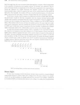
![169 T/is 6l€OZT‘7*"O7‘Z?.i-C CO’l'Z.,l§’}"O[, pcic/irctge
Qoniinanicatien standiiitis
Th.ei'e are litei*ally hundreds of Ways that you can iniplenient a coniinunication
interface. You can believe that great many ve1'sion.s have been tried and abandoned
since the early days of coininei"cia.l printers. The evolution of technology favors the
best methods and techniques, so those that vvorla vvell and grovv with advances in
technology can sometimes develop into standaids that other inanufac't1ii'eii"s adopt in
the flll1Lli'€. Standai'ds aie basically a detailed set of rules and peiforinance Cl"l2lI‘EtC~
te1“ist1i.cs that clearly dei’ine the constniction, connection, and operation oi’ a cii"cuit
or syste1n--in this case, a coinniunication interface. By adopting an established sta.n-
dard, inanuii‘actu1‘ers can be Stll"@llllflfllpl‘l1l.l1€1‘l)l'&l.l1ClY will operate fine with coinpiitei"
brand X, and vice versa.
Pairallei eoinninnieatioii
A parallel coniniunication linlt l“€qLl.l.1'“€S tvvo sets oi’ signal vvires as shown in Fig.
9--i. One data line is needed for each bit of parallel data (usually eight lines). A
ground Wire is oiften supplied as a separate return path for each data line. The llovv
of data also must be cooi'dinated with the coni_pntei'. The coordination is accom-
plished through a series oi’ [ZCI/,}4ZC£S/)2/(zikp/£7V2/Q lines. Both liandshaking and data vviring is
routed to a l’einale COl1l1€?CtC)l" inounted on the printer. This connector is attached to
the coinput-e1:'ovei' ainnlticonductoi‘ cable. The diagiain of Fig. 9-5 shows parallel in-
terface hardiva.i'e in more detail.
_ ;l11itial_ize WA
Stmbe
l 9 T T “T T’
l i ~5rW1@1?@@<l it " it
%g_ Ei'i'o1{_W _ p
lg Select _ fii
C3oinpul;ei' ‘Q c_t y_ A-‘C1'--.11‘i>~"’1§(1§i@, H__ P1"inte1'
- Bnsv
as
l
‘ l1 l
‘ DL'l‘1 Q bits ‘. A . _ .1 . L IL ,_>._‘ I
. 7 > i ‘ was ‘ l'=<i%“'-“-14v '--'">. ">-‘~?v."=H-' -1» -11:»‘4'~f=»=‘-»’im颒~~; win»».-,w:~".r-'=-,~ ‘Iv-Y 1-;v,=v~.>:1¢ -';».-:>,:-W-.. -1 ' ,-ml-‘= '.m J ~1'¢‘.:»‘v‘~-::~;m.7,:'s:i ,-‘ix 1- :v~;~r~_~>-.~' =1:w“.:~,-1 ,~.-.‘~i1, .
*1‘! I-='»":~'~'¢i'>w~.’-ills>:l%»-111:--??@"I1=s.‘ v»..~:>.a=1>lz'13it2i%2:~isi‘e “=t‘::~l,1.-:=~E-‘=i.';:i=:=1~‘¢>:z=m1»»w¢¢&>i5i:>x<1amrzll=. lvlzziltil v-i11i1‘=~=>.=:"~:I'£:»~w=
i
E11?“
Gi'ound
9-i Data and hanclsl‘ial<ing lines of a 1)El.I‘El.ll.€l poi't.
When the computer sends out a cha.1‘acte1', it places all eight bits of the chai'-
actei" on data line DO through D7. Data fi‘O].'l1 the computer‘ follovvs the standard
conventions established for TTL devices. A logic O is I’€pll'€S€l'lll€(1l by a voltage
level between 0.0 and +0.8 Vdc, and a logic l is 1'epi'esented by a voltage betvveen
+2.6 and +4.9 Vdc. You can easily ineasuie these voltages with a logic probe or os-
cilloscope. The timing diagram in Fig. 9-6 provides a good illustration of parallel
port operation.](https://image.slidesharecdn.com/ozgdplurrtdj8c4ktjrb-signature-f36449d24fae8f28749ba408629a60e09bfd643da03035012a2b233e7710df3e-poli-180806114914/85/Easy-laser-printer-maintenance-and-repair-166-320.jpg)
![L1on,necto1_‘ L + ..l-*'(_1¢-_ E
P'7""Z:-’l‘Z.-Ke?'7" C30’?‘}“'2/l‘7’Z-’Z..t»’7‘2,»’Z1CCt-ZI'2:-O‘?'"Zl Z)(TLC?/{IQ‘TO'2.t/T2‘-Ct
“)0 _ e - __._l‘______ii
-,/I to-
,,,,,,,,,,,
l
.-
4
Q
._Q,-'
‘ ~. 5% s l“' m ‘M’ T Pal a
»./~_.'=
1l l 1 _ 3 _ . 1 > ,-
. latch 5 T i Abus _
Ty? .
i. . “is
as iiiiiiiiii - .
gL_*_ Auto l.il1_"' _ _
;_, ---v" ‘ p "" " * I sq A;
" O tiuil
lsal1Pl'11 I U 1)
ls g ~_meiia.li.>le
’‘{*T(f} Paper out lllllllllllllV 919$‘_%_______._ ___ ~ K I . . . .
llli‘:-153:1-lz“ - Supp<:>i‘t.i1ig
l i~'-;rl' ‘~’lE%Yl,Q€
svsosee l “mm i‘ logic
V A;(_“__[: --- _ --
ignsy ._ - ii
. iili,i_Iie¢‘=;eil;
_ T Paper
sensor—--w--——-~'-<§;§_flH—:—— 1&1-—-—-———-—
§l->ata
bus
it»
$1
slié
tit“!
-.>-»-Qi"Ks:W »- .---4‘ <'./
‘l VW
,.
» ..1. _l
itav.
1l’- it
2‘//~
ll I
,l C
.~.~ - w .'1": ‘"75:V 6.».
l /
1.‘? CV
,2?’
In 1 l‘-P1
i
i».¢_
data
§
a’
ti
I__
‘fit
. l
.sh (55 la
~» xiii1’Q. A
its
it
{-
I‘
<.I§oniie.cl'..<;n'
15 "'<jl<1'
control
awggi.
" 3
V, s i:§e<_i:on<;.lai'y C-l~ U
1 SEL W 9 """”"”” "T
l
A
c'aouiii:> --------- I 01‘ *“‘“%l(3
9-5% Sij1fnplii’ied d;ia.g1‘ain oi’ a ‘pa.;1?al.l.e§l. c.onun.u.ifiieation cii'cui.ii-.
_ 0 _ so Select
lnitialize
M ei"l1o1‘»'
“lg RA.ii/sot-=li A
signals .
E’ Busy
TT ll
a -......_ . _, . fi:-=---<-»»- -- - V------~—-= *"'-**-?<-- I-"~'—=-'** Y
.#.cl<.n.ovvleclge i Ii
Pti selected ‘l l.lev data 1.*equest
O0 ../
DAT L (DG_D mm“,asiiiiiiéeiiiiieiziaiaiasisieisizézisésieéeizaiiA
l'I1"1—~I‘r'. H _ _ _ _
.15§1_:11§:§:§:§:§:§:§:§:l:?:1:1:i:¢:11=:§:?:1:?:§11:§:§:-.
________=___ ____ _ Hi... a-Ywwwmu» — ___,» —
Data g__ __ V V ____:__ ix “Tum V if
ti*3_,1n_5;f@1* St.-l‘C1l,)€ l l p a i
signais ttttttttWtttttttttttttttttttit , T
Busy i l / it
./ ‘
LXCFO fl3_1O_ _ _ _ A M A1 / ‘ T New data lcialilecl
“H R 9' LL “Gk UM d‘1'm 1')1(')C't'bbt'(* ‘New data. available
Neiv data 1'e@o_i,1est
Piocessing data
7:)? "3" ‘ s _ ’ " - _ __ __ ,“
1* “ll»)U' Om‘ ]:’a]_)e,i,' out / F Papelf ieplacetl
Ei'i'oi' _ ""'****s" W‘
signals Select l _ O1‘"1m‘1‘ U1
se lect ltev
pi ¢- sse< l
k J H I
Bust’ l l P
9-»(i Parallel-port timing signals.
;-ma @ gm-‘=i](https://image.slidesharecdn.com/ozgdplurrtdj8c4ktjrb-signature-f36449d24fae8f28749ba408629a60e09bfd643da03035012a2b233e7710df3e-poli-180806114914/85/Easy-laser-printer-maintenance-and-repair-167-320.jpg)
![i ea This 6?lei?Z?TC)"ll-"'2./tcf (i?O“l~“Z.i[‘i"'Ol- _pcfi..rir/wage
When all bits are a.vailaili>l.e the ij1.ii;ei"face, a Strobe Signal from the com-
puter causes S'L'l}_I)pO_l.‘l1i.ljlg logflfli to erate a pulse. This pulse latches all data bits into
the printer. at this poiiit, the computer can send aiiother character, or go on to other
ivorlr. al’tte@ir' the printer receives a valid strobe signa.l, its microprocessor circuit reads
data onto the printer dat.a. bus vvhere is stor"ed in segment of temporary memory
called the (t-ct.-li(Tl‘..- b For an Ylilll? pi‘l.Il1’l.‘lT-El‘, the data. buffer can be up to several
lnegabsytes depending on how .l.’ll.'t.'l.Cll ;1.neinoi;*y is ;l"itted to the pli‘llll§€I‘. During the print-
ing process, cl;ia.racters reiiioved jtroiii the data butter‘, processed by the micro-
processor. then outpirt to the »V,l_‘lil1l.ll.§i5' mechanism.
r’lt1lic>siigil"l the pr.i.nter is accepting and storing data, it sets its Busy Signal to a
logic l level. coinpulier >vill not strobe any more characters vvhile the busy line is
ll. .a_;t‘lier data is stored stuc.c1essi’ully in its data (buffer, the busy signal Will be re-
leased to a logic O, and its .#cll<novvfl.eclge Signal vvill strobe briefly to request another
chara.cster. Once an a.cl<no>vler.lge is generated, the computer can then send out anew
clia.racte.r. This cycle is repeated until every character is sent successl’ul.ly.
lr?.ealize@ that the tra.nsl*er of data iliiettveeii. computer and printer occurs indepen-
dently oi’ its interpretation and printi in practice, comnuinication can take place
much ii’asteir than El...lil.§;’ jprint.er can i1irii.it--that is Wlllfy a data butter is provided. A
printer can accept cha.i'acters in large groups, then operate on those characters un-
til the lni.it'i'ei;‘ is einpty. ll? the il;ru;tt'er is not .la;ifge enough. to hold all data, the computer
tvill stand by uiuil the bufl"er is e.inpt.y; their send another? group of characters. The
t1irn.i.ng of data t.ransil.’er is conlirolled ei.ithfeIl.y by l'l3.fl1(lSlil.£1lilIlg lines.
9'9F3
‘>....: F...)
0'0.
sax/$5‘ we-¢-2%
S€lf'Il.£Etl.—COij'l1l.'ljtt.iljl.'ll.Cidft-ll)n linlr e§xil"1ibii;s slightly C‘l.ilfT€:if"€l§llT, characteristics. in the se-
rial circuit oi’ Fig. there are only two ciiata-carrying lines: Transmit Data (TX) and
fl3i-polar TTL ii
signals signajls Dillfl
bus
' X ml My" l/Iemorv
___(f) _ @-‘~’ 1‘ ‘
’ "" _=A.xb.].(./ '°<'¥'l'i"
siegl.. w$;‘§§Yr7,
C<'3»~.»-~
I £1‘f~»/E53.>‘-(“Kirif§.E-|c;.3/ll
. . f- fig’ 54'
i 7 V 7 ’-‘:- V V H W7 777
i § t
Linei ‘ ‘ i ( »ontrol E. 3 _ _ - _ _ 1 w '- * ~ ' = ’,;r:g
Ra: -;-i. receiver ... ...._ ll Q3.
1 - ..................ii xiii
Gifotiingl “___! 1-L’ L N
T E 5 W” 'tili1R.'ilf‘ Devi. gag ~ l
' _ _ . g ‘iizilfilll- - » .,-._;.., ,llE"':Eg‘1 7 ,
. ~ 1 " *1
T is-l Line »- Mm
__ my T "transrnitt.er .¢
D l. P. ~@i—~- ~- ii“-——
lb - -
DIP
I ,. ., _g strf.ltii.C{lieS
i,-onnectoi‘ "1" 13 -1" dc -----
+ 9 Vclc:
' * 9 Vcllit
l;A
"fix........ L"_“*"'——i_'i
i,...
%“**T:~»;~j"~'>
ii
.aa
iii»-'7 Siiiiplifiecl diagram oi’ a serial communication circuit.](https://image.slidesharecdn.com/ozgdplurrtdj8c4ktjrb-signature-f36449d24fae8f28749ba408629a60e09bfd643da03035012a2b233e7710df3e-poli-180806114914/85/Easy-laser-printer-maintenance-and-repair-168-320.jpg)
l‘c'.l.I‘---l1l'l2?l.'t~ is, one logic level is
represented by a positive voltage, and the opposing level is represented by a nega-
tive voltage. This l~Il.l1Cl. of bipolar O]J€I'&'l§lOll allows serial inter;t'a.ces to carry data over
greater distances with less noise than parallel intei*i’aces. Although Fig. 9-'7 shovvs
bipolar (loosely referred to as Clfl“'Z.-CLZVOQ) signals ranging froiu + 9 to -9 V, a serial in-
terface can use voltage levels ihfoin :5 to .-i;l5 V. You can ineasure these serial levels
vvith an oscilloscope.
Unfortunately, bipolar voltages are not coinparable Witli the digital logic devices
at vvoi'l< in the printer, so data and handshalring signals must be translated between
bipolar and TTL levels as reqiiired. This ti'a.nsition is accomplished by a set of de-
vices lrnovvn as l/me ti'u..itscetiiers. For example, bipolar bits received from a com-
puter aife converted to TTL levels using a //Z.fl’2.€ 'iirr"ece?}ue'i'"', and TTL bits must be
converted to bipolar levels using a I/zine Ct'i"’Zli.?€’l".
The problem vvith. sei;'ial data is that it can only be transii'er‘r‘ed one bit at a tiiiie.
Each bit must be assembled into a complete character before it can be stored in
memory. Just the reverse is true for control codes sent back to the printer: .A char»-
acter (usually eight bits long) must be disassembled and sent as a series of individ-
ual bits. This tasli of data manipulation is handled by a specialized lC that can
pertorm these conversions. The basic name for such a device is a U.Al¥.T (universal
asynchronou.s l‘{~?C€lV€-31'/'tl‘Etl“lS1llll.l]ll61"). Not only does a U_/~;l?..”l." pertorin data conver-
sions, but it also can attach or remove the overhead bits of a serial character. Over-
head bits include such things as the Start Bilz, Stop Bit(s), and Parity Bit.](https://image.slidesharecdn.com/ozgdplurrtdj8c4ktjrb-signature-f36449d24fae8f28749ba408629a60e09bfd643da03035012a2b233e7710df3e-poli-180806114914/85/Easy-laser-printer-maintenance-and-repair-169-320.jpg)
![rue J '/ze e’?li(:3(.?Z§‘}‘O‘l‘Z/Zi-C C0'l‘2.»fi‘i”‘OZl pcickrctge
Wl‘ie1i a bipolar bit is received by the printer on its RX line, a line receiver‘ trans-
lates it into a correspontling‘ TTL level. Each bit enters the UART where overhead
bits are stripped aiivay. After an entire character has been assembled, the micro~
processor circuit accepts that character onto the printer da.ta bus, where it is stored
in the data. buffer to await furtlier processing.
l/lost serial. pl'l§ll'lI.€lj‘ interfaces operate in either a hardware or software hand-
Sl'lE.tl{lllg mode, and communication caii be coordi.nated with discr‘ete signal. lines
(such as DTR in Fig. 9-'7) or control charactei‘s sent back from the printer. A char-
acter to be sent must be loaded into the UART. The microprocessor‘ determines
which character to send, then writes that character over the data bus. Once loaded,
the Cl.l8,l'Ei.Cl1€l.’ is disassembled, ov‘erhead bits are added, and each TTL bit is sent
tl1u‘ough a line driver lC. The line driver translates each TTL bit into a corresponding
bipolar bit prior to leaving the printer.
isnlaring the cernruuriieatiuii iriterfaee
conununication interface involves much more than printer circuits. The suc~
cessful transfer of data requires proper operation of a computer and interconnecting
cable as well. Trouble in any one of these three areas can interrupt the flow of data.
Before you disassembl.e your EP printer, you should isolate the problem to the printer
itself. The qiiicl<est and most certain way to do this is to test a working printer‘ (one
that you know is working well) on your existing coinputer using the same parallel or
serialinterface. lf a woi.‘l<ing printer works properly, then you have ruled out the com»
puter‘, cable, or softwa.re program. lf a VVOlj"l€l..l.'lg printer also fails to operate, you might
liaye a problem in your computer, its software configuration, or the cable.
Once you have isolated the problem to your printer, run a printer selfltest. The
self»-test wil.l test the printei.‘" motors, memory, writing mechanism, power supply, and
iiiost of the ESP. lf S<i~?ll3—l]€Sl1]3&lZl1@I‘ll.lOOl{S good, you can be pretty certain that the
pri.nter intei‘face circuit is defective. If the self-test pattern is faulty, then your
l3I'l1l.‘C€fi§" is su.ffei‘ing‘ fro1.n a defect elsewhere.
"ilrnuiesiiunrig a araiieiireriaee
dyiiiptein P‘i‘"2I'i“2,Zrer‘ does not ]9‘7""’Z'»?"'2,Z§ at all. Tlzere inighzt be ct PRINTER NOT
]%.EAl)Y cli'21spla;gecl on the £01?‘/.2/ti)‘/‘OZ pcmel. T/‘re p'7"’Zl’}‘7,-fi6’?"" selfltest loo/rs crorrect. Be~
gin by €XEl.ll.lllllil,§§ your‘ .'rnter.face cable. lf it is loose at either end, data and handshaldng
signals might not reach the printer. lf you have run another printer successfully using
your curreiit cable, then the cable is almost certainly good. If you are in doubt, try a new
cable. lf you wish to check the origina.l cable, disconnect the cable, and use your multi-
meter to measure COl‘1flllll.Ult,V across each wire. Wiggle the cable to stimulate any possible
intermittent connections. Replace any defective interface cable. lf you do not have the
tools or inclination, to perfor.i.n detailed procedures, replace the printer’s ECP outright.
Disassemble your printer a.nd expose its communication circuitry. With the
jprinter connected and running, use your logic probe or oscilloscope (as shown in
Fig. 9-9) to €XEtllllll€ each li.anrlslial<iiig line. Table 9-1 is a listing of typical pin as~
signments, but refer to your users manual for the specific pin designations used with
your parallel interface. Connect your test instrument to the signal ground (SG) line,
then measure each of the handshaking signals in turn.](https://image.slidesharecdn.com/ozgdplurrtdj8c4ktjrb-signature-f36449d24fae8f28749ba408629a60e09bfd643da03035012a2b233e7710df3e-poli-180806114914/85/Easy-laser-printer-maintenance-and-repair-170-320.jpg)
![.’l'"';“‘o~u,bles/toomtg as ]3Cl'/l"CL(tel '20 ztei](tC6 "f 65
“ -;;‘-‘E-',-'Q‘-,‘-*,-'E-‘,-'-"-~"-- ‘ .:::::::::::.......::
P ...............................
;§::::::::::::::::::::::::::::::::::::::::::::::::::::::::::::::::::::::::::::::::::::::::::::::::::::::::::::::::;i
»'::: vmmwwmwwmawmvrwmwwww :::::::::::::::::::::::::::::::::::::::::::::::::~"; ::: 1.-----~----Q-ax-~~'--~'-~<'~-<-~--'---"--~-"~~.--~'~-.-'.;- .'-::|:-:|3:“.-..............».--...............;
E ::: 1
I iii Z1 ‘
; nzki
l" ::: -
,.._|m.,_
‘:~ ::::
3 I22:
22;: I t5' ::::§ 1»
r
mm “:::, :::‘::::::::.:.-..-33; -::::::::::::::::::.:::: :::::::::::::::. ::::::.........:::“ "::: ::::::::::::::.::......... ::::::::............................
‘rm-new “"'“'“ ::§::::::: 2,
3
1I ,._._._._.,._._._._.;_._.‘._._._._.'._._._,'-.._.,._._._-.._._..'.'.'.>.'.'.-.'.'.'.'.'.'.'.'.'.'.'.'.'.'E.'.'.'.*.'.‘.'.*.'.'.'.'. ~» ‘J'T*.'Z.'-'.'.Q.'.'.'.'.‘.’.‘.'.'.'.'.'.F.'.'.'.'.*.'.*.'.'.‘.'.'.".'x'.'.'-'1
iiiiiiiiitdlI]@fl§f'l.lII§l.@i§fl.,.(111.1flllflfilliiIflll.§ll1§.lfliiiiiiil'
8') '
Centronics
parafl.lel.-port.
connector
Table ‘9~"i. Piii assigiiiirieuits
an
13 W h ___, _ Testingaparallel-po1l connector
fur a typical parallel iiiterfiice
Pin nuiiiiber Signal
l
0
E’,
P)
6
'7
8
9
tetra
—r
OJ
HI»
C'.'R~U OD
L'JDC»3C;I>C=l)4-‘ i-Q-L3l—-*CDL'JOO'l
LD L3
C13 OT-
Suobe
3maO
llata 1
Dma2
Dma3
oaaa
Dmab
ikurio
Dma7
.Acknondedge
Brmy
Papercuu
Select
.Auu3hnefeed
Signal ground
FlI'&li1€ ground
+5 Vdc
Data. line grounds
Pi‘i.me ground
lnitia.lize
Error
Name
DO
Ill
I32
D8
D4
D5
D7
BUSY
PO
SEL
AUTO
SG
FG
PRIME
ERROR.](https://image.slidesharecdn.com/ozgdplurrtdj8c4ktjrb-signature-f36449d24fae8f28749ba408629a60e09bfd643da03035012a2b233e7710df3e-poli-180806114914/85/Easy-laser-printer-maintenance-and-repair-171-320.jpg)
![.’Pro'ttbLeshooirrrirzig ct serial ’zl1'2,tevj‘]“cz’ce* l 67
missing, there is a pZ£‘Ol)lE?ill1 in your supporting logic or ASIIG. Check your su1.iporting
logic or replace the .ASlC. ll’ you do not have the schematics or test instruinents to
perform this type of troubleshooting, replace the ECP ou'trigl1i;.
rmMWe@
a e ‘gt
esuarrrag H serra rii.rtt.,@
Synapteiri P*s1’"mtevr" does not opglaemte at all. A PRINTER NOT READY er"/2"'o*1l"
might occur at the prt1r'2,l;e’2r': T’/re ,prtrl2.ter seljltest looks cor2""'2l*'ect. Your first step should
be to check the conununication interface cable. lf it is loose at either the printer or
computer end, data and h.an.tl.sjhal<ing signals might not be able to reach the printer. lf
you have run another printer successfully using your existing conrputer and cable, then
the cable itself is alinost certainly good. To verify cable Wiring, try a new cable. lf you
Wish to test the cable, use your .T.'I.1Lll.lj-llll€'C€li' and rneasure continuity across each cable
Wire. Be careful here-—nrany serial cables flip (or reverse) the TX and RX lines between
computer and printer, so you must consider that when making P£1€EtSl_ll"€1Tl€l1lZS.
Serial coinnuuucation requires a fairly large .nLun.l;>er of pararneters to specify the
structure and speed of each serial character. Word length, stop bit(s), jparity, baud
rate, and handshalcing method, are some of the more conunon options that can be se-
lected when setting up a serial congununication l.inl.<. Howeveii‘, each option must be set
exactly the same Way at both the coniputer and printer. lif not, a printer cannot inter-
pret just Where data starts and ends. The resulting confusion Wil.l cause an erratic ju1u~
ble of unintelligible print (if it prints at all). Conununica.tion paraine'ters are usually set
by software, or a series of_funipers or dip switches Witluli the prtnter‘. Check these set-
tings against those listed in your user’s inanual. ll? you have run another printer, checlr
its coni’igura.tion and compare settings. lf you do not have the tools or inclination to
perform detailed procedures, replace the pi'inter’s ESP ou.tright.
. . . ; - vnvx-... . - . .1 =Yf!’'!‘?T‘1'l rrir-*?‘i1‘fi<rrv':TrF€|"I'ri' -rs-vrv . .v-1-n T. . . > . . . . .'-1.‘. .'r.‘F71
un-r-1:11o-1--:14>vvov~~n>>nq»@|qnp|~»a:u-nuuuoznuuuv-anI
1:4 ,~.-......-~.~..........~~1|.-..-.1||.-.|~....-.----....;
1: __ ................... .-_ ..-.-..-..-~-.....-»-... _:
1 .'. 1 T ;.,‘.‘.'.'.’.'.'.‘.‘.'.'. . . . . . . . . . . . . -;_ _._ ._ ,‘ _-,-_._._.|._-'-_-_._»_._-_._.'._-_._.......'._._.'.,__
;"-'1 -; % Z;;l'»"'-'.'»'-'.
;'.'|; l. .;.,.-...--_.._. Q ‘....-.-
;‘.‘.; -¢ ;.;...-..-
' '.' '4 ~ ' -'.'.'.'-'-'.'
1 | . ; l 1_ I 1 - - ‘ - 4
[1 .‘. 1 ‘ <{.:'.'-'-'-'-'¢'-
..._ ._........
..,., » _--_-......--.-._._ _. g , ._._._.'._._._._._._._.
- , ;._ -.. it ..,. ~-~---1-=~ 1....-..--....
, . - , .. . ._._.‘.’.’.'.'._._.'.|._._._._
Q -I- :1
l; '.' ‘; ; .‘.'-'-'.'.‘.‘-'-H'-'.'.'.'-‘.'- 4 .
‘j .'. 1. .;. '-'-'-'-‘-'|'._;...‘-H-|.l1_'<'-'.°.'.’.‘.‘.
' .‘. ' -1 '.‘.'.'.'.'.I'I .‘.'.'.".'.'.'.'.‘.'.'. . .3-}. -_--....a..-............: ...’. :_ '.'.'._.‘._[--'- i__;_._. -.-_-_-_-_~'...‘-
» :34 s{ tn-.~H-H--A-='.'.'.'.'.'.'.3-..-{ ; ,2;......!‘-._‘.:....... ......_._. ‘... ...-...;..- ...l...
;..; ;~'.-....-....L.'...-._....i......~l;~. ...‘ ...'...‘_..................,_; . . 3 W" ._.'. . . . . . $1........‘._‘_,,i,,i_,,‘.'._._...‘.'!_;
"-'.-...--...'>.--I-..'.-.. » ~ ..-‘...------I-.......................... ,..-..........._.
.._....,................... -........:fi:'_‘_r:
H-:ZEQLL"‘?vt i ‘Ni l""!1* "'4iiLi ..4:l‘'‘4 7.. ,....
~aaaaa»-MWaaaaaa~- Sub1n.iniature
‘ D-type
13 l connector
.............
L 1 4fL'J J!
Subniiniature
D-type
connector
9&9 Testing a serial-port connector.](https://image.slidesharecdn.com/ozgdplurrtdj8c4ktjrb-signature-f36449d24fae8f28749ba408629a60e09bfd643da03035012a2b233e7710df3e-poli-180806114914/85/Easy-laser-printer-maintenance-and-repair-173-320.jpg)
![iea 11 '/are e£iecti2ri'c>/mic CIO"l‘Z=t‘7"O[- p(.fz.c/rage
Disassemble your pI‘l..I1’f<€I‘ and expose its communication circuitry. With the com-
puter iuniiiing and connected, place your printer on-line, and use your oscilloscope
(as shown in Fig. 9-10) to measure the activity on each handsha.l<ing line. Hand-
sliakiiig lines of pi'i.mary iiiterest to serial printers are DTR (Data Terminal Ready)
and RTFS (Request To Send). Note that RTS is simply ignored in many serial inter-
faces, so concern yourself primarily with DTR at the printer. DTR connects to DSR
(Data Set Ready) at the printer. l5‘i.gure 9-ll shows a typical serial link. Remember, if
your printer is set up to use software handshaking, it might be unnecessary to in-
spect hardwa.re lia.ndslral<ing lines.
Computer.‘ Printer
£
43
4
*2
'_I >/»
DOC/L‘
is his
L.2 C?DSH ' § DTR
7+" H 7 C-}i*oiincl 1 7 ,
L T‘ —--i-_----.................i___
9-il Dl£1O'1‘&11l of a. lZf]lCté§1l seria.l connection.O .. .
Serial signals at the interface connector bipolar. If the printer is ready to re-
ceive data, its DTR line should be at a positive voltage (+5 to +15 V). A negative volt-
age (-5 to -15 V) iiidicates that the printer is not ready, so no data will be sent. If you
have a schemati.c diagram for your printer, check the line driver circuit, and the sig-
nal from your Lilli-R7f (serial data functions can be integrated into an ASIO). You will
have to refer to your 1.'>rinter schematic, or manufactur'er"s data for your specific lCs
to Cl€l1€li'1.1li1.l.€ which lC pins serve input and output f=.1nc'tions. If you find a faulty
ll.&.I1ClSl1Eil{lif1g line, replace the defective line driver or UART (or ASIC). If the serial
port appears faulty, you also might replace the ECP outright
When your hanclshalung signal is correct (or your printer is configured for soft-
ware handsha.l<ing), place your oscilloscope at the printer RX line and try sending
data. from the computer. You should see characters begin to arrive immediately, so a
random square wave varying from a positive to a negative voltage should appear on
the oscilloscope. if this sigiial is absent, data is not reaching your prin.ter. Check the
conditions of any other han(;lsha.l<ing lines that might be incorporated into your par-
ticular serial interface, and retest the printer.
Use your oscilloscope to mea.sure data into and out of the line receiver IC. You
should find bipolar data signals entering the line receiver, and a corresponding TTL
(O to 5 Y) output from the receiver. Refer to your printer schematic or manufacturer’s
data for your particular line IC to find specific pin functions. If data does not leave the
line receiver, replace the defective lC or replace the ECP entirely. TTL data signals
also should enter the UTART. if signals enter the UART (or ASIC) and the printer does
not function, there might be fault in the. l-lART (or ASIC) or data buffer memory. Try
replacing the UAR.'l“ (or ASIC), or replace the data buffer memory lCs. lf you do not
have schenratics or technical data available for the printer, or you cannot test or trou-
bleshoot the serial conununication circuit, simply replace the ECP outright.](https://image.slidesharecdn.com/ozgdplurrtdj8c4ktjrb-signature-f36449d24fae8f28749ba408629a60e09bfd643da03035012a2b233e7710df3e-poli-180806114914/85/Easy-laser-printer-maintenance-and-repair-174-320.jpg)
![i 7h The 6Z-QCt"i"'O'7‘2/Zltl? CO"7*"Z;ZI'7*"Ol- pu;c/ircrge
A ROM is the oldest and most straightforward class of permanent memory. its in-
formation is specified by the purchaser, but the actual lO must be fabricated already
programmed by the lO manufacturer. ROl/ls are rugged devices. Because their
program is actually a physical part of the device, it can withstand a lot of electri-
cal and physical abuse, yet still maintain its contents. However, once a ROl/l is
prograinmed, its contents can never be altered. if a program change is needed, an
entirely new device must be manufactured with any desired changes, then in-
stalled in the circuit. ROl/ls often used in font cartridges that are manufac-
tured in high volumes.
The PROM can be programmed by a printer manufacturer instead of relying
on a ROM manufacturer to supply the programmed devices. A PROM can be pro-
grammed (or burrrzrail) once, but it can never be altered. Factory-fresh PROMS
are built as a matrix of fusibl.e linlis. An intact linlr produces a binary O, and a
burned linl< produces a binary l. One linlr is available for each bit in the device. A
special piece of equipment called a PROM Programmer is fed the desired data for
each PROM address. it then steps through each PROl/l address and burns out any
links where a binary l is desired. When the PROM is fully programmed, it contains
the desired data or program. One or more PROl/ls are used to hold the printer in-
ternal program.
An EPROM can be erased and i.'eprogranimed many times. Binary information is
stored as electrical charges placed acifoss MOS (metal-oxide semiconductor) tran-
sistors. One transistor is provided for each bit in the device. An absence of charge is
a binary O, and the presence of charge is a binary l. Programming is very similar to
that of a PROM. An EPROM pl‘Og1lI‘%;1il1].l.i€i“ is loaded with the desired information for
each location. lt then steps through each location and locks charges into the appro-
priate bit l.ocations. To erase an EPROl/l, you must remove charges from every bit lo-
cation. That is Z-iCCOlilpllSll€:Cl by exposing the memory device (the die itself) to a
souifce of short-wavelength ultraviolet light for a prescribed period of time. Light is
introduced through the transparent quartz window on top of the IO package. You can
tell an E-PROl/l by the clear quartz V/'l.1iClOW' in the lO.
Teniperary rriernery
Digital inforii.iation contained in temporary memory can be altered or updated
frequently, but it will only be retain.ed as long as power is applied to the device. lf
power fails, all memory contents will be lost. This ltind of memory device is referred
to as i.ioldt'zI[e, "T661/C1l~2.L/"7”’Z-Z6, or RA,/l/if (random-access memory. The term r'cm.olo'm CLC—
cess means the device can be accessed for reading or writing operations as needed.
The two basic types of P..AM that you should know are static and fill]/i'LCL’l7’Z’ZC.
A static RAM (SRAM) uses conventional logic flip-flops (called cells) to store
information. One cell is provi.ded for each bit. A read/write control line is added to
select between a read or write operation. During a write operation, any data bits
existing on the data bus are loaded into the cells at the address specified on the
address bus. if a read operation is selected, data contained at the selected ad-
dress is made available to the data bus. Once data is loaded into a static RAM, it
will remain until it is changed, or until power is removed. SRAMs are used heavily
in printers.](https://image.slidesharecdn.com/ozgdplurrtdj8c4ktjrb-signature-f36449d24fae8f28749ba408629a60e09bfd643da03035012a2b233e7710df3e-poli-180806114914/85/Easy-laser-printer-maintenance-and-repair-176-320.jpg)
![Co'2rz,tr'ol pcmeli i7i
DRA1li£/i (Clyi."i.El.li;1lC RAl~/.l) devices use small MOS cells to store data. in the foifni
oi’ electrical charges. Al;tl.iough reading and Writing oper'ations rernain virtually
identical to those or {:R../~'l/jlsj Dl§’tAl»%l1s inust be rei’i‘eshed every few 1i1l.l.l.llS@CiOliClS, or
their data will be lost. l~?.eiTresh is provided by a conibi.nation oi’ e>~:ternal circuitry
and circuits V-’llTl7lliii the DRAM chip itsel;i. r‘ilthoiigh the need for refresh increases
the cornplexity of a nieinory ci_rcuit, l/IOS technology oli'jl'ei's very low power
consuinption and large ainount of storage space as coinpared to most SRAl/l
devices.
v '.I
/"X3
"ireiihiesooririg
l/leinory is usually one of the inost relial -e sections oi’ an ECP, but when a failure
does occur, the results can rnafnil7est thein — — s lost characters, occasional oper-
ating hang-ups for no apparent reason, or up i'ron.t. initialization ilTa;i.lure. The dii’iiculty
in testing inernory is that it is virt.ually inipossible to tell for sure just Wlirat location
or bit the problem is coining froni. To test a it/~l/.l device properl.y, known pattern
oi’ data would have to be Written to each location, then read back and compared to
what Was Written. if there is a niatch, that location is assumed to be good. It there is
no match, that location (and the entire IC) is defective. Most printers peribrin a
rneinory check on initializa.tion. Untortunately, there is no Way oil? perlbrining this
sort oi" test in the printer during normal. operatioii.
ROM devices are alrnost as to iiiicultt to test. achlocation would have to be
read and a ch.ecl<.siiin value Wonl l'l.€lJV€ to be calculaited based on the contents of
each RON-i address. The calcullated cliecksinn is coinpared against a cliecksuni
value on the Pi.Ol/l. ll’ both checksuifn v"al.ues inaitch, the iR.Ol/i is assumed to be valid.
ll? there is no inallcli, the l§iOlx/i is cil.efecttive. fl?3.0l/its are tested With lr?;AM When the
printer is ii§1.ll}l231.l.l.Z€Cl.
As a result oi’ these testing dil’i”iculties, tliere are no specific test procedures for
ineniory circuits in part.icul.ai.1 This book suggest;s the I.‘€§]3l2EtC€i'Yl.€I1l'§ oi’ nieni.ory de-.
an (UL))--u-|-_-J<C3 Uz- ‘Q-7
QM,.._.._
vices on a syinjp'toniatic basis oiiily when otl;ier Syil1i§l.pllOl.'iLiS point to the possibility oi
a lil.€l'i}‘1OI'}” :t‘ai[lure. i‘-lthough niost 1i'i€i1‘iiOIii'y probl.enis will be detected and reported
during the printer‘ seliltesiz process, nieniory can tail spontaneously during p1f'.l1"il)€1“
operatioii just like ai'i;y other active coinfponent. Troubleshooting procedures in other
sections oi’ this book suggest i>vhei'e and iialieii to suspect. i11€1Ti10lj'yp};‘Ol)l.<-31118. When a
ineinory problem is suspectted, inei."n_ory devices can be replaced syst;eiiiai;ical.ly, but
it also is acceptable to replace the GPentii:'ely.
Qonirel pariei
The printer control. panel is the user li1'l1€i'l&C€ between you and the printer.
First, it allows you to operate certain iinniediate functions such as forni feed, paper
stray select, reset, or on/oil? line. Certain key conibinations let you alter options and
running inodes (your users manual Will specify the exact key strokes and their ef-
fect). indicators and LCD-alphanunieric clisplays also are included to display various
printer status conditions or error codes. Fl.g”Lill‘€ 9~l2 shows a sirnple block diagrani
for an EP printer control panel;
1](https://image.slidesharecdn.com/ozgdplurrtdj8c4ktjrb-signature-f36449d24fae8f28749ba408629a60e09bfd643da03035012a2b233e7710df3e-poli-180806114914/85/Easy-laser-printer-maintenance-and-repair-177-320.jpg)
![i 72 T/is elecZ;~*2rr'on/ziic co'iztrol QDCLC/i?(jtLC]€
F-.'.-.-:37. " ‘“.V.T';'.‘.‘.‘.'.‘.TF.2'I.‘?J3'?-'5‘$‘fi"Z'n?2'fi"!'!'J'D§C?;‘R"I'J'.fl2'.'J2'H.'fi1 . .» 2 "'
it T
Alphanumeric 5 .
-~ . I .. -- . ICED controller. quitl-<_:1yst.al.display) 2 r "‘ driver IO
_ 5 T
/'* III’
Tfi'§E§E.'l'.'.'.§:Z‘.‘JJ1.'1.'.?J_‘-'l'-'.'l'<'J3R.5‘.‘.‘.'.‘.'.'.'SJ.‘J1’.‘l‘SIP.1'.'.‘.‘l‘.'.E‘.'.‘~'.'.',‘.‘.KV.‘.‘.'.'.'.'J.‘.'.'32 .
""" '77 777 3;. 7 '7" 7 7777
g.'q$ij;I;':‘~,';E Iglv.‘ '
Mi‘
-<2“?-" ‘-"41-i‘*'i'i-=-“‘'€J,N‘.§1>,~-*3;
-=<?¢’:1-W:-Ii;-Eiiiii,:1-‘i‘-‘;¢.-mil-.=;>*i'-r‘
______ __
l
*1 w ‘ ' , _‘ , ‘ _
bxmfdl TControl panel 1 Inltglliaclé
' r ~ l ~ ~ ‘lheEbP
9»lliZ Block diagram oil’ typical cont.rol panel.
heaie siires
Many printers use sealed rneinbrane-type switches covered by solid plastic
strip containing the graphics jfor each key. A cross-sectional diagram of this arrange~
nient is shown in Fig. 9-13. l/lenibrane switches use a i’l.e>r.ible inetal diaphragm
mounted in close plj'OXll.'I'Llil}7 to a concluctive base electrode at the switch bottom. Or—
di.narily, the diaphragrn and base do not touch, so the switch is open. When you
touch the proper l.ocation on a desired graphic, a solid plunger defornis the metal di-
L113lll‘8.g1i1 and causes it to contact the base electrode. This action closes the switch.
After you release the graphic, the metal diaphragni below returns to its original po-
sition and opens the switch again. The diaphragrn design niight snap a bit when
pressed to provide you with a tactile sensation of positive contact.
Contact pressure
f}le¥Il‘23E§i‘X§
2.-,‘t.*:U5
‘ ~ -
%1?§?ll.12‘=€ - ->1 ' ‘ ‘M " Wn1;=>i»>i=§1i 1 1 , Q
‘ -.:<
51$?’
S e e d 1:1:I:5:1:1:1:1:1:1:1:1:1;1:1:1:1;15:1;=:1:=21;=:=:E;if:if:ii:E:ii:iiiziiziiisifziizifzizI:1:I:1:I:1:E:1:1:=5:1:1:1:=:=:i:1:-:1:1:=:¢:i:1
‘A ' itIIf:if:i§;:I1:I15;Ii3;II[;:I?;:I?;:i3;:I?;:I3;;M: Plun<1>'er _
ineinbrane » as g .- . - _ . ._ C’ Flexible
$Wli<¢1‘1 !'illlllllllI.!lllllIl— 1 @@11Kl11@t»iV<-1
""""“”'“”“”""“*‘"’"”""‘ A i "”“""'“ —~*~=~*------~'—-'‘"'""'“‘"'“" 1ii.€I1'll)I'Z:t1i€
Conductive base
-1 s electr ‘ dePb board U
9&3 Diagrani of a typical sealed (nieinbrane) switch asseinbly.
Uni'ortuuat.ely, ineinbrane switches are subject to breakdown with age, use, and en-
vironinentafl conditions. Although inernbrane switches are sealed to prevent disassem-
bly, niost are n.ot hernietically sealed to keep out moisture and dust. Over time,
oiddization can occur that prevents positive contact between the inenibrane and elec-](https://image.slidesharecdn.com/ozgdplurrtdj8c4ktjrb-signature-f36449d24fae8f28749ba408629a60e09bfd643da03035012a2b233e7710df3e-poli-180806114914/85/Easy-laser-printer-maintenance-and-repair-178-320.jpg)
![MCt-'Z§'7"'Z» logic ll 7%
trode. Regular use also can wear away at both. contact siiiiaces and eventually cause
bad or intern.iittent contacts—-the switch might not always respond when you press it.
Finally, regular use can cause the diaphragm to stretch or dislodge from its mounting,
which can lead to a short circuit ii’ the diaphragm fails to snap open when released.
we@
9% ‘*1 ~ - - $9 ‘ ' "s i-"ti 'r~ ' " I
§yrriptoni i The com";/'ol pd/hel does notj’m2.cz;21<;»'h at till. No /reg/s’ or 'zJhcl?jc:ci-
tors respomil. .Pr2I/r2rl2.lte*2'* c1.p,pe<:w"s to o].>emte ’7'ZiO7""l’l'Z(TL/lg 'tL’l'Z..CZ€’l" con/2;/Qn.iter c:o'2r'2t~r'ol.. Un-
plug the printer and allow 10 minutes for the unit to cool and discharge. Open your
printer enclosure and expose the control panel circuit. Mal<e sure that any connec-
tor(s) or wiring from the panel are installed properly and securely. it you have just
finished reassembling the printer, perhaps you forgot to reconnect the control panel,
or reconnected it improperly interconnecting wiring might have been crimped or
broken during a previous repair.
lithe printer appears to be working properly otherwiise, the control panel mod-
ule is probably defective and should be replaced. li new control panel module does
not resolve the problem (or the printer is acting erratically) the problem might be in
the ECP. You can replace the EGP outright. ll’ you have a scheniatic oi’ the ESP, you
can troubleshoot the control panel signals to the component level.
Syniptoni Tl O’l’2,€ or 7’7'Z-O"t"€ lreys /is ’.i"7"?.-l§63'7“’i7’2/ttfi€’?‘Z,l§ or cl-efecrtrzi/ire. E;ti:c:ess/rue fotrce
or "rmi.lt*zlpl-e (ttterhpts *2i'z'2lght "rteeoled. to operate the /<:ey(s). lD’l"’Z1-’}'2.l§€"}" o.ppeo;r*s to
opemte 7'2.-O’l""l7'2.Ctll@j othe*2i"z.t>’ise. In almost every instance, this syinptom is the result oi’
faulty keys. Before replacing anything, check to lTlEtl<€ sure that all cables and wiring
between the control panel and ECP are installed correctly and cori.ipletely. lit‘ the ca-
bling looks good, replace any questionable keys, or replace the entire control panel
PG board assembly.
Syinptoni 3 One or 'mo1"e /mcZ."zIcrtz.itors fa./ill. to fu/1’2.ctrzlo/22., or the LCD cil-
pliar.-ii/mhe"rte cl/zisplcty osppecrrs e'i"ro.t1lc. The p1'*’2Lhter (ILp]36’Ct/F8 to operate "hor-
'l"l“2,(Il.'l-lit] Olftl/€’}*"'2.»U’Z5€. Before attempting any troubleshootirig or replacement, inspect
any interconnecting cables or wiring between the control panel and l/lake
sure that everything is connected correctly and compl.etely. ll’ the wiring is iintact,
the control panel has probably tailed. Replace the control panel module. ll’ the
problem persists, the trouble is likely in the EGP itself. ll’ you have schematics or
technical information on your printer, you can troubleshoot the pi'oblem to the
component level, otherwise, simply replace the ECP.
-' ,!;s, @ Q
. ,;=. .,.. ,, _
l/lain-logic circuits are the heart and soul oi’ your BOP. it typica.l.ly includes a
mainmicroprocessor, one or more slave microprocessors (or ASlGs), a clock oscilla-
tor, and any interconnecting “glue” logic components needed to tie these parts to-
gether. Your main-logic is responsible for directing all aspects oi? printer operation.
Usually, it is possible to replace the ECP without a firin undei'standing of the cir-
cuitry itselt, but this part oi’ the chapter is intended to provide a more substantial
background it you plan on wofrking with ECPs in detail.](https://image.slidesharecdn.com/ozgdplurrtdj8c4ktjrb-signature-f36449d24fae8f28749ba408629a60e09bfd643da03035012a2b233e7710df3e-poli-180806114914/85/Easy-laser-printer-maintenance-and-repair-179-320.jpg)
![T/lrzle 8[QCi"l"O"l"'ZfZ»C Cf(I)’?*'ZiT'l~"'Ol' pfill/C/{ICLQ€
Ie, *rei::esser aaeratierisL i
lf your El?’ pl‘ll§1ll€Ii"' could be compared to syinjplgiony orchestra, the main micro-
pi*ocessoi' would be the C-OljlClllCl10lT'. chnically spealdiig, a W2/21C?’}"'O];)’i”C)C6850?" is a pro-
gralnunziible logic device thzzliit can perform l1l.<‘3.l1l1€lll&1l,lC&l and logical manipulation of
data, then jprodiice desired output sigiials. All inicroprocessors are guided by a fixed
series of instructions (called a progrm-'n'2,) that is stored in the printer permanent
iiieinory (ROl-/il).
Altliougli the microprocessors found in your printer are often l :o1npleX than
those found in inany computers, you can expect to find inany of the same signals as
Sl1C)WTl in Fig. 9~l-'l. llotice that a set of related signal Wires (known as a bus) is often
represented as a siiigle Wide line. Tlus practice siinplifies cliagraiiis and schematics.
Arrows are used to depict the possible flow of data. You will find three major busses:
(lf) the Address bus; (2) the Data bus, and (8) the Control bus.
amid-2'ess I/Z‘./l’Z,-€-S‘ specify the precise location of instructions or data anywhere in
the printer. Address locations can refer to ineinoiiy locations, operating addresses of
slave inicroprocessors, ASlCs, or other circuit-specific places. Because a micro-
processor only generates address signals, it is always the controlling eleinent in a
iiiairiwlogiic circuit. The exainpile iniciioprocessoif shown in Fig. Salsa provides 16 ad-
dress lines (at) througih Alilfi) that can specify 216 or 65536 unique locations. Your
particulai' inicroprocessor probably o;t‘fers more.
(DU3 U3 /‘N
+Vdc
- A '4" ‘I
1 l l)ata busL -V--=;c~'~ * H _lLlLil Loin ltlb -to
l , I _
(qt) at-O ,A1#"I)) l , ..1 1 _ L. " ‘ "»‘.¢,"'l=u‘/ fi;.'<{-§ir¢"f‘»>_,'~,,.“ H _,' "*'.'°-~‘5‘J?§‘“~1>",.
ag ~ ‘ “ l
A T . .. w/ l :=%"e§§ ~" "~.,‘.< x§“q'A‘{‘‘€ -a~,,»‘;(§¢.,€<-,4l<;§‘~<- _£;>+¢<‘~-v-.»“~5-F:-,' " /1'5‘ ._l_ !1£l"Rt- nemii-.-.~», wea»2-‘=1<'§l1;=;:.%».~:M=--3 .%l>:-rm/}:z~91> ~
Xe‘
‘£5?
_/l1(_:1'Q1;)11)(_j Q,5 5U1;‘
V A P ‘ " Cl3Ul
si—.i'1>.¢=-it W U1 > Fc ii. 14.1. 1}.‘-DL1 - _ ._ __ _ _
_ l if f r m_~~_ interrupts
Ca.1_>alc,it-o1.'s 1 ~, » _- /- ‘ e Fe lx€&LCl/Write
ti * "r i
l
iii ._
(j.._,.._
.5‘9’},§'n‘K :—1$1,"=*¥4v¢€£t *.Z1P4
W
tar, l1:1.L
l
4:
Piiezoelectric "'1?"
c1;‘yst-all
9~Li ill Maj or i.n.icroprocessor signals.
A inicropiocessor can read data from or Wrii;e data to any location specified by
the address line. Data is sent over the druid bus. For example, when the printer is
first turned on, its niicroprocessor will autoinatically generate an address (usually
OOOO hexitcleci_rnal) and attempts to read Whatever character is available from that](https://image.slidesharecdn.com/ozgdplurrtdj8c4ktjrb-signature-f36449d24fae8f28749ba408629a60e09bfd643da03035012a2b233e7710df3e-poli-180806114914/85/Easy-laser-printer-maintenance-and-repair-180-320.jpg)
![ll/[(.TIL’Z:/'l"2.l Ziogrlc ii 7%
U3addres The llllCI{'O],I)l'."OC€SSOl‘ 21tl.'tOl'ij'lEtl1lC€1.ll§?"8.SS'tl.ll§l@S this to be its first lll.Sl1Ii"l.lCilllOI'l. ll‘
inernory is defective, or the chai*acter at that address is SOf11ijl.@.l”l.()V7l.ll.COli'1f‘€Cil1, the ini-
croprocessor Will become hopelessly confused. ’l‘his confusion leads to erratic or un~
predictable operation.
During a mite operation, the rn;i.croprocessor vvill generate an address, then
place valid data to that address. Any device that is active at that address (such a
RAM lC) Will accept this data. Although a inicroprocessor ca;n. vniite to any address,
not all addresses can accept data. (such as l%.Ol.ll flocations).
Finally, a microprocessor is equipped vvitli a nuinber of CO’i'Z.ll'l"'Ol- lrmes. A
read/Write (R/W) signal info1.nis the systein vvhether the nucroprocessor is perform-
ing a read or a Write operation. at its selected address. Ari jinterrupt il‘<i(.1tl<i‘.fE‘>lf- (ililtftiil) is
sent to the inicroprocessor Wl.1enev‘eir the printer niust deal vvith an ll.'1.l.lll.€CllEl.lL€ prob-
lein or condition. There inight be several levels or lTlll1l€l'l"‘l.ilj)'l§S depending on the par-
ticular lO in use. Other control lines that you might en.cou.nter are the halt (l%ll.f.l“) and
reset (RST) signals. Control signals are grouped together into the control bus.
The sysreui cleelr
A microprocessor is a S6?Q’2.l.-8*}Z,[i*’ZlL'z’/Z- device““i.nstructious are errecuted. one step at
a tinie. as a result, tiining becomes a very critical. aspect of the 1.i§'ll.£ili'C>pji‘OCGSSOF op~
eration. Tuning signals are provided by a precision. oscilla.tor built into the inicro-
processor itself. This oscil.lator is knovvfii. as the ’;*"l'2.l(ftSZ’l€‘l" cloc/if or Sj2jSti€’l‘l"2,i doc/r. To
achieve a precise and stable clock, a piezoellectric crysta.l. is added €X't€l1'ljl.£1l.l§T, and the
oscillator will run at the resonant frequency of tl; e crystal.. For €Xi£.El.l.lil}Jl.€‘., if an ‘<53 l/ll*lz
ci;‘ystal were used, the clocl: vvould run at 8 .l/ll? 1 C-rr‘ystal. fred,u.encies are inarked
right on the part. You can read these clock pulses vvith your osciilloscope.
we""'r
asrc eperatians
A single inicropi;'ocessor cannot possibly ha.nclle the vvide variety of operations
required of a typical prin.ter. Older printer designs use a secondaiify (or slrfi/ire) ini-
croprocessor to perfoiin such tasl<s. The secoindary inicroprocessor reduces pro~
cessing time (or O'Z..l€'7"'f2,€CLCZ) from the inain. nucropr'ocessor. Slave ifnicropiocessors
have largely been replaced by Appl:i.ca.ti.on Speciiliic liit= “rated CllI'CitllllS (ASlCs).
Where slave inicropiocessor is soineWIhai: generic ill. its - . tui'e and operation, an
ASIC is a seini-custorn or fully custom lC designed especiaflly to serve Sl3€Ci§i£l.llZ€Cl.
functions in a particular printer. An AS110 can generate all ifiiotoi;' and laser/scanniiig
unit control signals, operate the control panel, lria.nd.l.e the jpi‘inter sei'i.a.l and pa.rall.el
interface, interpret sensor signals, and niore. There iniglfit be one or more ASlCs de-
pending on the features and sophistiication of your _l')£_l.1l'*l1lCitlil.&.?i.fl‘ printer.
A key advantage to ASlCs is that they eli.1inii.iat.e large portion of glue logic that
results in sinaller, simpler, a.nd less povver-deinanding circuits. ASlCs also »vorl< with
rnininuun control from the inain nu<:roprocessor, and are optimized for their use in a
printer. ASICS can vary greatly in conipleX.ity dejpending on the injtende.d ca,pa.’bil.i.ties
of your printer, but most require large pin counts to provide enough signal lines. Tlie
disadvantage of AS.lCs is their potential difficulty to acquire as Jrepla.ceinent parts.
Manufacturers tightly control the production and distribution of these proprietary lCs.
3’?:2",0e4°
*--0
>](https://image.slidesharecdn.com/ozgdplurrtdj8c4ktjrb-signature-f36449d24fae8f28749ba408629a60e09bfd643da03035012a2b233e7710df3e-poli-180806114914/85/Easy-laser-printer-maintenance-and-repair-181-320.jpg)
![i rs T/re 8£696?l5‘l"C)'i“Z.r'Z1C co'ii2..t~iil*oZ. jj)(j‘£»-£1?/L{_Z(Ti.;(]<i?
i}%e?
<1e
‘ewe
@
is egic> _ ‘L.-
l/lost priiiter trouljiles do not invol. he ca.'tastrophic failure of the main. micro-
processor or instead, tyipica.l. ECP problems involve other components that di-
rectly interface Wfiilj-ll. other pai*ts of the printer such as the main motor, the laser/
scacnning asseiiibly, the paper picldip a.nd registration cl.utches, the control panel,
and so on. l%l<n»veivei.", there are some occa.sions when the microprocessor‘, system
clocl<, or other hi.ghlly integrated. logic component will fail and cause serious prob-
lems for your printer.
Wlieii you first turn an Eli‘ printer on, nrain logic performs an initialization pro-
cedure that checlcs and clears all l?tal/fl locations, establishes a communication link
vvith the host computer, and brings the high-voltage and fusing unit up to Working
levels. This procedure tFypical.ly requires less than tvvo minutes. lf the printer does
not in.i.tialize, or must be reinitialized during normal operation., the problem is almost
certainly in the microprocessor or other main logic.
dyirrptern Ii T/re p‘l"Z/72-l'€'2" (foes not /2312./iii;/zialrivcfefro/m ct cold std/rt. No visible ac-
tivity should tal.<e place in the printer after power is turned on, but power indicators
ar- lit. Self-test does not WOi‘l{. lf a printer encounters an error condition during its
' ' ' .lization, there ivill usually be some visible or audible indication of a fault condi-
tion. .#iicli.‘l:>jl.e tones, flashing light sequences, or an alphanumeric error codes are just
some typical. jfai.liui"e lilCll.Ci.i.lI.-C)i‘S. Tlie user’s manual for your particular printer Will list
any error codes and tlieir meanings.
lf the error is espected-----that is, an error“ that is checked and handled by the
printer soiftvxvl-*ai'e~t.lie 13l‘l.l"i’l1€l‘Will. simply" vva.it until the error is corrected. Paper out
errors (ZOl"ll.lll.Olll.l_}? e;s:pec“tecil. error. .l§ljovvevei*, unexpected errors can cause the
printer to freeze or behave -1i'rat.i<11al.ly for’ no appai;‘ei.it reason. P.Ol/l or microproces-
sor defects are considered 'l.'ljil.€i§~.’_'p€3C“l1-6d failures--ma.iin logic has no Way of dealing
"vvitli such probl.ems---so itihere is no ‘F%"‘£:if_,>' of l<iiovvii;ig just how your printer will re-
spond (if it vvoi'l<s rill).
i--"‘l—-'fi l---4
FD (3 ?_"‘
(fl-Use your illllll1l.jll'l.iE3lL€ll‘ o measuiie the logic supply voltage levels in your printer
(usiia.ll.y ”?clc:l). if t.his voliiage is lrjiw or absent, logic devices will. not function prop-
erly (if at all). fl<in.v or l'i.'ilf3Sil'l. voilftz;i.ge oiitput suggests a defective power‘ supply. You
can t.iioubleshoot iihe dc siipp.ly using the plT‘OC€Cl.ll.lI‘("ZS discussed in chapter 6, or sim-
ply repla.cie the dc Stl1j>§_3l.}" outrigliit. if you do not have the tools or inclination to per-
form detailed proce(lures, .i*epIlac:e the 1.;>;riniter*’s EGP outi;iglit..
The Tll€Xfl1 area to checlr is your sysiiem ClOCl"'.. if you have schemaitics or test in-
striimenjts availa.bl.e, use your logic probe or oscilloscope to measure the oscillator
signal.s on both sides of the pieaoelectric crystal (inzéilre sure that your logic probe
can l7I.l€‘.€iSl.l1.'<E‘. freqi;ien.cies as high the rating of the crystal‘). lf you are using an os-
cilloscope, there should be a roughly S(.]_'l.'l.Z:1.lf’€ vvave a.t the frequency marlred on the
crystal. lf the clock signal is .lo.=v or missing, replace the crystal arid stabilization ca-
pacitors. lf this does not restore your clock source, replace the main microprocessor
and retest the printer. lf you do replace the microprocessor, be sure to install an ap-
propriate l<§i socl.<;et (if possible).
em in.it.ializalf.ion process can stall if‘ the mi.crop;rocessor detects a faulty R.Al/l or
P.Ol/l location. Unjfortunately, there is no vvay to checlr a memory lC completely With-
,-_._](https://image.slidesharecdn.com/ozgdplurrtdj8c4ktjrb-signature-f36449d24fae8f28749ba408629a60e09bfd643da03035012a2b233e7710df3e-poli-180806114914/85/Easy-laser-printer-maintenance-and-repair-182-320.jpg)

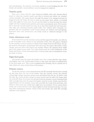
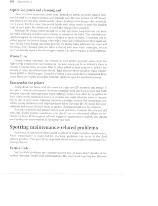
![§:azi'-i Q53 piTgggalzlcral. CJ[€(T!.w’,*Z’Zl?*"2iQ Cii-"T2.-C21 W2.-CZ»’Zl'7"’2.Z§6'i’2-Ct/7’tC6
the toner cartridge and rock it back and forljh to redistribiite cthe toner evenly in its
container. l?3...epil.ace the toner cartifi.clge a.n<:l EtCl_lLlS'l1 the print den.sity.
.i3'~_‘ll.C>l'.-llifil‘ cause of vei"tica[l fade is a dust- or debris»ifou.lecl transfer? corona. Un-
even chaige Cll.Sl1l§‘ll)lll=lOl'l will allow light streaks to foiin. Check the tran.sfer corona
and clean it with a ili.n.11i-;free swab dipped lightl.y in fresh isopropyl alcohol. After
clea.ning the wire, swab out any residue cv.dtil?i.1i_i.‘1. the corona case. be e.r;tit‘ei;i.i.ely care-
ful not to break the n'ionofila.men.t line wrapped around the corona. if the corona or
wrap is br*oken, the transfer corona. assem.bly will have to be replaced.
1i§irepo"iits
Dropouts generally appear as faded areas that are typically round in shape. The
most common source of dropouts is due to problems with the paper itself. Paper
with uneven moisture content or moist spots can result i.n dropouts. Even manufac-
turing defects in the paper can result in paper that produces dropout spots. Try
h, dry paper from a lclifferent source. it also is remotely possible that the transfer
corona is slightly di.i'ty. lf new paper fails to correct the problem, try cleaning the
tran.sfer corona as described earlier in this appe2i'iclTur.
"es*--:¢(‘D co
mm fzzaée 3 5”? Ci").. ~
Vertical lines appear one or more black streaks or smears directly f1;'om top to
bottom of the page. When vert:i.ca.l lines appear, it usiual.ly indicates that one or more
areas of the priinary corona wire are fouled with accumulations of dust or debris.
Clean. the ]_fJI‘.li'I1;3.i‘y corona as described €E1.i‘l.i.€fi' in this appendiii.
ll’ the dark vertica.l marks appear sn;iea.red, it is possible that tlie iusei' rollei;'
cleaning pad mi.gh.t be di.rty and need r'"epl.a.c:ement. if you do not ha.ve another clean-
ing pad on hand, you can gently clean the pad by removing it from the fus assem-
bly and gently brushing away any obvious cunnilaitionsof toner. A new cleaning
pad should be instal.led as soon as possible. lf new cieaiiiiiiig pad is available, replace
it according to the insti'uctions for the particular printer.
Fina.lly, it is possibl.e {hat the HP Cll['U.l1'Il has been scratched-—this problem is rare,
but can occur in printers serving heavy work load. l;ln.foi“tunately, the EP drum
would have to be replaced, but the drum is if.ypically part of the image formation en-
gine, wlgiiclfi. can easily be replaced. a.n entire module. Replzice the El? assembly and
try the printer agaii"i.
C-4»-
srainiiig
stain is typiically a dark horizontal patch ti at reoccurs to lesser degrees down
the page. Usually, the transport rollers that handle the paper are dirty. Clean the
ti*ansport rollers and transport feed guide as descr'ibed earlier in this appendix.
lt also is possible that the fuser roller cleaning pad might be dirty and need
replacement. lf you do not have anotl.ier clea.ning pad on hand, you can gently
clean the pad by removing it froin the. fuser assembly and gently brushing away
any obvious accumulations of toner. install a new cleanin.g pad as soon possi-
ble. lf a new cleaning pad is available, replace it according to the instructions for
the particular printer.
,......'P](https://image.slidesharecdn.com/ozgdplurrtdj8c4ktjrb-signature-f36449d24fae8f28749ba408629a60e09bfd643da03035012a2b233e7710df3e-poli-180806114914/85/Easy-laser-printer-maintenance-and-repair-187-320.jpg)
![i 82 Apgae’2*2.,d'zI;r: A
Repetiiive iieieeis
Repetitive detects occur at fi‘(i‘gLll£:1.ii' imieivals along the page. it is the spacing or
the defects along the page that can really cue you to the ELCl1il{:i.l. prohl.em. When the
defecits are spaced closely together (urider‘ 2 inches}, there is possibly a problem
vvith your paper transport roller(s). Oheck and clean each roller to remove all debris.
If the defects occur intervals oil? inches or greater, than there is defect on
either the development roller or the EP drum. Because both elements are incorpo-
iiated. into the image~i‘ormati.on engine (the EP cartridge), the entire assembly will
have to be replaced in either case. Try replacing the EP cartridge.
Eariiy termed eharaerers
Characters that are badly li'ormed general.ly appear vvavy or unstea<:ly. This proh-
lem is almost always caused by paper stock that is too sl.ici~: or sl.ippery-—-the rollers
have a dii'i‘icul.t time handling the paper. Try the printer again ivit.li sta.i.*iciar"cl 2()-
pound Xerography-grade paper. ll? the problem still. occurs on standard paper, the
printer scanner assembly is deitective and the printer vvill. require much more exteri-
sive bench repair.
aaweitigriserreiate prairie
A nuiuber of laser printei' probleiiiis are caused by oversights or errors in judg»
ment. This section of the appenclix shows you some oi the typical iiS€1‘~i‘€il£tl1tE§<fl prob-
lems found With. laser p1'lll.l1€if'S.
l. ll/0'21.’ ct/2"e Z'i"'C)'Z.Lbt€(Tt witlt_fi”equerzvt j'Cl/W2.-.5’. A laser piihiteii.‘ is onl;y as good as the
media that is used vvitli it. Paper, envelopes, and labels must be chosen
care;fully to erisuie proper pi"1ii"rtei' operatioii. Reiuembeii" that the printer‘
mechanics are designed to vvoi'l<. with media oi’ certain tlTllCl{lfl.€?SS€S, textures,
finishes, and Weights. l/ledia that is too heavy er f.l.llTi‘iE3§T or has an unusual or
chemically treated liiiiish might not be handl.ed properly by the printer
paper handling mechanism. Re;l’er to the printer 1§1'1¢*tII1l,l&1.l. to rind What is
allovvable, but staridard vvhite i/30-pouifrd bond xerogiaphy-grade paper
should always vvorl< properly. The easiest soljution here to try dill’er'eni;
types oi’ media.
l’o*rz.z.flr2'2,ict£ /2.r»mz,isucz.iMy Z,-2I-g/rziii or cZ,crr2"kir 'Zl"?"}"Z»CL§/eT.?.S'. Adjust the print density control
to achieve an optimum _print derisity. Casual user ‘ often forget that they
must adjust the print density wheel throughout tie life oi‘ the toner
cartridge. When new toner cartridge is installed; the print density must be
reduced or the resulting image might be too dark. As the toner is coiisumed,
print Will become lighter, so print density l'T1'l;i.S'l1 be increased. Very light print
might indicate that the toner cartridge must be replaced.
The ,]3'i""z'._"2z,t8'i" '7"‘t(fl'Z/-5' out Of??’Z€')’7"ZO'7"'@/. The memory in your printer serves as a
buffer for data being sent irom the host computer. For single-line printers.
the buffer need not be very large. For laser printers, hovvever, there must be
enough memory to hold complex, high-resolution images (usually about i or
2l/lB). The entire image must be loaded into the laser pri:o.ter _l3Ll.l“l'€i‘ before
2.
*”“"'"I/‘
1](https://image.slidesharecdn.com/ozgdplurrtdj8c4ktjrb-signature-f36449d24fae8f28749ba408629a60e09bfd643da03035012a2b233e7710df3e-poli-180806114914/85/Easy-laser-printer-maintenance-and-repair-188-320.jpg)


![.%t(§C‘!
8
9
10
ll
l2
l-3
ill
l6
*“‘q; we
aha ~
r-1*/4.;ef / tat t-..ti D
c. Checlr/replace the l.E.l.S€IiI‘/scanner einblJ__v
d. Oheclr all connectors and wiring fIl"‘OlTljl the scaniier
Pi‘jl.l.l'l} just sligi"1tly llEl.l.l.'lil.
-(jlliecjlii/'adiust the coiit.ra.st CiOllliIj'Ol setting
b. Qll€Cil.( paper qua.lity
c. Oheclq toiier i€V€.l/l“€plEl.C'.€ the EP C£Z:l..lI’lll‘l(lg€‘
d. cll€C'1i{/§l'€pl£1C€ the di*um seinsitivi.ty sensor switclies
e. Checl</'cl.ean/replace the transfer corona assembly
ii Clciech or replace the high~yoltage power supply
Priiui. lias rougli or suede appea.rai1§ice.
a. Replace the E-OP
Print appears Sll.l.€2l.fi'€<Cl or ;§used improperly.
a. Oh.ecl</'i‘epla.ce i"'usin.g roller cleaning pad (s)
b. Clean/irepla.ce the i’usi;ng assembly
c. Checl<:/‘replace the sttatic discharge comb
d. Oheck the drive train
e. Oheclr and clear Ol;'Sl1l.‘l.lCil1lons in the paper path
Printed inia.ges a;i;>pear to be distorted.
a. Oliecli the paper path ancl mech.a.n.i.cal assemblies
b. Oheck or Il‘€l_)l&?i.C<3 the scanning assemblyt
Print shows regular or repetitiivte defects.
a. inch deii‘e<::ts-~checl< or replace the T11‘-P cartridge
b ._ ' ich cl.ei'ec:t'is~m--c:l.iecl< or replace the EP cartridge
c 60 inch de;i’ect.s--check or replace the liiisirig .rol.lers
d. iiiheclr raid all otl.iei' rollers or belts
The page a.ppe'ars <:oi.irplet.ely blacl< eXce]3't .'l'OlI'l“lOl‘lZO1‘ltEtl white stripes
a. OheCit;/i"€pil£1.C€ the l'ibei.*op'i;ic beam c.ieitector cable
b. Chec§</replace the laser‘/scanniiig assemliily
Th nage appears skewed.
l'"l.€C:i the priper tray
b. CJifiec:I.< the paper
c. Onecit/rejpjlace the p piclcup assen.ibly
d. Checl<:/replace the registrattion. assembly
e. Olieclc./cllea.i' airy obsti;"uctions
The image l ed in;i}_;>roperly.
a. Oheck the paper tlray tabs
b. Checilr/‘replace the paper ti'ay switches
c. Replace the l5lC[P
There V€?l”l‘.-lCit1l black in the iinage.
C/D.QZ> r-g
FD
CDH_
1*;
U} VC/3,_.-. N
Oheclr/clean. the priiii.a.i‘y corona.
b. Replace the EP cartridge
Replace the L113‘ C3to
.
er§%?“ fee A
kn,“
aniifit ewe
5
-
ll. You iiiid a PAl?’l?.R. OUT message.
Oheck the paper supply](https://image.slidesharecdn.com/ozgdplurrtdj8c4ktjrb-signature-f36449d24fae8f28749ba408629a60e09bfd643da03035012a2b233e7710df3e-poli-180806114914/85/Easy-laser-printer-maintenance-and-repair-194-320.jpg)
![C’ompref2.ev'2.s'i'0e t'1’*oubZ.es/2.ootvLi'z,g gwjdes la‘)
b. Clieck the paper tray and tray lD sensors
c. Oheck the papei;'~out flag and sensor
d. Replace the EOP
2. You see a PAPER JAl/l message.
a. Oheck the paper supply quantity and quality
b. Oheck/clear any obstructions in the paper path
c. Olieck/i.‘epla.ce the main motor
d. Ohec].</clear any obstructions in the gear train
e. Ol.'ieck/i'ejpla.ce the paper pickup assembly
f. Olieck/replace the registration/transfer assembly
g. Oheck/replace the fusing/exit assembly
The printed image appears with a smudged band and overprint.
Ol'ieck/replace the paper pickup assembly
b. Oheck/clear any obstructions in the paper path
tlhapter R: Re" er a irerinrir i. s
l. You see a PAPER OUT message even though paper is available.
Oheck/replace the paper sensor mechanical ilag
b. Oheck/replr¢.. -. . fine paper sensor switch or optoisolator
c. Replace the 3
l7‘using tempera;Lure control is ineffective. Temperature never climbs, or
climbs out of control. This might affect print quality or initialization for EP
printers.
a. Oheck/re§_Jlace the sensor thermistor‘
b. Oh.eck/replace the thermoprotector
c. Replace the ECP
8. You see a .PRlilTER OPEN message.
Oheck that all printer housings are securely closed
b. Oheck all housing sensor switches and actuators
c. Oheck power to each housing sensor
d. Replace the EOP
an ' {sf] ;,;41SvrQ‘.'" r;.az=a> -..‘.
E
-'.':eiéJ$= ='s;,-;(>"' =.f:J?]‘5.(L'E-. ;*;a';.;=;ai.*.
...J
,...c*"3
cumF?»
ewe
nt:ea
@@
‘ - - e
" it Rranner trjainstar
prehie
l. You see a general SO.r.NllEl¥€. ERROR message.
Oheck all conneciiors arid wiring between the laser/scanner assembly and
EOP
b. Oheck/replace the laser/scanner assembly
c. Replace the EOP
2. The main motor does not turn, or turns internuttently.
a. Oheck all connectors and wiring between the main motor and ECP
b. Oheck/clear any obstructions in the paper path
c. Oheck/replace the. dc power supply
d. Replace the main motor
e. Replace the ECJP](https://image.slidesharecdn.com/ozgdplurrtdj8c4ktjrb-signature-f36449d24fae8f28749ba408629a60e09bfd643da03035012a2b233e7710df3e-poli-180806114914/85/Easy-laser-printer-maintenance-and-repair-195-320.jpg)

![w ©WCO7’l"Z.]3?"(3}'2.-67-’Z:S7l'lJ€ ti**o2.tblesltoot/mg guides
2. One or more keys is interriuttent or defective. Excessive force or multiple
attempts might be needed to operate the key(s). Printer appears to operate
normally othei'wise.
a. Oheck/replace all questionable keys
lb. Replace the control panel assembly
One or more indicators fail to function, or the LOD alphanumeric display
appears erratic. Printer appears to operate normally otherwise.
a. Oheck all connectors and interconnecting Wiring
b. Oheck control panel supply voltage (s)
c. Replace the control panel assembly
d. Replace the EOP
‘Q @
'é ‘L. .9 9. “F
l. Printer does not initialize from a cold-start turn-on. There is no visible
act;'.vi.ty in the printer after povver is turned on, but povver indicators are lit.
Seliitesrt does not Work.
a. Oheck/replace the dc povver supply
b. Oheck/replace the system clock
c. R.eplace pi.'inter RAl/l chips to check for defective memory
d. Replace printer ASIO or slave microprocessor
e. Replace printerprogram ROl/l
gl’. Replace the EOP
Printer operation freezes or becomes highly erratic during operation. You
must activate the printer lroin. a cold—start to restore operation. Self-test
might work until the printer freezes.
a. Oheck/replace the dc power supply
b. Replace printer pi;'ogra.m ROM
c. Replace the printer main microprocessor
d. Oheck for‘ therinal intermittents
e. Replace the EOP
9L.-1.](https://image.slidesharecdn.com/ozgdplurrtdj8c4ktjrb-signature-f36449d24fae8f28749ba408629a60e09bfd643da03035012a2b233e7710df3e-poli-180806114914/85/Easy-laser-printer-maintenance-and-repair-197-320.jpg)

![Mici‘oMedics (complete piiiiter parts
and repair services)
6625 W. Jarvis
Niles, 1L 6071.4
Tel: 800-678-5800
Tel: 708-647-1010
Mouser Electronics (general. parts only)
2401 Highway 287 N.
Mansfield, TX 76068-4
Tel: 800-846-6878
Tel: 817-488-4422
Farr: 817-488-0981
Natiional Parts Depot, inc. (printer parts
ooto -1
and technical manuals)
81 Elkay Dr.
Chester, NY 10918
Tel: 914-469-4800
Fax: 914-469-4855
Northstar (printer parts and service)
7940 Ranchers Rd.
lvliiuieapolis, l/lN 55-.
Tel: 800-969-0009
Farr: 612-785-1185
*1-Fron1:0
ProAmer'ica (printei' parts)
650 lntei*national Pkwy.
Suite 180
Richardson, 75081
Tel: 800-888-9600
Tel: 214-680-9600
Fax: 214-690-8648
eerai£270,-.
V(3’i"‘Z.dO'1"S 198
Robec Spare Parts (printer parts and
technica.l manuals)
425 Privet Rd.
11oi.'shar‘rfi, PA l 9044
Tel: 800-228-7078
Tel; 215-675-9800
Farr: 215-672-5605
The Printer Works (_printei' parts, service,
supplies, accessories, and service)
84-81 Arden. Rd.
l.—laywa.rd, CA 94545
Tel: 800-285-61. 16
Tel: 510-887-61.16
P‘aX: 510-786-0589
U1'l.i.CC)1l.lp, inc. (printer part.s and repairs)
2400 W. F1111-11 St.
Santa Ana, CA 9270
Tel: 800-859-509.2
Tel: 714-571-1900
i7‘a.X: 7Il.4-571-1909
O3
. . g, _ _ _ _._...,,, ., _ i; . .
B-+~K Precision (a division of l/.l.El..X1T.€C [Proifessi.onal. BBS subscriptions and
111ij.er‘ngitio1ial) T/*2.-6 PC TOOti’30;1:1? iiewsletter $89
6470 W. Cortland St. per year US. See order form in the back
Chicago, 1L 60685 of the book]
T@11 312-889-1448 .l%?lovva.i'd w. Sams Co.
F353 313‘794"974O 2647 Waterfront Parkway East Dr.
Dynamic Learning Systems lndianapoiis, 1N 46214--2041.
Attn: Stephen J. Bigelow Tel: 800-428-7267
P.O. Box 805
Marlboro, MA 01.
TechNet BBS: 50 -O0
"Q1UK
C/3[IO C71 CT --1 CO (N/8/1)](https://image.slidesharecdn.com/ozgdplurrtdj8c4ktjrb-signature-f36449d24fae8f28749ba408629a60e09bfd643da03035012a2b233e7710df3e-poli-180806114914/85/Easy-laser-printer-maintenance-and-repair-199-320.jpg)


![Gliosscmly W7
EFT (eliei"eetei*s per iiieieh.) The ntini"il:>ei* of Cill.‘<1I‘%1.ClI-€1'SlLllEl,l}VVll.lfll] onto one inch of
Ilflorizontajl. line space, also celled cli.ai;'actei' pitch.
Qiyll (eentiefi piroeessing unit) The inisjoif conti;'olling logic element in your
p1'intei?’s ciyrcuitry.
(eieeiv to send} S€E?l‘lE1..lllEl.TllClSll&1lil1lg line at the C()l'l'll_)LllT.€l‘ usually connected
to the R'Il.“S line of p1.'intei'.
date Any of —" ‘ht 13E:-1,‘l)E-A‘1~‘§l»]-Q/tl (late lines ii.lnit ceiiy l3ll'1'c'.llf‘}7 l1l_fC)I‘l.'ll.ELtl_Oll. fifoin coinputer to
l)li‘l.llll€‘l‘.
date liiifiei‘ T‘e1n1;:>oi‘e.i*y lneinoiiy Where Cll‘¢l.l§"21CJE@l"SffI'O1"l"l.l}h€ computeif are stored by
the pifinteif l3l‘lOi‘ to })l'lllfl1ll'lg.
(Bets iQ)%1Ll“§?i@§° llEe:*%;e@::"t) A S@lI‘l‘<1l h‘<".llil.ClSll‘<1l{lllg line llSLl<’;Ll.lyifOl1l1Cl in S€li'il&1l1l1C>-
dein i,11l;ei"faces.
dew/elepilng The inoveinent <:>iftoi1e1ffroin %3tl10ll€l§‘ supply to the l&l1€lll1 ii‘nage Written
to the chergecl clrunil Sll_ill.‘1l?di(Z€.
diode A l1WO-t@iI'jl1l;l1lt1l electiionie device used to conduct current in one Cll.l"€Cl1l.Oll
only. '
si (dots per inehfl A laseil" pi'intei*’s i‘esolutiion expressed as the number oil’ indi-
vidualjly ElCl.Cll‘€SS‘cll')l@ dots that can he pleeecl in both the ll.OlY'l.ZOll.U;ll and V@lt'JElCiE§ll.
direetions.
C3 >--»UO
Qt:F’X='4
di"iyei“ An einpliliei‘ used to conveift l_oIv-power sign.alls into l'l_l.gll—pOVV€‘I' signajls.
(Eli?site Set hleedgr} The p.‘£‘l_l'l.l.El.l'Y con1jputei;' sigiiel line 1i?Ol‘ll&Ell'(Il‘VV2?t1‘€ hzuidshale
ing over seiiiel inte1;*ifaee. it connected to the D’.l‘l€i line at the piintei".
UTE (Theta ‘Tezsininel Iliieetdyl The pl‘l.1ll.El-l'y sei'is.lp1i*intei1' sigimlforl1a1‘<ilvva.i‘e he.nd~
SllEll<lilg over at S€[.l'l.3.-1. iiiiilieilece. lt is confinected to the DSR pin at the C<3l.llpLll1€l‘.
(electeoiiiic eonmfol A genei'ic t€l"ll1l.1‘€f€l"l1"illg to the elecztroniic as-
seinbly used to COIl_l]l‘Ol. at laser priiitei*. The ECP consists oil’ Dl&l.1il logic, n;1enio11'y,
di'ivei's, and -at control _lQE~l.l'l€l. Also c:slil.ecl at covllzizirolite/2*‘.
einittei' One of thiee €l.€CilI.I‘OCl€S on il:>ipolei1' il1I"<‘Zl.IlSlST-OI‘.
(eleeti*opi"iote>gi*e.pliic) Also celled (;?Zi6’-C?ZZ’l"‘C)SZJCIlI?’:»C' (see ll‘ S).Lu
EPT~'?;®ll/ll ifeisesehie pi“egi=e.miiiellile i“eed»=only ineinosy) An advanced type of
]Q€1j"lll£;l1'l€?;'lli, ineinoi“y 'Cl18,l'.1 (zen he ei';2ised and i‘e~Wi‘iit*ten to i_1<1.Cj1f:il>1.‘37i2.i.l,_E.1.6‘§E;I
ES (*Bllt3i(f'§?Ziii“%3#S'%C33éf%Ci@Cil procress Ofll'C1"€El,lf,flilgll‘{lE1.g(-ZS using the ili'oi'ces of l1igl'1l~volli.age to
El.U1I"E£ClI or repel l.'ll€(Ill8. (tonei') as needed to forin the desired ii1i.2ige.
esiposuife The process of cliscl”iai;‘ging; the d.i'uin after" Cl.€é1-Ili.l'l.g to l"€Ilfl1OV(i? any elec-
lL.=I‘lCEll charges on the Cl7{‘U.il"l. ipyhotiosensitive smfece.
‘tixiiig See t"*ueing.
font A C1’l€LIl’EEiCll€l‘ set Of1;)%EL1"i':Ij,{:i1_]_1Z?i.-jg.‘ size, style, and acing.
font seeliiig»; The _p1i'oce “ of piioc‘li.icing' bi.t1."naps of y2u'ioiis sizes iljlfoin a gen.eific
source oi’ size-independent Cilil8;l1‘8tC'lIE‘l' l1lfOl'f'1Tl§‘lF3illlO3.1.
tusiiig The piioeess oi’ i1.sing; lieet €;l.l'lCl pifessuife to bond toner to porous 1;>apei" sur-
ifece.
gates illllI(€:gl'Ei,.lf.€C'l (_“§lll‘Cl,llT-S used to jpei'l*oi'in siifnple logical O]3€li"E.l.'CltOllS on loinzufy Cldllél
in digital systems.
{gse‘tiiid.) A coininon €l€Cl'-lf‘lC£;l_l l‘€f€l‘€llCi@ point for €%l€C{tl'Ol1lC clam signals.
t{%i1°T% *<(e;enes*elwptii"poee in'tei"."t“ece hue) A pz3u‘a.ljliel coi'"nn'iu.nication lll.'l1€Il‘fELC€ in-
tended l)l‘llll'£1li_‘Ill.y for ll€l1W'Ol‘l<i€Cl insti:‘i;iniei‘itatiorl, also known as lEllE 488.
cc»T3
U2 U](https://image.slidesharecdn.com/ozgdplurrtdj8c4ktjrb-signature-f36449d24fae8f28749ba408629a60e09bfd643da03035012a2b233e7710df3e-poli-180806114914/85/Easy-laser-printer-maintenance-and-repair-203-320.jpg)
![i ‘J8 LfL()S.$(..l.;)
gray scaie series oi’ shades ru.nning from white to black. For laser printers,
shades are pii‘OCltlC€i‘.Cl by creating vai'ious patterns of dots (called (lit/?,8?"’£7'Zg).
inductance The jil.'l€EtSLlif'€ of the ability oi’ a device to store a magnetic charge, mea-
sured. in henrys, milliiheni'ys, or mici'ohenrys.
inductor device used to store magnetic cliarge.
initiaiisation Restoring cleiai.il.‘li. or start-up conditions to the printer due to fault or
pOW€l'—l.l]).
iandscape The orientatioii of characters or images on page that runs the short
Way (on an 8.5 >< ll inch page, the 8.5 inch sides would be vertical).
iaser device producing‘ a narrovv intense beam of coherent, single-wavelength
light Waves.
iiilfi (iiipiid crystai dispiay) A display using character images formed from lay-
ers of voltage-polarized liquid. in its off state, the liquid is clear. In its on state,
the liquid is opaqiie.
LED (tight-emitting diode) semiconductor device designed such that photons
of light are liberated when its p-n junction is i’orvv'ard biased.
lpi (tines per inch) The number oi hori;zonta.l lines that fit into one inch of verti-
cal page space, also known line pitch.
liw (ii/iegaiiyte) An amount oi’ memory or storage area. Each megabyte is 1,048
bytes.
inicroprocessor A complex progi."anunable logic device that Will perform vari-
ous logical operations and cal.cul.ations based on predetermined program in-
structions.
motor An electromechanical device used to convert electrical energy into mechan-
ical motion. There are several types ol’ motors used in laser printers.
MTEEF (inean tirne between iaiiures) A measure of a devices reliability ex-
pressed as time or an amount oi’ use.
inultiineter A versatile test instruinent used to test such circuit parameters as volt-
age, curreiit, and resistance. Also called a DVM or VOM.
parity An e;x:tra bit aclded to serial data Word used to check for errors in coin-
inunicatioii.
pavvi Curved plastic assemblies resembling claws that guide charged paper through
the printer.
Pfiii (printer corninand iangu:-age) A popular printer control language developed
by HeWl.ett-Pacl<ard that is used or emulated by almost all S00 >< 300 dpi resolu-
tion laser printers.
Piiii (page-description language) A resolution»-independent printer language
that describes the elements oi‘ a printed page. Commonly used With PostScript
or PostScript-compatible pr.i.nters.
PE (Paper Error) A handshaking signal sent i’rom the printer to tell the computer
that paper is €X..l.l€l.LlSlI€Cl.
photosensitive A mateifi.al or device that reacts electrically when exposed to light.
pieaoeiectric The property of certain materials to vibrate when voltage is applied
to them.
“Cr: -4CD](https://image.slidesharecdn.com/ozgdplurrtdj8c4ktjrb-signature-f36449d24fae8f28749ba408629a60e09bfd643da03035012a2b233e7710df3e-poli-180806114914/85/Easy-laser-printer-maintenance-and-repair-204-320.jpg)
![Glosso.xi";y iii‘)
portrait The orientatfioin of characters or images on a page that r*uns the long Way
(on an 8.5 >< ll inch page, the ll inch sides would run vertical).
ppm (pages per rninnte) The ma.ximum speed at vvhich laser printer engine can
move paper.
itéili/i (random-access ineinory) A temporary memory device used to store digi-
tal ll'lfOl‘i1l€t.l;l.Oiji..
regniator An electronic device used to control the output of voltage and current
from a povver supply.
resistance The measure of a devices ability to limit electrical current, measured in
ohms, ldloluns, or megohins.
resistor A device used to limit the iilovv of el.ectrical current.
ERET (resointion enhancement tecitnoiogy) introduced by l-leivlett-Paclrard for
the LaserJet lil, BET improves edge definition by varying the size oi? dots around
the edges of bitmaps.
it®lti tread-oniy inernory) A permanent memory device used to store digital in-
iormation.
RT8 (iteotiest To Send) A printer serial ha.iiclslial<iiig line usually connected to
the GT8 line oi‘ a computer.
itx (Receive iiata) This is the serial input line. The printer‘ Rx line is connected to
the computer Tx line.
scanner in laser printers, the scanner assembly uses a rotating hexagonal mirror to
direct the Writing laser beam along the photosensitive d.run'i surface. Dots are
formed by turning the laser beam. on or off While the beam is being scanned.
ect A control signal from the computer that prepares the printer to receive data.
separation pad A soit rubber pad in the paper transfer assembly that prevents
more than one page at time from entering the printer.
sort tent Foiit vector or lZ)ll1l'i'iE1.],;) data on diskette or other computer media (such as
CD-ROM).
soienoid An electromechanical. device consisting oi coil of Wire Wrapped a.i'ound
a core which is free to move.
oioe A handslia.l<ing line from the computer tlfiat tells the pl.“.i.ill1(-311‘ to accept valid
parallel data on its data lines.
thermistor A temperature S€~3ij'l.Siiig device used to regulate ten;iperatiire in the fus-
ing roller assembly.
toner A fine powder of plastic, iron, and pigments u ed to if'orm images in electro-
static printing systems.
transter The process oi‘ attracting the developed image off the drum and onto the
charged paper suri’ace.
transistor A three-teriininal electronic device vvhose output signal is proportional
to its input signal. A transistor can act as an amplijtier or a svvitch.
transtoriner A device used to step the voltage and Citllf‘fl'€lllL levels of ac signals.
(Lil) (Tism
Q52 c’=i~mi
C/1'
Tx (iransinit Data) This is the data output line for serial devices. The computer
Tx line is connected to the printer Rx line.](https://image.slidesharecdn.com/ozgdplurrtdj8c4ktjrb-signature-f36449d24fae8f28749ba408629a60e09bfd643da03035012a2b233e7710df3e-poli-180806114914/85/Easy-laser-printer-maintenance-and-repair-205-320.jpg)

This document provides an overview of laser printer technology. It discusses the electrophotographic printing process, describing the key components and systems involved like the charging, writing, developing, transfer, and fusing stages. It also covers troubleshooting techniques for addressing common issues in laser printers. Specific topics covered include mechanical systems, power supplies, image formation, electronic control packages, and safety procedures.