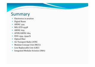
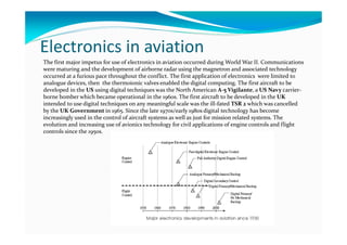
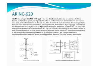
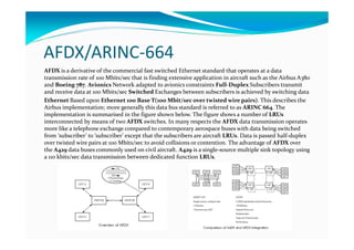
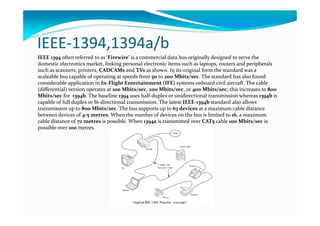
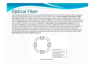
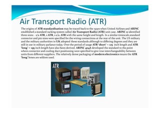
Massimo Talia
Electronic Engineer
Web address: http://www.taliawebs.com
Summary
Electronics in aviation
Digital Buses
ARINC-429
MIL-STD-1553B
ARINC-629
AFDX/ARINC-664
IEEE-1394, 1394a/b
Optical fiber
Air Transport Radio (ATR)
Modular Concept Unit (MCU)
Line Replaceable Unit (LRU)
Integrated Modular Avionics (IMA)
Electronics in aviation
The first major impetus for use of electronics in aviation occurred during World War II. Communications
were maturing and the development of airborne radar using the magnetron and associated technology
occurred at a furious pace throughout the conflict. The first application of electronics were limited to
analogue devices, then the thermoionic valves enabled the digital computing. The first aircraft to be
developed in the US using digital techniques was the North American A-5 Vigilante, a US Navy carrier-
borne bomber which became operational in the 1960s. The first aircraft to be developed in the UK
intended to use digital techniques on any meaningful scale was the ill-fated TSR 2 which was cancelled
by the UK Government in 1965. Since the late 1970s/early 1980s digital technology has become
increasingly used in the control of aircraft systems as well as just for mission related systems. The
evolution and increasing use of avionics technology for civil applications of engine controls and flight
controls since the 1950s.
Digital Buses-1
The advent of standard digital data buses began in 1974 with the specification by the US Air Force of
MIL-STD-1553. The ARINC 429 data bus became the first standard data bus to be specified and widely
used for civil aircraft being widely used on the Boeing 757 and 767 and Airbus A300/A310 in the late
1970s and early 1980s. ARINC 429 (A429) is widely used on a range of civil aircraft today as will become
apparent during this chapter. In the early 1980s Boeing developed a more capable digital data bus termed
Digital Autonomous Terminal Access Communication (DATAC) which later became an ARINC
standard as A629; the Boeing 777 is the first and at present the only aircraft to use this more capable
data bus. Digital data transmission techniques use links which send streams of digital data between
equipment. These data links comprise only two or four twisted wires and therefore the interconnecting
wiring is greatly reduced. Common types of digital data transmission are:
Single Source–Single Sink: this is the earliest application and comprises a dedicated link from one
equipment to another. This was developed in the 1970s for use on Tornado and Sea Harrier avionics
systems. This technique is not used for the integration of aircraft systems;
Single Source–Multiple Sink: this describes a technique where one transmitting equipment can
send data to a number of recipient equipment (sinks). ARINC 429 is an example of this data bus
which is widely used by civil transports and business jets;
Multiple Source –Multiple Sink: in this system multiple transmitting sources may transmit data to
multiple receivers. This is known as a full-duplex system and is widely employed by military users
(MIL-STD-1553B) and by the B777 (ARINC 629).
Digital Buses-2
The use of digital data buses to integrated aircraft systems has increased enormously over the last few
years. A huge impetus has resulted from the introduction of Commercial-off-the-Shelf (COTS)
technology – adopting those buses that have been designed for the computer and telecommunications
industries. This technology has been adopted for reasons of cost, speed, component obsolesence and
availability though care must be exercised to ensure that deterministic variants are selected for
aerospace applications. The figure below shows the main digital bus for the aerospace market. The most
common used introduced for large-scale aircraft systems integration are: ARINC 429, MIL-STD-1553B,
ARINC 629, AFDX/ARINC 664, IEEE 1394b .
ARINC-429
The characteristics of ARINC 429 were agreed among the airlines in 1977/78 and the data bus first used on
the B757/B767 and Airbus A300 and A310 aircraft. ARINC, short for Aeronautical Radio Inc. is a
corporation in the US whose stakeholders comprise US and foreign airlines, and aircraft manufacturers.
The ARINC 429 (A429) bus operates in a single-source-multiple sink mode which is a source that may
transmit to a number of different terminals or sinks, each of which may receive the data message.
MIL-STD-1553B has evolved since the original publication of MIL-STD-1553 in 1973. The standard has
developed through 1553A standard issued in 1975 to the present 1553B standard issued in September 1978.
The data bus comprises a twin twisted wire pair along which DATA and DATA complement are passed.
The standard generally allows for dual-redundant operation. Data is transmitted at 1 MHz using a self-
clocked Manchester bi-phase digital format. Control of the bus is executed by a Bus Controller (BC)
which isto a number of Remote Terminals (RTs) (up to a maximum of 31) via the data bus. RTs may be
processors in their own right or may interface a number of subsystems (up to a maximum of 30) with the
data bus. Data is transmitted at 1 MHz using a self-clocked Manchester bi-phase digital format.
MIL-STD-1553B
ARINC-629
ARINC 629 (A629) – like MIL-STD-1553B – is a true data bus in that the bus operates as a Multiple-
Source, Multiple Sink system, see figure below. That is, each terminal can transmit data to, and receive
data from, every other terminal on the data bus. This allows much more freedom in the exchange of data
between units in the avionics system than the Single-Source, Multiple Sink A429 topology. Furthermore
the data rates are much higher than for A429 where the highest data rate is 100 kbits/sec. The A629 data
bus operates at 2Mbits/sec or 20 times that of A429. The true data bus topology is much more flexible in
that additional units can be fairly readily accepted physically on the data bus. A further attractive feature
is the ability to accommodate up to a total of 131 terminals on a data bus, though in a realistic
implementation data bus traffic would probably preclude the use of this large number of terminals.
AFDX/ARINC-664
AFDX is a derivative of the commercial fast switched Ethernet standard that operates at a data
transmission rate of 100 Mbits/sec that is finding extensive application in aircraft such as the Airbus A380
and Boeing 787. Avionics Network adapted to avionics constraints Full-Duplex Subscribers transmit
and receive data at 100 Mbits/sec Switched Exchanges between subscribers is achieved by switching data
Ethernet Based upon Ethernet 100 Base T(100 Mbit/sec over twisted wire pairs). This describes the
Airbus implementation; more generally this data bus standard is referred to as ARINC 664. The
implementation is summarised in the figure shown below. The figure shows a number of LRUs
interconnected by means of two AFDX switches. In many respects the AFDX data transmission operates
more like a telephone exchange compared to contemporary aerospace buses with data being switched
from ‘subscriber’ to ‘subscriber’ except that the subscribers are aircraft LRUs. Data is passed half-duplex
over twisted wire pairs at 100 Mbits/sec to avoid collisions or contention. The advantage of AFDX over
the A429 data buses commonly used on civil aircraft. A429 is a single-source multiple sink topology using
a 110 kbits/sec data transmission between dedicated function LRUs.
IEEE-1394,1394a/b
IEEE 1394 often referred to as ‘Firewire’ is a commercial data bus originally designed to serve the
domestic electronics market, linking personal electronic items such as laptops, routers and peripherals
such as scanners, printers, CADCAMs and TVs as shown. In its original form the standard was a
scaleable bus capable of operating at speeds from 50 to 200 Mbits/sec. The standard has also found
considerable application in In-Flight Entertainment (IFE) systems onboard civil aircraft. The cable
(differential) version operates at 100 Mbits/sec, 200 Mbits/sec, or 400 Mbits/sec; this increases to 800
Mbits/sec for 1394b. The baseline 1394 uses half-duplex or unidirectional transmission whereas 1394b is
capable of full duplex or bi-directional transmission. The latest IEEE-1394b standard also allows
transmission up to 800 Mbits/sec. The bus supports up to 63 devices at a maximum cable distance
between devices of 4-5 metres. When the number of devices on the bus is limited to 16, a maximum
cable distance of 72 metres is possible. When 1394a is transmitted over CAT5 cable 100 Mbits/sec is
possible over 100 metres.
Optical FiberThe examples described thus far relate to electrically signalled data buses. Fibre-optic interconnections offer an alternative
to the electrically signalled bus that is much faster and more robust in terms of Electro-Magnetic Interference (EMI).
Fibre-optic techniques are widely used in the telecommunications industry and those used in cable networks serving
domestic applications may typically operate at around 50–100 MHz. A major problem with fibre-optic communication is
that it is uni-directional. That is the signal may only pass in one direction and if bi-directional communication is required
then two fibres are needed. There is also no ‘T-junction’ in fibre-optics and communication networks have to be
formed by ‘Y-junctions’or ring topologies. the data rate is a modest 1.25 Mbits/sec which is no real improvement over
conventional buses such as MIL-STD-1553B and indeed is slower than A629. A fibre-optic bus does have the capability of
operating at much higher data rates. It appears that the data rate in this case may have been limited by the protocol
(control philosophy) which is an adaptation of a US PC/Industrial Local Area Network (LAN) protocol widely used in the
US. Fibre-optic standards have been agreed and utilised on a small scale within the avionics community, usually for On-
Board Maintenance System (OMS) applications.
Air Transport Radio (ATR)
The origins of ATR standardisation may be traced back to the 1930s when United Airlines and ARINC
established a standard racking system called Air Transport Radio (ATR) unit case. ARINC 11 identified
three sizes: . 1/2 ATR, 1 ATR, 1 1/2. ATR with the same height and length. In a similar timescale,standard
connector and pin sizes were specified for the wiring connections at the rear of the unit. The US military
and the military authorities in UK adopted these standards although to differing degrees and they are
still in use in military parlance today. Over the period of usage ATR ‘short’ ∼ 125 inch length and ATR
‘long’ ∼ 195 inch length have also been derived. ARINC 404A developed the standard to the point
where connector and cooling duct positioning were specified to give true interchangeability between
units from different suppliers. The relatively dense packaging of modern electronics means the ATR
‘long’ boxes are seldom used.
Modular Concept Unit (MCU)
The civil airline community developed the standardisation argument further which was to develop the
Modular concept Unit (MCU). An 8 MCU box is virtually equivalent to 1 ATR and boxes are sized in
MCU units. A typical small aircraft systems control unit today might be 2 MCU while a larger avionics
unit such as an Air Data and Inertial Reference System (ADIRS) combining the Inertial Reference
System (IRS) with the air data computer function may be 8 or 10 MCU; 1 MCU is roughly equivalent to
∼ 1. inch but the true method of sizing an MCU unit is given in Figure below. An 8 MCU box will
therefore be 7.64 in high x 12.76 in deep x 10.37 in wide. The adoption of this concept was in conjunction
with ARINC 600 which specifies connectors, cooling air inlets etc in the same way that ARINC 404A did
earlier.
Line Replaceable Unit (LRU)
The architecture of a typical avionics Line Replaceable Unit (LRU) is shown in figure below. This shows the usual
interfaces and component elements. The unit is powered by a Power Supply Unit (PSU) which converts either 115V AC or
28V DC aircraft electrical power to low voltage DC levels − +5V and + or −15V are typical – for the predominant
microelectronic devices. In some cases where commercially driven technology is used +33V may also be required. The
processor/memory module communicates with the various I/O modules via the processor bus. The ‘real world’ to the left
of the LRU interfaces with the processor bus via a variety of I/O devices which convert true analogue va The right portion
of the LRU interfaces with other LRUs by means of digital data buses; in this example A429 is shown and it is certainly the
most common data bus in use in civil avionics systems today. One of the shortcomings exhibited by microelectronics is
their susceptibility to external voltage surges and static electricity. Extreme care must be taken when handling the devices
outside the LRU as the release of static electricity can irrevocably damage the devices. The environment that the modern
avionics LRU has to withstand and be tested to withstand is onerous as will be seen later. The environmental and EMI
(Electro-Magnetic Interference) challenges faced by the LRU in the aircraft can be quite severe and include:
• Electro-Magnetic Interference
• Radio and radar stations and communications
• Physical effects due to one or more of the following: vibration, temperature,altitude, dust,sand.
Integrated Modular Avionics (IMA)
Integrated Modular Avionics (IMA) is a new packaging technique which could move electronic
packaging beyond the ARINC 600 era. ARINC 600 as described earlier relates to the specification of in
recent transport aircraft LRUs and this is the packaging technique used by many aircraft flying today.
However the move towards a more integrated solution is being sought as the avionics technology
increasingly becomes smaller and the benefits to be attained by greater integration become very
attractive. Therefore the advent of Integrated Modular Avionics introduces an integrated cabinet
approach where the conventional ARINC 600 LRUs are replaced by fewer units. The diagram below
depicts how the functionality of seven ARINC 600 LRUs (LRUs A through to J) may instead be installed
in an integrated rack or cabinet as seven Line Replaceable Modules (LRMs) (LRMs A through to J).

Avionic systems: onboard electronics

  • 1.
    Massimo Talia Electronic Engineer Webaddress: http://www.taliawebs.com
  • 2.
    Summary Electronics in aviation DigitalBuses ARINC-429 MIL-STD-1553B ARINC-629 AFDX/ARINC-664 IEEE-1394, 1394a/b Optical fiber Air Transport Radio (ATR) Modular Concept Unit (MCU) Line Replaceable Unit (LRU) Integrated Modular Avionics (IMA)
  • 3.
    Electronics in aviation Thefirst major impetus for use of electronics in aviation occurred during World War II. Communications were maturing and the development of airborne radar using the magnetron and associated technology occurred at a furious pace throughout the conflict. The first application of electronics were limited to analogue devices, then the thermoionic valves enabled the digital computing. The first aircraft to be developed in the US using digital techniques was the North American A-5 Vigilante, a US Navy carrier- borne bomber which became operational in the 1960s. The first aircraft to be developed in the UK intended to use digital techniques on any meaningful scale was the ill-fated TSR 2 which was cancelled by the UK Government in 1965. Since the late 1970s/early 1980s digital technology has become increasingly used in the control of aircraft systems as well as just for mission related systems. The evolution and increasing use of avionics technology for civil applications of engine controls and flight controls since the 1950s.
  • 4.
    Digital Buses-1 The adventof standard digital data buses began in 1974 with the specification by the US Air Force of MIL-STD-1553. The ARINC 429 data bus became the first standard data bus to be specified and widely used for civil aircraft being widely used on the Boeing 757 and 767 and Airbus A300/A310 in the late 1970s and early 1980s. ARINC 429 (A429) is widely used on a range of civil aircraft today as will become apparent during this chapter. In the early 1980s Boeing developed a more capable digital data bus termed Digital Autonomous Terminal Access Communication (DATAC) which later became an ARINC standard as A629; the Boeing 777 is the first and at present the only aircraft to use this more capable data bus. Digital data transmission techniques use links which send streams of digital data between equipment. These data links comprise only two or four twisted wires and therefore the interconnecting wiring is greatly reduced. Common types of digital data transmission are: Single Source–Single Sink: this is the earliest application and comprises a dedicated link from one equipment to another. This was developed in the 1970s for use on Tornado and Sea Harrier avionics systems. This technique is not used for the integration of aircraft systems; Single Source–Multiple Sink: this describes a technique where one transmitting equipment can send data to a number of recipient equipment (sinks). ARINC 429 is an example of this data bus which is widely used by civil transports and business jets; Multiple Source –Multiple Sink: in this system multiple transmitting sources may transmit data to multiple receivers. This is known as a full-duplex system and is widely employed by military users (MIL-STD-1553B) and by the B777 (ARINC 629).
  • 5.
    Digital Buses-2 The useof digital data buses to integrated aircraft systems has increased enormously over the last few years. A huge impetus has resulted from the introduction of Commercial-off-the-Shelf (COTS) technology – adopting those buses that have been designed for the computer and telecommunications industries. This technology has been adopted for reasons of cost, speed, component obsolesence and availability though care must be exercised to ensure that deterministic variants are selected for aerospace applications. The figure below shows the main digital bus for the aerospace market. The most common used introduced for large-scale aircraft systems integration are: ARINC 429, MIL-STD-1553B, ARINC 629, AFDX/ARINC 664, IEEE 1394b .
  • 6.
    ARINC-429 The characteristics ofARINC 429 were agreed among the airlines in 1977/78 and the data bus first used on the B757/B767 and Airbus A300 and A310 aircraft. ARINC, short for Aeronautical Radio Inc. is a corporation in the US whose stakeholders comprise US and foreign airlines, and aircraft manufacturers. The ARINC 429 (A429) bus operates in a single-source-multiple sink mode which is a source that may transmit to a number of different terminals or sinks, each of which may receive the data message.
  • 7.
    MIL-STD-1553B has evolvedsince the original publication of MIL-STD-1553 in 1973. The standard has developed through 1553A standard issued in 1975 to the present 1553B standard issued in September 1978. The data bus comprises a twin twisted wire pair along which DATA and DATA complement are passed. The standard generally allows for dual-redundant operation. Data is transmitted at 1 MHz using a self- clocked Manchester bi-phase digital format. Control of the bus is executed by a Bus Controller (BC) which isto a number of Remote Terminals (RTs) (up to a maximum of 31) via the data bus. RTs may be processors in their own right or may interface a number of subsystems (up to a maximum of 30) with the data bus. Data is transmitted at 1 MHz using a self-clocked Manchester bi-phase digital format. MIL-STD-1553B
  • 8.
    ARINC-629 ARINC 629 (A629)– like MIL-STD-1553B – is a true data bus in that the bus operates as a Multiple- Source, Multiple Sink system, see figure below. That is, each terminal can transmit data to, and receive data from, every other terminal on the data bus. This allows much more freedom in the exchange of data between units in the avionics system than the Single-Source, Multiple Sink A429 topology. Furthermore the data rates are much higher than for A429 where the highest data rate is 100 kbits/sec. The A629 data bus operates at 2Mbits/sec or 20 times that of A429. The true data bus topology is much more flexible in that additional units can be fairly readily accepted physically on the data bus. A further attractive feature is the ability to accommodate up to a total of 131 terminals on a data bus, though in a realistic implementation data bus traffic would probably preclude the use of this large number of terminals.
  • 9.
    AFDX/ARINC-664 AFDX is aderivative of the commercial fast switched Ethernet standard that operates at a data transmission rate of 100 Mbits/sec that is finding extensive application in aircraft such as the Airbus A380 and Boeing 787. Avionics Network adapted to avionics constraints Full-Duplex Subscribers transmit and receive data at 100 Mbits/sec Switched Exchanges between subscribers is achieved by switching data Ethernet Based upon Ethernet 100 Base T(100 Mbit/sec over twisted wire pairs). This describes the Airbus implementation; more generally this data bus standard is referred to as ARINC 664. The implementation is summarised in the figure shown below. The figure shows a number of LRUs interconnected by means of two AFDX switches. In many respects the AFDX data transmission operates more like a telephone exchange compared to contemporary aerospace buses with data being switched from ‘subscriber’ to ‘subscriber’ except that the subscribers are aircraft LRUs. Data is passed half-duplex over twisted wire pairs at 100 Mbits/sec to avoid collisions or contention. The advantage of AFDX over the A429 data buses commonly used on civil aircraft. A429 is a single-source multiple sink topology using a 110 kbits/sec data transmission between dedicated function LRUs.
  • 10.
    IEEE-1394,1394a/b IEEE 1394 oftenreferred to as ‘Firewire’ is a commercial data bus originally designed to serve the domestic electronics market, linking personal electronic items such as laptops, routers and peripherals such as scanners, printers, CADCAMs and TVs as shown. In its original form the standard was a scaleable bus capable of operating at speeds from 50 to 200 Mbits/sec. The standard has also found considerable application in In-Flight Entertainment (IFE) systems onboard civil aircraft. The cable (differential) version operates at 100 Mbits/sec, 200 Mbits/sec, or 400 Mbits/sec; this increases to 800 Mbits/sec for 1394b. The baseline 1394 uses half-duplex or unidirectional transmission whereas 1394b is capable of full duplex or bi-directional transmission. The latest IEEE-1394b standard also allows transmission up to 800 Mbits/sec. The bus supports up to 63 devices at a maximum cable distance between devices of 4-5 metres. When the number of devices on the bus is limited to 16, a maximum cable distance of 72 metres is possible. When 1394a is transmitted over CAT5 cable 100 Mbits/sec is possible over 100 metres.
  • 11.
    Optical FiberThe examplesdescribed thus far relate to electrically signalled data buses. Fibre-optic interconnections offer an alternative to the electrically signalled bus that is much faster and more robust in terms of Electro-Magnetic Interference (EMI). Fibre-optic techniques are widely used in the telecommunications industry and those used in cable networks serving domestic applications may typically operate at around 50–100 MHz. A major problem with fibre-optic communication is that it is uni-directional. That is the signal may only pass in one direction and if bi-directional communication is required then two fibres are needed. There is also no ‘T-junction’ in fibre-optics and communication networks have to be formed by ‘Y-junctions’or ring topologies. the data rate is a modest 1.25 Mbits/sec which is no real improvement over conventional buses such as MIL-STD-1553B and indeed is slower than A629. A fibre-optic bus does have the capability of operating at much higher data rates. It appears that the data rate in this case may have been limited by the protocol (control philosophy) which is an adaptation of a US PC/Industrial Local Area Network (LAN) protocol widely used in the US. Fibre-optic standards have been agreed and utilised on a small scale within the avionics community, usually for On- Board Maintenance System (OMS) applications.
  • 12.
    Air Transport Radio(ATR) The origins of ATR standardisation may be traced back to the 1930s when United Airlines and ARINC established a standard racking system called Air Transport Radio (ATR) unit case. ARINC 11 identified three sizes: . 1/2 ATR, 1 ATR, 1 1/2. ATR with the same height and length. In a similar timescale,standard connector and pin sizes were specified for the wiring connections at the rear of the unit. The US military and the military authorities in UK adopted these standards although to differing degrees and they are still in use in military parlance today. Over the period of usage ATR ‘short’ ∼ 125 inch length and ATR ‘long’ ∼ 195 inch length have also been derived. ARINC 404A developed the standard to the point where connector and cooling duct positioning were specified to give true interchangeability between units from different suppliers. The relatively dense packaging of modern electronics means the ATR ‘long’ boxes are seldom used.
  • 13.
    Modular Concept Unit(MCU) The civil airline community developed the standardisation argument further which was to develop the Modular concept Unit (MCU). An 8 MCU box is virtually equivalent to 1 ATR and boxes are sized in MCU units. A typical small aircraft systems control unit today might be 2 MCU while a larger avionics unit such as an Air Data and Inertial Reference System (ADIRS) combining the Inertial Reference System (IRS) with the air data computer function may be 8 or 10 MCU; 1 MCU is roughly equivalent to ∼ 1. inch but the true method of sizing an MCU unit is given in Figure below. An 8 MCU box will therefore be 7.64 in high x 12.76 in deep x 10.37 in wide. The adoption of this concept was in conjunction with ARINC 600 which specifies connectors, cooling air inlets etc in the same way that ARINC 404A did earlier.
  • 14.
    Line Replaceable Unit(LRU) The architecture of a typical avionics Line Replaceable Unit (LRU) is shown in figure below. This shows the usual interfaces and component elements. The unit is powered by a Power Supply Unit (PSU) which converts either 115V AC or 28V DC aircraft electrical power to low voltage DC levels − +5V and + or −15V are typical – for the predominant microelectronic devices. In some cases where commercially driven technology is used +33V may also be required. The processor/memory module communicates with the various I/O modules via the processor bus. The ‘real world’ to the left of the LRU interfaces with the processor bus via a variety of I/O devices which convert true analogue va The right portion of the LRU interfaces with other LRUs by means of digital data buses; in this example A429 is shown and it is certainly the most common data bus in use in civil avionics systems today. One of the shortcomings exhibited by microelectronics is their susceptibility to external voltage surges and static electricity. Extreme care must be taken when handling the devices outside the LRU as the release of static electricity can irrevocably damage the devices. The environment that the modern avionics LRU has to withstand and be tested to withstand is onerous as will be seen later. The environmental and EMI (Electro-Magnetic Interference) challenges faced by the LRU in the aircraft can be quite severe and include: • Electro-Magnetic Interference • Radio and radar stations and communications • Physical effects due to one or more of the following: vibration, temperature,altitude, dust,sand.
  • 15.
    Integrated Modular Avionics(IMA) Integrated Modular Avionics (IMA) is a new packaging technique which could move electronic packaging beyond the ARINC 600 era. ARINC 600 as described earlier relates to the specification of in recent transport aircraft LRUs and this is the packaging technique used by many aircraft flying today. However the move towards a more integrated solution is being sought as the avionics technology increasingly becomes smaller and the benefits to be attained by greater integration become very attractive. Therefore the advent of Integrated Modular Avionics introduces an integrated cabinet approach where the conventional ARINC 600 LRUs are replaced by fewer units. The diagram below depicts how the functionality of seven ARINC 600 LRUs (LRUs A through to J) may instead be installed in an integrated rack or cabinet as seven Line Replaceable Modules (LRMs) (LRMs A through to J).