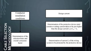
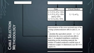
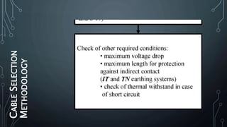
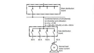
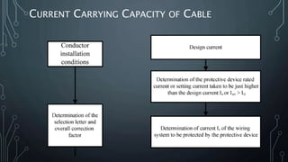
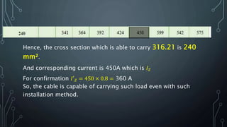
SlideShare a Scribd company logo
1 of 33
POWER CABLE
SELECTION
Presented By: Eng. Wesam Al-
Aslami
CALL: (+967)775497030, EMAIL: W.F.ALASLAMI@GMAIL.COM
OUTLINE
•INTRODUCTION
•CABLE PROPERTIES
•POWER CABLES SPECIFICATIONS
•CABLE SELECTION METHODOLOGY
•SUPPORTING EXAMPLE
INTRODUCTION
One of the hardest stages of a distribution project is CABLE
SELECTION, in which you wonder What is the proper CROSS
SECTION that you should use?
And this question brings out more and more related QUESTIONS like
What is the ENVIRONMENTAL CONDITIONS you are laying your
cable in?
Hmm.. Did you think that the method you’re LAYING CABLES may
effect cable ampacity?
Did you even noticed when cables are LAID TOGETHER feeding more
than one appliance are disturbing each other which make loses ?
What about “DISTANCE BETWEEN PHASES” does it effect cable
ampacity?
PROPERTIES OF SUCH IDEAL CABLE
For such cable it
Must be:
• Flexible.
• Able to Carry load current
without overheating.
• Within the permissible
voltage drop.
Give
• High degree of safety
• The cable must be provided
with suitable mechanical
protection
• The materials used in
manufacturing of cables
should be such that there is
complete chemical and
physical stability throughout.
• Non-inflammable
• Unaffected by acids and
POWER CABLES
SPECIFICATIONS
Power Cable Systems are usually characterized
by:
 Voltage classes
 Cable Construction
 Insulation Type
 Methods of Installation
 Environment
• Distribution secondary
systems
(Low Voltage) - 120 V to
4000 V
• Distribution primary system
(Medium Voltage) - 5 kV to
45 kV
• Transmission systems
• Conductor Material
Copper
Aluminum
• Conductor Shape
Single or multicore
Stranded or solid sectorial
conductors
Single or Multicore
For Distribution purpose:
• Polyvinyl chloride (PVC).
• Cross-linked poly-ethylene
(XLPE)
• On Trays
• In Ducts
• In Masonry
• In false ceilings
• In Buried Ducting
• Troughs built into
floor
 Methods of Installation
•On Trays
Basic Types:
1.Ladder.
2.Solid bottom
3.Trough
4.Channel
5.Wire Mesh
6.Single Rail
 Methods of Installation
•On Trays
•In Ducts
•In Masonry
•In false ceilings
•In Buried Ducting
•Troughs built into floor
POWER CABLES
SPECIFICATIONS
Power Cable Systems are usually characterized
by:
 Voltage classes
 Cable Construction
 Insulation Type
 Methods of Installation
 Environment
CABLESELECTION
METHODOLOGY
CABLESELECTION
METHODOLOGY
CABLESELECTION
METHODOLOGY
MAXIMUM DESIGN CURRENT
In the case of individual power supply to a device, the
current (IB) will be equal to the rated current of the
device being fed. On the other hand, if the wiring
system feeds several devices, the current (IB) will be
equal to the sum of currents absorbed, taking into
account the installation utilization and coincidence
factors.
MAXIMUM DESIGN CURRENT (𝐼 𝐵)
What if there is A COMPENSATION ? How shall we determine the
DESIGN CURRENT ? EXPLAIN.
Well,
If an assumption applied “Compensation in operation”.
CAPACITOR FAILURE WIRING SYSTEM IS PLACED OUT OF
SERVICE.
If an assumption applied “Compensation is out of service”.
CAPACITOR FAILURE  CONDUCTOR CROSS SECTION IS
sufficient to CARRY LOAD CURRENT.
SO…………………………………………………………………………………………………
MAXIMUM DESIGN CURRENT (𝐼 𝐵)
FACTORS EFFECTING MAXIMUM DESIGN CURRENT :
• POWER FACTOR AND EFFICIENCY FACTOR (a)
𝒔 =
𝑷
𝜼×𝒑.𝒇
in KVA  𝐀 =
𝟏
𝜼×𝒑.𝒇
• UTILIZATION FACTOR (b)
In an industrial installation, it is assumed that loads will never be
used at their full power level.
B = 0.75 for motors.
B = 1 for lighting and heating.
• COINCIDENCE FACTOR (c)
Use Coincidence factor c
Lighting 1
Lighting and air
conditioning 1
Power outlets 0.1 to 0.2 (for a number > 20)
MAXIMUM DESIGN CURRENT (𝐼 𝐵)
FACTORS EFFECTING MAXIMUM DESIGN CURRENT :
• COINCIDENCE FACTOR (c)
Number of circuits having
similar nominal currents
Coincidence factor
2 and 3 0.9
4 and 5 0.8
5 to 9 0.7
10 and more 0.6
• FUTURE EXPANSION FACTOR (d)
In the absence of precise indications, the value of 1.2 is often
used.
MAXIMUM DESIGN CURRENT (𝐼 𝑏)
THUS,
𝐼 𝐵 =
𝑃×𝑎×𝑏×𝑐×𝑑
3×𝑉
……for three phase loads.
𝐼 𝐵 =
𝑃×𝑎×𝑏×𝑐×𝑑
𝑉
……for single phase loads.
Subscripts identification
𝐼 𝐵 = Maximum design current Determined by Load.
Calculation
𝐼𝑆𝐶 = Short circuit current of 3 Phase Fault. Calculation
𝐼 𝑍 = Current carrying capacity of Selected Cable. Tables
× 𝒂𝒎𝒑𝒂𝒄𝒊𝒕𝒚. 𝒇
𝐼 𝑛 = Nominal or setting current of Protective Device.
Setting
𝐼𝑆𝐶𝐵 = Breaking capacityProtective Device. Setting
PROTECTIVE DEVICES
PROTECTIVE DEVICES
•Nominal or setting current
IB ≤ In ≤ IZ, which corresponds to zone a in
the figure.
•Conventional or overcurrent trip
 Case of CB
1. For domestic CB
I2 = 1.45In From standard IEC
898
2. For industrial CB
I2 = 1.3In From standard IEC 947-
2
 Case of Fuses
PROTECTIVE DEVICES
•Breaking capacity of circuit breaker.
𝐼𝑆𝐶𝐵 ≥ 𝐼𝑆𝐶3
Thus,
 𝐼 𝐵
 𝐼𝑆𝐶 Etap
 𝐼 𝑛
 𝐼𝑆𝐶𝐵
 𝐼2
𝐼 𝑍 Required to evaluate Cross
section
CURRENT CARRYING CAPACITY OF CABLE
𝐼 𝑍 depends on many factor according to the method of
installations in which many other factors show up.
How to obtain these factors ?
1. Define the installation method. From here
2. Gather the factors belong to such installation method. For
example f1,f5,f6 …etc according to the installation method.
3. Evaluate the overall correction factor f
4. Assume that the current should be carried by cable is
𝑰 𝑩
′
=
𝑰 𝑩
𝒇
5. From tables select the cross section which corresponds to a
current value greater than 𝑰 𝑩
′
. The values in the table show 𝐼 𝑍.
𝐼 𝑍 ≥ 𝑰 𝑩
′
6. Check if the cable able to carry load current by 𝐼′ 𝑍 = 𝐼 𝑍 × 𝑓
𝑖𝑛 𝑤ℎ𝑖𝑐ℎ 𝑰′ 𝒛 ≥ 𝑰 𝑩
CORRECTION FACTORS
• Ambient temperature rather than 30 °C (𝑓1).
• ground temperatures other than 20 °C (𝑓2).
• Soil resistivity for buried cables (𝑓3).
• Touching multi-core or groups of single-core cables
(𝒇 𝟒).
• Multi-core cables or groups of single-core cables
arranged in several layers (𝒇 𝟓).
• Number of conduits in air and their arrangement (𝒇 𝟔).
• conduits buried or built into concrete and their
arrangement (𝑓7).
• Non-touching buried conduits run horizontally or
vertically on the basis of one cable or group of 3 single-
core cables per conduit (𝑓8).
CROSS-SECTIONAL AREA OF PROTECTIVE
CONDUCTORS (PE)
According to IEC 364
The cross-sectional area of the PE conductor is defined in
relation to the cross-sectional area of the phases.
For 𝑆 𝑃ℎ𝑎𝑠𝑒 ≤ 16 𝑚𝑚2 , 𝑆 𝑃𝐸 = 𝑆 𝑃ℎ𝑎𝑠𝑒
For 16 𝑚𝑚2 < 𝑆 𝑃ℎ𝑎𝑠𝑒 ≤ 35 𝑚𝑚2 , 𝑆 𝑃𝐸 = 16 𝑚𝑚2
For 𝑆 𝑃ℎ𝑎𝑠𝑒 > 35 𝑚𝑚2 , 𝑆 𝑃𝐸 = 𝑆 𝑃ℎ𝑎𝑠𝑒 /2
• In the TT earthing system, the protective conductor
cross-sectional area may be limited to:
25 mm² for copper.
35 mm² for aluminum
NEUTRAL WIRE CROSS SECTIONAL AREA
Neutral wire cross section same as phase cross section when
𝑆 𝑝ℎ𝑎𝑠𝑒 ≤ 16 𝑚𝑚2 𝑓𝑜𝑟 𝑐𝑜𝑝𝑝𝑒𝑟 𝑐𝑎𝑏𝑙𝑒𝑠
𝑆 𝑝ℎ𝑎𝑠𝑒 ≤ 25 𝑚𝑚2 𝑓𝑜𝑟 𝐴𝑙𝑢𝑚𝑖𝑛𝑢𝑚 𝑐𝑎𝑏𝑙𝑒𝑠
Have cross section in any other cases for both copper or
aluminum.
𝑰 𝑩
′
=
𝑆 𝑝ℎ𝑎𝑠𝑒
𝟐
VOLTAGE DROP CHECK
∆𝑽 = 𝒃 𝒑 𝟏
𝑳
𝒔
𝒄𝒐𝒔 𝝋 + 𝝀𝑳 𝒔𝒊𝒏 𝝋 × 𝑰 𝑩
• Where:
• b : Coefficient (b=1 for three - phase circuit , b= 2 for single -
phase circuit).
• 𝒑 𝟏 : Conductor resistivity during normal service, i.e. 1.25 times that
at 20 °C
• (When: 𝒑 𝟏 = 0.0225 W mm²/m for copper, 𝒑 𝟏 = 0.036 W mm²/m
for aluminum).
• 𝒄𝒐𝒔 𝝋 : Power factor.
• (In the absence of specific indications we can take cos 𝜑 = 0.8 & sin 𝜑
= 0.6)
• 𝑰 𝑩 : Maximum design current, in amps
• 𝝀 : Reactance per unit length of the conductors, in W/m.
• The values of 𝝀 in LV are:
1. for three-core cables: 𝝀 = 0.08 × 10³
Ω/m
SUPPORTING EXAMPLE
A cable is laid from MDP to another panel board containing
many circuits, depending on the following data calculate
the proper cable cross section.
Given Data:
Voltage level = 380V, Ambient Temperature = 35 °C ,
N°=13
Length (L) = 12 m, Installation method  Perforated
Tray with letter E, installed in parallel with two other
circuits with no layers beside this cable tray.
Insulation type >> XLPE, Allowable voltage drop %  4%,
Panel Load = 224 KVA, assuming unity p.f and efficiency
Utilization factor all attached loads = 0.71
Coincidence factor = 0.95,
SOLUTION
1.DESIGN CURRENT
𝐼 𝐵 =
𝑃 × 𝑎 × 𝑏 × 𝑐 × 𝑑
3 × 𝑉
𝑎 = 1, 𝑏 = 0.75, 𝑐 = 0.95, 𝑑 = 1.2, 𝑉 = 0.38, 𝑃 = 224
𝐼 𝐵 =
244 × 1 × 0.75 × 0.95 × 1.2
3 × 0.38
= 316.97𝐴
2.PROTECTIVE DEVICE
Since circuit breakers are manufactured according to
standard values then the closest current to the design current is
320 A.
𝐼 𝑛 = 320 , 𝑆𝑒𝑡 =
316.97
320
= 0.99.
Since setting is close to unity, then the setting won’t change.
SOLUTION
3.CURRENT CARRYING CAPACITY OF CABLE .
𝐼′ 𝐵 =
𝐼 𝐵
𝑓
Installation method is “on perforated cable Tray with
letter E”, with ambient temperature of 35 °C
Factors effecting this method are 𝑓0 , 𝑓1 , 𝑓4 , 𝑓5
𝑓0 = 1, 𝑓1 = 0.91, 𝑓4 = 0.88, 𝑓5 = 1
Hence, equivalent of factors is 𝑓 = 1 × 0.91 × 0.88 × 1 =
0.8
𝐼′ 𝐵 =
316.97
0.8
= 396.21𝐴
From tables the cross section that could carry such load
is shown below
SOLUTION
3.CURRENT CARRYING CAPACITY OF CABLE .
𝐼′ 𝐵 =
𝐼 𝐵
𝑓
Installation method is “on perforated cable Tray with
letter E”, with ambient temperature of 35 °C
Factors effecting this method are 𝑓0 , 𝑓1 , 𝑓4 , 𝑓5
𝑓0 = 1, 𝑓1 = 0.91, 𝑓4 = 0.88, 𝑓5 = 1
0.91
Hence, the cross section which is able to carry 316.21 is 240
mm².
And corresponding current is 450A which is 𝐼 𝑍
For confirmation 𝐼′ 𝑍 = 450 × 0.8 = 360 A
So, the cable is capable of carrying such load even with such
installation method.
• You can continue the solution and you will find that the cable is
able to carry such current with less than 4% voltage drop
THANK YOU
CALL: (+967)775497030, EMAIL:
W.F.ALASLAMI@GMAIL.COM

More Related Content

What's hot

Commissioning of Electrical Equipment or systems.ppt
Commissioning of Electrical Equipment or systems.pptCommissioning of Electrical Equipment or systems.ppt
Commissioning of Electrical Equipment or systems.ppt
AlemayehuAsmare
 
Electrical grounding and earthing systems
Electrical grounding and earthing systemsElectrical grounding and earthing systems
Electrical grounding and earthing systems
Biswajit Pratihari
 

What's hot (20)

Overhead line work ppt
Overhead line work pptOverhead line work ppt
Overhead line work ppt
 
Substation Training presentation
Substation Training presentationSubstation Training presentation
Substation Training presentation
 
Installation, Testing and Troubleshooting of Transformers
Installation, Testing and Troubleshooting of TransformersInstallation, Testing and Troubleshooting of Transformers
Installation, Testing and Troubleshooting of Transformers
 
Cable
CableCable
Cable
 
Electrical Power substation
Electrical Power substationElectrical Power substation
Electrical Power substation
 
Earthing system
Earthing system   Earthing system
Earthing system
 
220 KV Substation Operation & Maintenance
220 KV Substation Operation & Maintenance220 KV Substation Operation & Maintenance
220 KV Substation Operation & Maintenance
 
Switchgear presentation
Switchgear presentationSwitchgear presentation
Switchgear presentation
 
Air circuit breakers
Air circuit breakersAir circuit breakers
Air circuit breakers
 
Switchgear and protection lecture 1
Switchgear and protection lecture 1Switchgear and protection lecture 1
Switchgear and protection lecture 1
 
Commissioning of Electrical Equipment or systems.ppt
Commissioning of Electrical Equipment or systems.pptCommissioning of Electrical Equipment or systems.ppt
Commissioning of Electrical Equipment or systems.ppt
 
Under ground cables presention
Under ground cables presentionUnder ground cables presention
Under ground cables presention
 
Protection & switchgear
Protection & switchgear   Protection & switchgear
Protection & switchgear
 
Electrical grounding and earthing systems
Electrical grounding and earthing systemsElectrical grounding and earthing systems
Electrical grounding and earthing systems
 
Switchgear presentation
Switchgear presentationSwitchgear presentation
Switchgear presentation
 
Presentation on cables
Presentation on cablesPresentation on cables
Presentation on cables
 
Supply systems
Supply systemsSupply systems
Supply systems
 
Ps ppt by saran
Ps  ppt by saranPs  ppt by saran
Ps ppt by saran
 
33kv substation
33kv substation33kv substation
33kv substation
 
Types of Cable.PPT
Types of Cable.PPTTypes of Cable.PPT
Types of Cable.PPT
 

Similar to Power cable selection, cable selection Methodology

Cable sizing to withstand short circuit current
Cable sizing to withstand short circuit currentCable sizing to withstand short circuit current
Cable sizing to withstand short circuit current
Leonardo ENERGY
 
changwon MVP, EMDB, SMDB & DB
changwon MVP, EMDB, SMDB & DBchangwon MVP, EMDB, SMDB & DB
changwon MVP, EMDB, SMDB & DB
Sheikh Imran
 
EEE- BEE601 - TRANSMISSION AND DISTRIBUTION- Dr. V. Jayalakshmi.pdf
EEE- BEE601 - TRANSMISSION AND DISTRIBUTION- Dr. V. Jayalakshmi.pdfEEE- BEE601 - TRANSMISSION AND DISTRIBUTION- Dr. V. Jayalakshmi.pdf
EEE- BEE601 - TRANSMISSION AND DISTRIBUTION- Dr. V. Jayalakshmi.pdf
AnbarasuL1
 
Electrical Systems Safety
Electrical Systems SafetyElectrical Systems Safety
Electrical Systems Safety
Talia Carbis
 

Similar to Power cable selection, cable selection Methodology (20)

Ehv line design
Ehv line designEhv line design
Ehv line design
 
Cable sizing to withstand short circuit current
Cable sizing to withstand short circuit currentCable sizing to withstand short circuit current
Cable sizing to withstand short circuit current
 
GUIDE TO OVERALL OVERHEAD LINE DESIGN
GUIDE TO OVERALL OVERHEAD LINE  DESIGNGUIDE TO OVERALL OVERHEAD LINE  DESIGN
GUIDE TO OVERALL OVERHEAD LINE DESIGN
 
220kv-switch-yard-ppt.pptx
220kv-switch-yard-ppt.pptx220kv-switch-yard-ppt.pptx
220kv-switch-yard-ppt.pptx
 
Busbar Presentation2.pdf
Busbar Presentation2.pdfBusbar Presentation2.pdf
Busbar Presentation2.pdf
 
Lecture 1_Reactive Elements-1 like inductorand capacitor .pdf
Lecture 1_Reactive Elements-1 like inductorand capacitor .pdfLecture 1_Reactive Elements-1 like inductorand capacitor .pdf
Lecture 1_Reactive Elements-1 like inductorand capacitor .pdf
 
changwon MVP, EMDB, SMDB & DB
changwon MVP, EMDB, SMDB & DBchangwon MVP, EMDB, SMDB & DB
changwon MVP, EMDB, SMDB & DB
 
H046044147
H046044147H046044147
H046044147
 
EEE- BEE601 - TRANSMISSION AND DISTRIBUTION- Dr. V. Jayalakshmi.pdf
EEE- BEE601 - TRANSMISSION AND DISTRIBUTION- Dr. V. Jayalakshmi.pdfEEE- BEE601 - TRANSMISSION AND DISTRIBUTION- Dr. V. Jayalakshmi.pdf
EEE- BEE601 - TRANSMISSION AND DISTRIBUTION- Dr. V. Jayalakshmi.pdf
 
EEE- BEE601 - TRANSMISSION AND DISTRIBUTION- Dr. V. Jayalakshmi.pdf
EEE- BEE601 - TRANSMISSION AND DISTRIBUTION- Dr. V. Jayalakshmi.pdfEEE- BEE601 - TRANSMISSION AND DISTRIBUTION- Dr. V. Jayalakshmi.pdf
EEE- BEE601 - TRANSMISSION AND DISTRIBUTION- Dr. V. Jayalakshmi.pdf
 
Mod5part1
Mod5part1Mod5part1
Mod5part1
 
Concept of energy transmission & distribution
Concept of energy transmission & distribution Concept of energy transmission & distribution
Concept of energy transmission & distribution
 
Power cable - Installation methods
Power cable - Installation methodsPower cable - Installation methods
Power cable - Installation methods
 
Electrical Systems Safety
Electrical Systems SafetyElectrical Systems Safety
Electrical Systems Safety
 
presentations for the project of solar energy
presentations for the project of solar energypresentations for the project of solar energy
presentations for the project of solar energy
 
CHAPTER 2 Design of Building Electrical Systems (2).pptx.pptx
CHAPTER 2 Design of Building Electrical Systems (2).pptx.pptxCHAPTER 2 Design of Building Electrical Systems (2).pptx.pptx
CHAPTER 2 Design of Building Electrical Systems (2).pptx.pptx
 
f2001_landinger.ppt
f2001_landinger.pptf2001_landinger.ppt
f2001_landinger.ppt
 
Generator grounding
Generator groundingGenerator grounding
Generator grounding
 
Sinusoidal Response of RC & RL Circuits
Sinusoidal Response of RC & RL CircuitsSinusoidal Response of RC & RL Circuits
Sinusoidal Response of RC & RL Circuits
 
Grounding in power system
Grounding in power systemGrounding in power system
Grounding in power system
 

Recently uploaded

Standard vs Custom Battery Packs - Decoding the Power Play
Standard vs Custom Battery Packs - Decoding the Power PlayStandard vs Custom Battery Packs - Decoding the Power Play
Standard vs Custom Battery Packs - Decoding the Power Play
Epec Engineered Technologies
 
Digital Communication Essentials: DPCM, DM, and ADM .pptx
Digital Communication Essentials: DPCM, DM, and ADM .pptxDigital Communication Essentials: DPCM, DM, and ADM .pptx
Digital Communication Essentials: DPCM, DM, and ADM .pptx
pritamlangde
 
"Lesotho Leaps Forward: A Chronicle of Transformative Developments"
"Lesotho Leaps Forward: A Chronicle of Transformative Developments""Lesotho Leaps Forward: A Chronicle of Transformative Developments"
"Lesotho Leaps Forward: A Chronicle of Transformative Developments"
mphochane1998
 
Integrated Test Rig For HTFE-25 - Neometrix
Integrated Test Rig For HTFE-25 - NeometrixIntegrated Test Rig For HTFE-25 - Neometrix
Integrated Test Rig For HTFE-25 - Neometrix
Neometrix_Engineering_Pvt_Ltd
 
Hospital management system project report.pdf
Hospital management system project report.pdfHospital management system project report.pdf
Hospital management system project report.pdf
Kamal Acharya
 

Recently uploaded (20)

HOA1&2 - Module 3 - PREHISTORCI ARCHITECTURE OF KERALA.pptx
HOA1&2 - Module 3 - PREHISTORCI ARCHITECTURE OF KERALA.pptxHOA1&2 - Module 3 - PREHISTORCI ARCHITECTURE OF KERALA.pptx
HOA1&2 - Module 3 - PREHISTORCI ARCHITECTURE OF KERALA.pptx
 
8086 Microprocessor Architecture: 16-bit microprocessor
8086 Microprocessor Architecture: 16-bit microprocessor8086 Microprocessor Architecture: 16-bit microprocessor
8086 Microprocessor Architecture: 16-bit microprocessor
 
Electromagnetic relays used for power system .pptx
Electromagnetic relays used for power system .pptxElectromagnetic relays used for power system .pptx
Electromagnetic relays used for power system .pptx
 
Standard vs Custom Battery Packs - Decoding the Power Play
Standard vs Custom Battery Packs - Decoding the Power PlayStandard vs Custom Battery Packs - Decoding the Power Play
Standard vs Custom Battery Packs - Decoding the Power Play
 
Signal Processing and Linear System Analysis
Signal Processing and Linear System AnalysisSignal Processing and Linear System Analysis
Signal Processing and Linear System Analysis
 
Memory Interfacing of 8086 with DMA 8257
Memory Interfacing of 8086 with DMA 8257Memory Interfacing of 8086 with DMA 8257
Memory Interfacing of 8086 with DMA 8257
 
Online electricity billing project report..pdf
Online electricity billing project report..pdfOnline electricity billing project report..pdf
Online electricity billing project report..pdf
 
fitting shop and tools used in fitting shop .ppt
fitting shop and tools used in fitting shop .pptfitting shop and tools used in fitting shop .ppt
fitting shop and tools used in fitting shop .ppt
 
Computer Networks Basics of Network Devices
Computer Networks  Basics of Network DevicesComputer Networks  Basics of Network Devices
Computer Networks Basics of Network Devices
 
Max. shear stress theory-Maximum Shear Stress Theory ​ Maximum Distortional ...
Max. shear stress theory-Maximum Shear Stress Theory ​  Maximum Distortional ...Max. shear stress theory-Maximum Shear Stress Theory ​  Maximum Distortional ...
Max. shear stress theory-Maximum Shear Stress Theory ​ Maximum Distortional ...
 
Digital Communication Essentials: DPCM, DM, and ADM .pptx
Digital Communication Essentials: DPCM, DM, and ADM .pptxDigital Communication Essentials: DPCM, DM, and ADM .pptx
Digital Communication Essentials: DPCM, DM, and ADM .pptx
 
School management system project Report.pdf
School management system project Report.pdfSchool management system project Report.pdf
School management system project Report.pdf
 
Online food ordering system project report.pdf
Online food ordering system project report.pdfOnline food ordering system project report.pdf
Online food ordering system project report.pdf
 
"Lesotho Leaps Forward: A Chronicle of Transformative Developments"
"Lesotho Leaps Forward: A Chronicle of Transformative Developments""Lesotho Leaps Forward: A Chronicle of Transformative Developments"
"Lesotho Leaps Forward: A Chronicle of Transformative Developments"
 
Augmented Reality (AR) with Augin Software.pptx
Augmented Reality (AR) with Augin Software.pptxAugmented Reality (AR) with Augin Software.pptx
Augmented Reality (AR) with Augin Software.pptx
 
Path loss model, OKUMURA Model, Hata Model
Path loss model, OKUMURA Model, Hata ModelPath loss model, OKUMURA Model, Hata Model
Path loss model, OKUMURA Model, Hata Model
 
Integrated Test Rig For HTFE-25 - Neometrix
Integrated Test Rig For HTFE-25 - NeometrixIntegrated Test Rig For HTFE-25 - Neometrix
Integrated Test Rig For HTFE-25 - Neometrix
 
Hospital management system project report.pdf
Hospital management system project report.pdfHospital management system project report.pdf
Hospital management system project report.pdf
 
Design For Accessibility: Getting it right from the start
Design For Accessibility: Getting it right from the startDesign For Accessibility: Getting it right from the start
Design For Accessibility: Getting it right from the start
 
Computer Graphics Introduction To Curves
Computer Graphics Introduction To CurvesComputer Graphics Introduction To Curves
Computer Graphics Introduction To Curves
 

Power cable selection, cable selection Methodology

  • 1. POWER CABLE SELECTION Presented By: Eng. Wesam Al- Aslami CALL: (+967)775497030, EMAIL: W.F.ALASLAMI@GMAIL.COM
  • 2. OUTLINE •INTRODUCTION •CABLE PROPERTIES •POWER CABLES SPECIFICATIONS •CABLE SELECTION METHODOLOGY •SUPPORTING EXAMPLE
  • 3. INTRODUCTION One of the hardest stages of a distribution project is CABLE SELECTION, in which you wonder What is the proper CROSS SECTION that you should use? And this question brings out more and more related QUESTIONS like What is the ENVIRONMENTAL CONDITIONS you are laying your cable in? Hmm.. Did you think that the method you’re LAYING CABLES may effect cable ampacity? Did you even noticed when cables are LAID TOGETHER feeding more than one appliance are disturbing each other which make loses ? What about “DISTANCE BETWEEN PHASES” does it effect cable ampacity?
  • 4. PROPERTIES OF SUCH IDEAL CABLE For such cable it Must be: • Flexible. • Able to Carry load current without overheating. • Within the permissible voltage drop. Give • High degree of safety • The cable must be provided with suitable mechanical protection • The materials used in manufacturing of cables should be such that there is complete chemical and physical stability throughout. • Non-inflammable • Unaffected by acids and
  • 5. POWER CABLES SPECIFICATIONS Power Cable Systems are usually characterized by:  Voltage classes  Cable Construction  Insulation Type  Methods of Installation  Environment • Distribution secondary systems (Low Voltage) - 120 V to 4000 V • Distribution primary system (Medium Voltage) - 5 kV to 45 kV • Transmission systems • Conductor Material Copper Aluminum • Conductor Shape Single or multicore Stranded or solid sectorial conductors Single or Multicore For Distribution purpose: • Polyvinyl chloride (PVC). • Cross-linked poly-ethylene (XLPE) • On Trays • In Ducts • In Masonry • In false ceilings • In Buried Ducting • Troughs built into floor
  • 6.  Methods of Installation •On Trays Basic Types: 1.Ladder. 2.Solid bottom 3.Trough 4.Channel 5.Wire Mesh 6.Single Rail
  • 7.  Methods of Installation •On Trays •In Ducts •In Masonry •In false ceilings •In Buried Ducting •Troughs built into floor
  • 8. POWER CABLES SPECIFICATIONS Power Cable Systems are usually characterized by:  Voltage classes  Cable Construction  Insulation Type  Methods of Installation  Environment
  • 12. MAXIMUM DESIGN CURRENT In the case of individual power supply to a device, the current (IB) will be equal to the rated current of the device being fed. On the other hand, if the wiring system feeds several devices, the current (IB) will be equal to the sum of currents absorbed, taking into account the installation utilization and coincidence factors.
  • 13. MAXIMUM DESIGN CURRENT (𝐼 𝐵) What if there is A COMPENSATION ? How shall we determine the DESIGN CURRENT ? EXPLAIN. Well, If an assumption applied “Compensation in operation”. CAPACITOR FAILURE WIRING SYSTEM IS PLACED OUT OF SERVICE. If an assumption applied “Compensation is out of service”. CAPACITOR FAILURE  CONDUCTOR CROSS SECTION IS sufficient to CARRY LOAD CURRENT. SO…………………………………………………………………………………………………
  • 14. MAXIMUM DESIGN CURRENT (𝐼 𝐵) FACTORS EFFECTING MAXIMUM DESIGN CURRENT : • POWER FACTOR AND EFFICIENCY FACTOR (a) 𝒔 = 𝑷 𝜼×𝒑.𝒇 in KVA  𝐀 = 𝟏 𝜼×𝒑.𝒇 • UTILIZATION FACTOR (b) In an industrial installation, it is assumed that loads will never be used at their full power level. B = 0.75 for motors. B = 1 for lighting and heating. • COINCIDENCE FACTOR (c) Use Coincidence factor c Lighting 1 Lighting and air conditioning 1 Power outlets 0.1 to 0.2 (for a number > 20)
  • 15. MAXIMUM DESIGN CURRENT (𝐼 𝐵) FACTORS EFFECTING MAXIMUM DESIGN CURRENT : • COINCIDENCE FACTOR (c) Number of circuits having similar nominal currents Coincidence factor 2 and 3 0.9 4 and 5 0.8 5 to 9 0.7 10 and more 0.6 • FUTURE EXPANSION FACTOR (d) In the absence of precise indications, the value of 1.2 is often used.
  • 16. MAXIMUM DESIGN CURRENT (𝐼 𝑏) THUS, 𝐼 𝐵 = 𝑃×𝑎×𝑏×𝑐×𝑑 3×𝑉 ……for three phase loads. 𝐼 𝐵 = 𝑃×𝑎×𝑏×𝑐×𝑑 𝑉 ……for single phase loads. Subscripts identification 𝐼 𝐵 = Maximum design current Determined by Load. Calculation 𝐼𝑆𝐶 = Short circuit current of 3 Phase Fault. Calculation 𝐼 𝑍 = Current carrying capacity of Selected Cable. Tables × 𝒂𝒎𝒑𝒂𝒄𝒊𝒕𝒚. 𝒇 𝐼 𝑛 = Nominal or setting current of Protective Device. Setting 𝐼𝑆𝐶𝐵 = Breaking capacityProtective Device. Setting
  • 18. PROTECTIVE DEVICES •Nominal or setting current IB ≤ In ≤ IZ, which corresponds to zone a in the figure. •Conventional or overcurrent trip  Case of CB 1. For domestic CB I2 = 1.45In From standard IEC 898 2. For industrial CB I2 = 1.3In From standard IEC 947- 2  Case of Fuses
  • 19. PROTECTIVE DEVICES •Breaking capacity of circuit breaker. 𝐼𝑆𝐶𝐵 ≥ 𝐼𝑆𝐶3 Thus,  𝐼 𝐵  𝐼𝑆𝐶 Etap  𝐼 𝑛  𝐼𝑆𝐶𝐵  𝐼2 𝐼 𝑍 Required to evaluate Cross section
  • 21. CURRENT CARRYING CAPACITY OF CABLE 𝐼 𝑍 depends on many factor according to the method of installations in which many other factors show up. How to obtain these factors ? 1. Define the installation method. From here 2. Gather the factors belong to such installation method. For example f1,f5,f6 …etc according to the installation method. 3. Evaluate the overall correction factor f 4. Assume that the current should be carried by cable is 𝑰 𝑩 ′ = 𝑰 𝑩 𝒇 5. From tables select the cross section which corresponds to a current value greater than 𝑰 𝑩 ′ . The values in the table show 𝐼 𝑍. 𝐼 𝑍 ≥ 𝑰 𝑩 ′ 6. Check if the cable able to carry load current by 𝐼′ 𝑍 = 𝐼 𝑍 × 𝑓 𝑖𝑛 𝑤ℎ𝑖𝑐ℎ 𝑰′ 𝒛 ≥ 𝑰 𝑩
  • 22. CORRECTION FACTORS • Ambient temperature rather than 30 °C (𝑓1). • ground temperatures other than 20 °C (𝑓2). • Soil resistivity for buried cables (𝑓3). • Touching multi-core or groups of single-core cables (𝒇 𝟒). • Multi-core cables or groups of single-core cables arranged in several layers (𝒇 𝟓). • Number of conduits in air and their arrangement (𝒇 𝟔). • conduits buried or built into concrete and their arrangement (𝑓7). • Non-touching buried conduits run horizontally or vertically on the basis of one cable or group of 3 single- core cables per conduit (𝑓8).
  • 23. CROSS-SECTIONAL AREA OF PROTECTIVE CONDUCTORS (PE) According to IEC 364 The cross-sectional area of the PE conductor is defined in relation to the cross-sectional area of the phases. For 𝑆 𝑃ℎ𝑎𝑠𝑒 ≤ 16 𝑚𝑚2 , 𝑆 𝑃𝐸 = 𝑆 𝑃ℎ𝑎𝑠𝑒 For 16 𝑚𝑚2 < 𝑆 𝑃ℎ𝑎𝑠𝑒 ≤ 35 𝑚𝑚2 , 𝑆 𝑃𝐸 = 16 𝑚𝑚2 For 𝑆 𝑃ℎ𝑎𝑠𝑒 > 35 𝑚𝑚2 , 𝑆 𝑃𝐸 = 𝑆 𝑃ℎ𝑎𝑠𝑒 /2 • In the TT earthing system, the protective conductor cross-sectional area may be limited to: 25 mm² for copper. 35 mm² for aluminum
  • 24. NEUTRAL WIRE CROSS SECTIONAL AREA Neutral wire cross section same as phase cross section when 𝑆 𝑝ℎ𝑎𝑠𝑒 ≤ 16 𝑚𝑚2 𝑓𝑜𝑟 𝑐𝑜𝑝𝑝𝑒𝑟 𝑐𝑎𝑏𝑙𝑒𝑠 𝑆 𝑝ℎ𝑎𝑠𝑒 ≤ 25 𝑚𝑚2 𝑓𝑜𝑟 𝐴𝑙𝑢𝑚𝑖𝑛𝑢𝑚 𝑐𝑎𝑏𝑙𝑒𝑠 Have cross section in any other cases for both copper or aluminum. 𝑰 𝑩 ′ = 𝑆 𝑝ℎ𝑎𝑠𝑒 𝟐
  • 25.
  • 26. VOLTAGE DROP CHECK ∆𝑽 = 𝒃 𝒑 𝟏 𝑳 𝒔 𝒄𝒐𝒔 𝝋 + 𝝀𝑳 𝒔𝒊𝒏 𝝋 × 𝑰 𝑩 • Where: • b : Coefficient (b=1 for three - phase circuit , b= 2 for single - phase circuit). • 𝒑 𝟏 : Conductor resistivity during normal service, i.e. 1.25 times that at 20 °C • (When: 𝒑 𝟏 = 0.0225 W mm²/m for copper, 𝒑 𝟏 = 0.036 W mm²/m for aluminum). • 𝒄𝒐𝒔 𝝋 : Power factor. • (In the absence of specific indications we can take cos 𝜑 = 0.8 & sin 𝜑 = 0.6) • 𝑰 𝑩 : Maximum design current, in amps • 𝝀 : Reactance per unit length of the conductors, in W/m. • The values of 𝝀 in LV are: 1. for three-core cables: 𝝀 = 0.08 × 10³ Ω/m
  • 27. SUPPORTING EXAMPLE A cable is laid from MDP to another panel board containing many circuits, depending on the following data calculate the proper cable cross section. Given Data: Voltage level = 380V, Ambient Temperature = 35 °C , N°=13 Length (L) = 12 m, Installation method  Perforated Tray with letter E, installed in parallel with two other circuits with no layers beside this cable tray. Insulation type >> XLPE, Allowable voltage drop %  4%, Panel Load = 224 KVA, assuming unity p.f and efficiency Utilization factor all attached loads = 0.71 Coincidence factor = 0.95,
  • 28. SOLUTION 1.DESIGN CURRENT 𝐼 𝐵 = 𝑃 × 𝑎 × 𝑏 × 𝑐 × 𝑑 3 × 𝑉 𝑎 = 1, 𝑏 = 0.75, 𝑐 = 0.95, 𝑑 = 1.2, 𝑉 = 0.38, 𝑃 = 224 𝐼 𝐵 = 244 × 1 × 0.75 × 0.95 × 1.2 3 × 0.38 = 316.97𝐴 2.PROTECTIVE DEVICE Since circuit breakers are manufactured according to standard values then the closest current to the design current is 320 A. 𝐼 𝑛 = 320 , 𝑆𝑒𝑡 = 316.97 320 = 0.99. Since setting is close to unity, then the setting won’t change.
  • 29. SOLUTION 3.CURRENT CARRYING CAPACITY OF CABLE . 𝐼′ 𝐵 = 𝐼 𝐵 𝑓 Installation method is “on perforated cable Tray with letter E”, with ambient temperature of 35 °C Factors effecting this method are 𝑓0 , 𝑓1 , 𝑓4 , 𝑓5 𝑓0 = 1, 𝑓1 = 0.91, 𝑓4 = 0.88, 𝑓5 = 1 Hence, equivalent of factors is 𝑓 = 1 × 0.91 × 0.88 × 1 = 0.8 𝐼′ 𝐵 = 316.97 0.8 = 396.21𝐴 From tables the cross section that could carry such load is shown below SOLUTION 3.CURRENT CARRYING CAPACITY OF CABLE . 𝐼′ 𝐵 = 𝐼 𝐵 𝑓 Installation method is “on perforated cable Tray with letter E”, with ambient temperature of 35 °C Factors effecting this method are 𝑓0 , 𝑓1 , 𝑓4 , 𝑓5 𝑓0 = 1, 𝑓1 = 0.91, 𝑓4 = 0.88, 𝑓5 = 1 0.91
  • 30.
  • 31. Hence, the cross section which is able to carry 316.21 is 240 mm². And corresponding current is 450A which is 𝐼 𝑍 For confirmation 𝐼′ 𝑍 = 450 × 0.8 = 360 A So, the cable is capable of carrying such load even with such installation method.
  • 32. • You can continue the solution and you will find that the cable is able to carry such current with less than 4% voltage drop
  • 33. THANK YOU CALL: (+967)775497030, EMAIL: W.F.ALASLAMI@GMAIL.COM

Editor's Notes

  1. the type of conductor is selected according to mechanical resistance, degree of insulation and difficulty of installation ( The choice depends on cost, dimension and weight requirements, resistance to corrosive environments (chemical reagents or oxidizing elements). In general, the carrying capacity I copper is 30% greater than of an aluminum conductor of the same cross section. An aluminum conductor of the same cross section has an electrical resistance about 60% higher and a weight half to one third lower than a copper conductor. the insulation material affects the maximum temperature under normal and short-circuit conditions