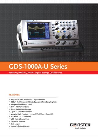
Digital Storage Oscilloscope - GDS-1000A-U Series
•
0 likes•43 views

The GDS-1000A-U series provide a unique solution. The GDS-1000A-U Digital Storage Oscilloscope lineup includes GDS-1152A-U, GDS-1102A-U and GDS-1072A-U three models. For more information, please visit- https://www.spiengineers.com/portfolio/gds-1000a-u/

Recommended
Recommended
More Related Content
What's hot
What's hot (13)
Similar to Digital Storage Oscilloscope - GDS-1000A-U Series
Similar to Digital Storage Oscilloscope - GDS-1000A-U Series (20)
More from SPI Engineers
More from SPI Engineers (14)
Recently uploaded
Recently uploaded (20)
Digital Storage Oscilloscope - GDS-1000A-U Series
- 1. .ai
- 2. It's all about the memory About MemoryPrime Technology What is the single feature lacking from most digital storage oscilloscopes? Adequate memory depth. Is the memory depth of your DSO large enough? With 2M points of memory, the GDS-1000A-U has the capability to acquire far more waveform data compared to other DSOs in the same performance range. The 1GSa/s sampling rate and 2M point memory plays an extremely powerful role for single-shot waveform capture. When the single-shot waveform is triggered and captured, you are able to check and see the single-shot event without losing any detailed information. A DSO, with a high sampling rate but short memory, can't capture a single shot waveform as well as the GDS-1000A-U. Traditional DSO 2.5k Memory Waveform Display GDS-1000A-U 2Mega Memory Waveform Display Single-Shot Waveform Capture Expand Expand Expand Expand GDS-1000A-U Series Others Others 1GSa/s 750MSa/s 500MS/s 250MSa/s 1MSa/s SampleRate 25ns/div 250ns/div 2.5us/div 25us/div 250us/div 2.5ms/div Discover Deep Memory Performance with the GDS-1000A-U Series The GDS-1000A-U 150/100/70MHz dual-channel digital storage oscilloscope series inherits the passionate design and strong value to traditional GW Instek DSOs. The series features 1GS/s real-time sampling rate, 2M memory length, USB remote interface, high resolution color TFT display, and GW Instek's user-friendly interface. Quality design and powerful features combine to create a powerful tool for waveform capture and analysis. displaying an input signal completely or comparing the relative relationship between signals accurately due to memory constraints. After all, the waveform record length and the sample rate of a DSO are tied to memory depth, and only the combination of a high sample rate and a long record length can make detailed waveform analysis possible. Assuming a constant sample rate, the more memory a DSO has, the longer the signal can be displayed. With the increasing complexity of signals, traditional digital storage oscilloscopes don't have the capability of Conversely, assuming a limited memory depth, a signal will be observed for a shorter time with a faster sample rate. In order to fully utilize the advantage of 2M points of memory without sacrificing the waveform update rate, the GDS-1000A-U adopts Memory Prime technology , Memory Prime uses a high speed signal processor in parallel with a CPU to increase the waveform reconstruction speed. Using a high Speed signal processor and 2M points of memory, the GDS-1000A-U is able to run at the maximum sampling speed of 1GSa/s under a wide range of time base selections (100us/div ~ 25ns/div). This unparalleled performance creates a significant differentiation compared to all other economic DSO products available in the market today. The sample rate of a DSO is closely related to memory size. Shallow memory digital storage oscilloscopes compromise the sample rate over a larger time base range as there is not enough memory to display the signal on the screen at the maximum sample rate. For example, a digital storage oscilloscope with a sample rate of 1GSa and a 2.5k point memory length can operate with a horizontal sweep speed below 20ns/div, but only by reducing the sampling rate accordingly. When the sample rate is reduced, there is a greater possibility that critical details get omitted. However with a larger memory depth, a high sampling rate can be maintained over a wider horizontal range. As illustrated, the GDS-1000A-U Series are able to maintain a sampling rate of 1Ga/S over 12 horizontal ranges, superior to that of other oscilloscopes with a 2.5k memory depth. Utilizing a greater memory depth, the GDS-1000A-U Series allows you to design and debug your projects more effectively.
- 3. A. C. EASY TO USE 27 Automatic Measurement Functions Delay On Delay Off FFTrms MeasurementFFT Measurement D. B. Expand by GroundOriginal SignalOriginal Signal Expand by Center The full-featured Acquisition mode and 27 auto measurement functions help users to measure captured waveform parameters accurately. The advanced Auto-Set function enables the GDS-1000A-U Series to capture waveforms automatically and display them quickly. To observe the fundamental and harmonic components of a signal, the FFT math function on a digital storage oscilloscope is often used. Typically, the traditional unit of the FFT is the decibel (dB). However, when using dB it is sometimes difficult to identify the fundamental frequency of a signal from a noisy For convenient waveform observation and analysis, the GDS- 1000A-U Series includes Delay On/Off functions; usually seen only in higher end products. With Delay On, a signal can be observed from an offset of the trigger point. With this feature, the horizontal scale and thus waveform scale can be expanded and centered on the delay point, but not at the trigger point. This allows a signal to be observed in detail where needed. * With Delay On, the waveform scale is expanded from the center of the screen, With Delay Off, the waveform scale is expanded from the trigger point. In a DSO, " AC Coupling " is normally used to isolate the AC components of a signal by blocking the DC components. This is useful to see a signal with a small AC component that is offset with a large DC voltage. With AC coupling to block the DC voltage, small AC waveforms can be observed from the center of the screen for measurement or examination. However, capacitive loading under AC coupling mode may cause waveform distortion as low frequency components may become degraded, frequency critical applications. The Expand by Ground and Center functions are convenient tools to expand a waveform vertically. With this feature, the vertical scale of a waveform can be expanded either from the ground reference or from the center of the screen without causing capacitive loading. MATH Functions OBSERVATION-DELAY ON/ OFF OBSERVATION-EXPAND BY GROUND/CENTER With addition, subtraction, multiplication and FFT math functions, the GDS-1000A-U Series keeps users aware of measurement results by constantly updating data. With minimal calculation, the GDS- 1000A-U Series can provide sufficient testing information. FFT / FFTrms / ZOOM FFT MEASUREMENT spectrum. With the FFTrms function, The he GDS-1000A-U Series can clearly display the fundamental frequency of an acquired waveform. Zoom FFT provides users with observation flexibility that they can move FFT waveform horizontally and zoom in it up to 20X to investigate details of FFT signal. Zoom FFT Measurement
- 4. G. PRIME FEATURES MemoryPrime technology allows a maximum of 2M points of waveform data. For engineers, analyzing a considerable amount of data can be an extremely challenging task. To assist engineers in analyzing waveforms quicker, we provide Horizontal Page Skip and Set Time Mark functionalities . This lets engineers take full advantage of the 2M memory depth. A built-in Autoset function on a digital oscilloscope gives engineers remarkable convenience. With the complexities of product features, traditional auto measurement information is inadequate for modern measurement needs. The new Cursor Gating feature allows you to mark an area with cursors for auto measurement. Auto Measurement Gating There is a diverse range of test probes currently on the market such as passive, differential, and electrical probes. The attenuation ratio of each probe type also differs greatly. To ensure compatibility, probe attenuation ratios of 0.1X to 2000X as well as voltage and current probes as supported with the GDS-1000A-U. Flexible Probe Factor Setting Template EditingData Logger Setup Go/NoGo TestData Logger furn ON Fast Horizontal Position Mark and Search Using a USB port coupled with FreeWave remote monitoring software is the easiest and most convenient way to capture data from the GDS- 1000A-U. With FreeWave, a screenshot can be saved as an image file (.bmp/.jpg),waveform data(.csv)can be logged and movie files(.wmv) can be recorded in real-time. Not only can FreeWave monitor and record waveforms over a long period of time, but previously recorded waveforms can also be observed. Instrument settings can even be configured without the need to learn incomprehensible command line syntax. With the simple user interface and robust features, FreeWave allows you to get the most out of the GDS-1000A-U with little effort. H. I.PC REMOTE CONTROL SOFTWARE GUARANTEED PROTECTION By providing the Global Lifetime Warranty Program for GDS-1000A-U digital storage oscilloscope series, we believe you can have high confidence in the quality of each GDS-1000A-U DSO. By purchasing a GDS-1000A-U you can be assured of a highly economical, low maintenance, quality DSO backed with the protection of the Lifetime Warranty program. The Lifetime Warranty Program guarantees customers will be supported regardless of their location. Customers will receive at least 5 years of full support even after production has ceased. For more details and applicable conditions regarding the Lifetime Service program, please visit the GW Instek website or consult your nearest distributor.www.gwinstek.com/llw Buy a GDS-1000A-U Series DSO, get a Limited Lifetime Warranty E. F.USB HOST & DATA LOGGER GO/NOGO FUNCTION USB host function enables user to easily store waveform setting, data, or image on USB flash disk. Furthermore, data logger can continue monitoring input signals and storing their waveform data in USB flash disk when trigger conditions are met, saving users’ efforts to tracking signals manually and allowing them to analyze and observe waveform data afterwards. Go/NoGo testing function check whether the incoming signal violates the user-defined template. Users can easily define this template by setting the tolerance ratio to determine violation conditions. Go/NoGo testing can either keep counting violation number or stop testing when violation conditions are met.
- 5. MODEL DISPLAY DEVICE RECORD LENGTH SAMPLE RATE BANDWIDTH CHANNELS USB HOST USB DEVICE CALIBRATION OUTPUT GDS-1072A-UGDS-1102A-UGDS-1152A-U 150MHz 100MHz 70MHz 2 SELECTION GUIDE Standard 2 Mega Points 1GSa/s(Real-time) 25GSa/s(Equivaleut-time) 5.7" TFT Color LCD PANEL INTRODUCTION 150/100/70 MHz Digital Storage Oscilloscope GDS-1000A-U Series 1. Stunning Display 4. Vertical Controls 3. Advanced Triggers 2. Memory and Interface 5. Autoset Enable/ Disable 6. Enhanced CAL signal output To help students learn how to use an oscilloscope manually, the Autoset function can be disabled on the GDS-1000A-U Series. GDS-1000A-U Series has an enhanced 1kHz calibration signal. Its output frequency is adjustable from 1 kHz to 100 kHz as well as the duty cycle adjustable by 5% ~ 95%. The 5.7" TFT color LCD greatly enhances the GDS-1000A-U display performance letting you see the waveform details clearly from a broad range of view-angle. Separate vertical controls for each channel allows for simple and fast operation. There is no longer any need to share one set of vertical controls for both channels. Quick setting to capture any signal of interest with Normal, Single, Force, Pulse Width and Video line selectable triggers. Up to 17 waveforms can be saved into the internal memory to be recalled later and compared. USB Host port provides a safe environment for data storage and transfer of measurement results, and the USB device port interface allows remote control for direct printing to PictBridge compatible printers. 1 4 3 2 6 5
- 6. DS-1000A-UGD4BHSpecifications subject to change without notice. GDS-1072A-U GDS-1102A-U GDS-1152A-U Channels 2 2 2 Bandwidth DC~70MHz(-3dB) DC~100MHz(-3dB) DC~150MHz(-3dB) Rise Time <5ns Approx. <3.5ns Approx. <2.3ns Approx. Sensitivity 2mV/div ~ 10V/div (1-2-5 increments) Accuracy (3% x |Readout| + 0.1 div + 1mV) Input Coupling AC, DC & Ground Input Impedance 1M 2%, ~15pFΩ Polarity Normal & Invert Maximum Input 300V (DC+AC peak), CATII Waveform Signal Process + , , x , FFT, FFTrms , Zoom FFT- Offset Range 2mV/div ~ 50mV/div : 0.4V ; 100mV/div ~ 500mV/div : 4V ; 1V/div ~ 5V/div : 40V ; 10V/div : 300V± ± ± ± Bandwidth Limit 20MHz (- 3dB ) Source Mode AUTO, NORMAL, SINGLE, TV, Edge, Pulse width Coupling AC , DC , LF rej. , HF rej. , Noise rej. DC ~ 25MHz: Approx. 0.5div or 5mV; 25MHz ~ 70/100/150MHz: Approx. 1.5div or 15mV Range Sensitivity Input Impedance Maximum Input ±15V DC ~ 25MHz : ~ 50mV ; 25MHz ~ 70/100/150MHz : ~15mV 1M 2% , ~ 15pFΩ ± 300V (DC AC peak) , CATII+ Range Modes Accuracy Pre-Trigger Post-Trigger 1ns/div ~ 50s/div (1-2.5-5 increments); ROLL : 50ms/div ~ 50s/div MAIN, WINDOW, WINDOW ZOOM, ROLL, X-Y 0.01%± 10 div maximum 1000 div X-Axis Input Y-Axis Input Phase Shift Channel 1 Channel 2 3 at 100kHz± ° 1GSa/s maximum 25GSa/s maximum 8 Bits 2Mega Points maximum Normal, Peak Detect, Average 10ns(500ns/div ~ 50s/div) 2 , 4 , 8 , 16 , 32 , 64 , 128 , 256 Adjust Vertical VOLT/DIV, Horizontal TIME/DIV, and Trigger level automatically 1kHz ~ 100kHz, 1kHz/STEP Up to15 sets of measurement conditions 5% ~ 95% , 5%/STEP 15 sets of waveform Real-Time Sample Rate Equivalent Sample Rate Vertical Resolution Memory Depth Acquisition Mode Peak Detection Average Autoset Frequency Range Save Setup Duty Cycle Range Save Waveform Sensitivity CURSORS AND MEASUREMENT CH1 , CH2 , Line , EXT 310(W) 142 (H) 140(D)mm, Approx. 2.5kg× × TFT LCD Type Display Resolution Display Graticule Display Brightness Line Voltage Range Go/NoGo Function Multi-Language Menu Data Logger Online Help USB Device USB Host 5.7 inch 234(Vertically)x 320 (Horizontally) Dots 8 x 10 divisions Adjustable AC 100V ~ 240V , 48Hz ~ 63Hz , Auto selection Available Available Available Available USB1.1 & 2.0 full speed compatible Image (BMP) waveform data (CSV) and setup (SET) VERTICAL TRIGGER EXT TRIGGER HORIZONTAL X-Y MODE SIGNAL ACQUISITION CONTROL PANEL FUNCTION ADJUSTABLE PROBE COMPENSATION SIGNAL DISPLAY POWER SOURCE INTERFACE MISCELLANEOUS DIMENSIONS & WEIGHT V , V , V , V , V , V , V , V , Rise Preshoot/Overshoot, Fall Preshoot/Overshootpp amp avg rms hi lo max min Freq , Period , Rise Time , Fall Time , Positive Width , Negative Width , Duty Cycle Eight different delay measurement Voltage difference between cursors( V)Time difference between cursors( T),frequency measurement(1/ T)Δ Δ Δ Resolution : 6 digits Accuracy : 2%± Signal Source: All available trigger source except the Video trigger mode Voltage Measurement Time Measurement Delay Measurement Cursors Measurement Auto Counter SPECIFICATIONS GDS-1072A-U 70MHz, 2 channel, 1GSa/s & 2Mega Memory DSO GDS-1102A-U 100MHz, 2 channel, 1GSa/s & 2Mega Memory DSO GDS-1152A-U 150MHz, 2 channel, 1GSa/s & 2Mega Memory DSO ORDERING INFORMATION ACCESSORIES The specifications apply when the oscilloscope is powered on for at least 30 minutes under +20 C~+30 C . Quick Start Guide x 1, Power cord x 1 , CD x 1 Probe GTP-070B-4 or equivalent:70MHz(10:1/1:1)Switchable passive probe for GDS-1072A-U(one per channel) Probe GTP-100B-4 or equivalent:100MHz(10:1/1:1)Switchable passive probe for GDS-1102A-U(one per channel) Probe GTP-150B-4 or equivalent:100MHz(10:1/1:1)Switchable passive probe for GDS-1152A-U(one per channel) PC Software FreeWave software Driver USB driver; LabView Driver GTL-246 USB Cable, USB 2.0 Type A - Type B, 4P GTL-110 Test Lead, BNC-BNC Heads GSC-006 Soft Carrying Case OPTIONAL ASSESSORIES FREE DOWNLOAD U.S.A. Subsidiary INSTEK AMERICA CORP. 5198 Brooks Street Montclair, CA 91763, U.S.A. T F+1-909-399-3535 +1-909-399-0819 E-mail: sales@instekamerica.com Japan Subsidiary TEXIO TECHNOLOGY CORPORATION. Korea Subsidiary Room No.503, Gyeonginro 775 (Mullae-Dong 3Ga, Ace Hightech-City B/D 1Dong), Yeongduengpo-Gu, Seoul 150093, Korea. +82-2-3439-2205 +82-2-3439-2207T F E-mail : gwinstek@gwinstek.co.kr GOOD WILL INSTRUMENT KOREA CO., LTD. 7F Towa Fudosan Shin Yokohama Bldg., 2-18-13 Shin Yokohama, Kohoku-ku, Yokohama, Kanagawa, 222-0033 Japan +81-45-620-2305 +81-45-534-7181T F E-mail: info@texio.co.jp No.7-1, Jhongsing Road, Tucheng Dist., New Taipei City 236, Taiwan GOOD WILL INSTRUMENT CO., LTD. Global Headquarters T F+886-2-2268-0389 +886-2-2268-0639 E-mail: marketing@goodwill.com.tw China Subsidiary E-mail: marketing@instek.com.cn Malaysia Subsidiary No. 1-3-18, Elit Avenue, Jalan Mayang Pasir 3, 11950 Bayan Baru, Penang, Malaysia T F+604-6111122 +604-6115225 E-mail: sales@goodwill.com.my GOOD WILL INSTRUMENT (SEA) SDN. BHD. GOOD WILL INSTRUMENT (SUZHOU) CO., LTD. No. 521, Zhujiang Road, Snd, Suzhou Jiangsu 215011 China T F+86-512-6661-7177 +86-512-6661-7277 GOOD WILL INSTRUMENT EURO B.V. De Run 5427A, 5504DG Veldhoven, THE NETHERLANDS T F+31(0)40-2557790 +31(0)40-2541194 Europe Subsidiary Simply Reliable www.gwinstek.com www.facebook.com/GWInstek