Downloaded 1,090 times


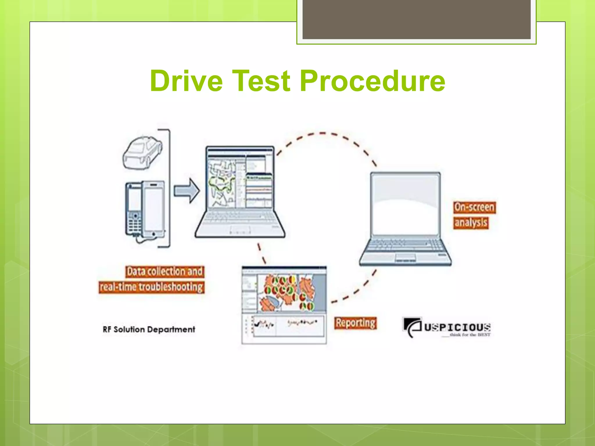
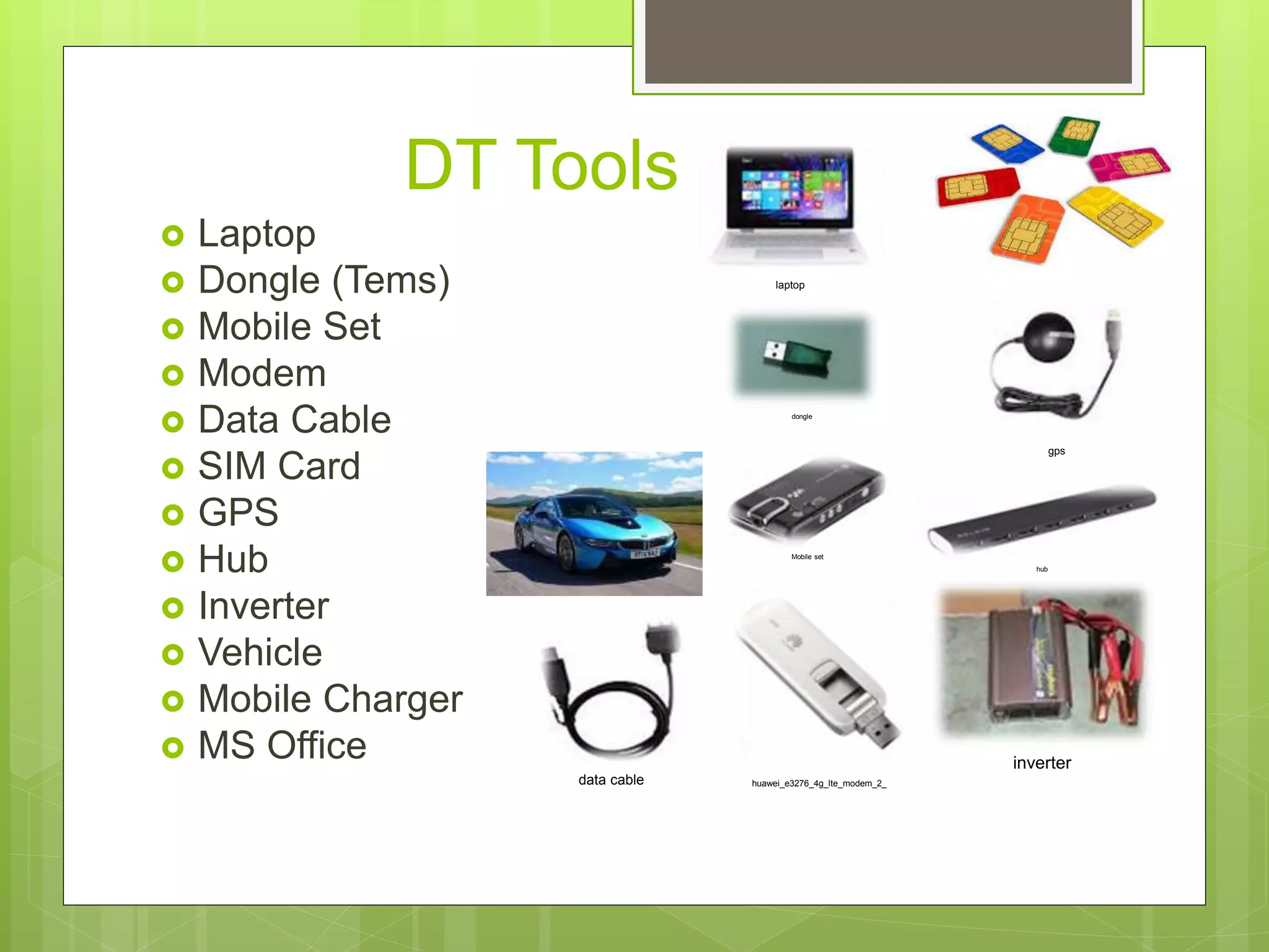


The document discusses drive testing using TEMS Investigation software. It provides an overview of the tools needed for drive testing including a laptop, dongle, mobile set, modem, GPS, and more. It outlines the steps to setup the software and ensure all tools are connected and functioning properly. These include attaching the required devices, loading cell files, and selecting the log collection location. The document also describes some key parameters that can be analyzed during drive testing like signal strength, interference, and throughput.
Introduction to TEMS Investigation as the standard tool for wireless network testing used in over 180 countries.
Detailed steps for conducting drive tests, including tools required, pre-checks, connectivity setup, and route preparation.
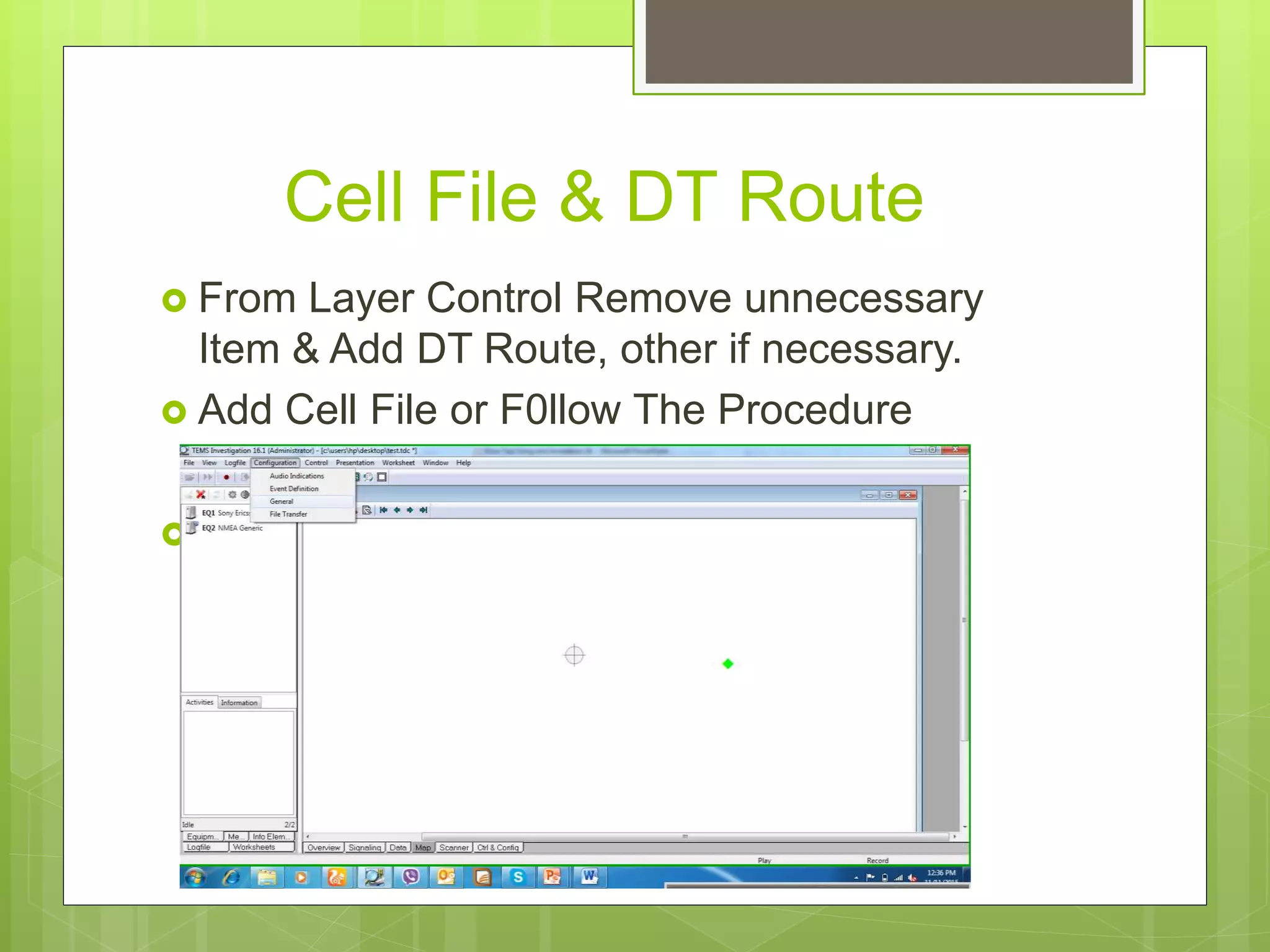
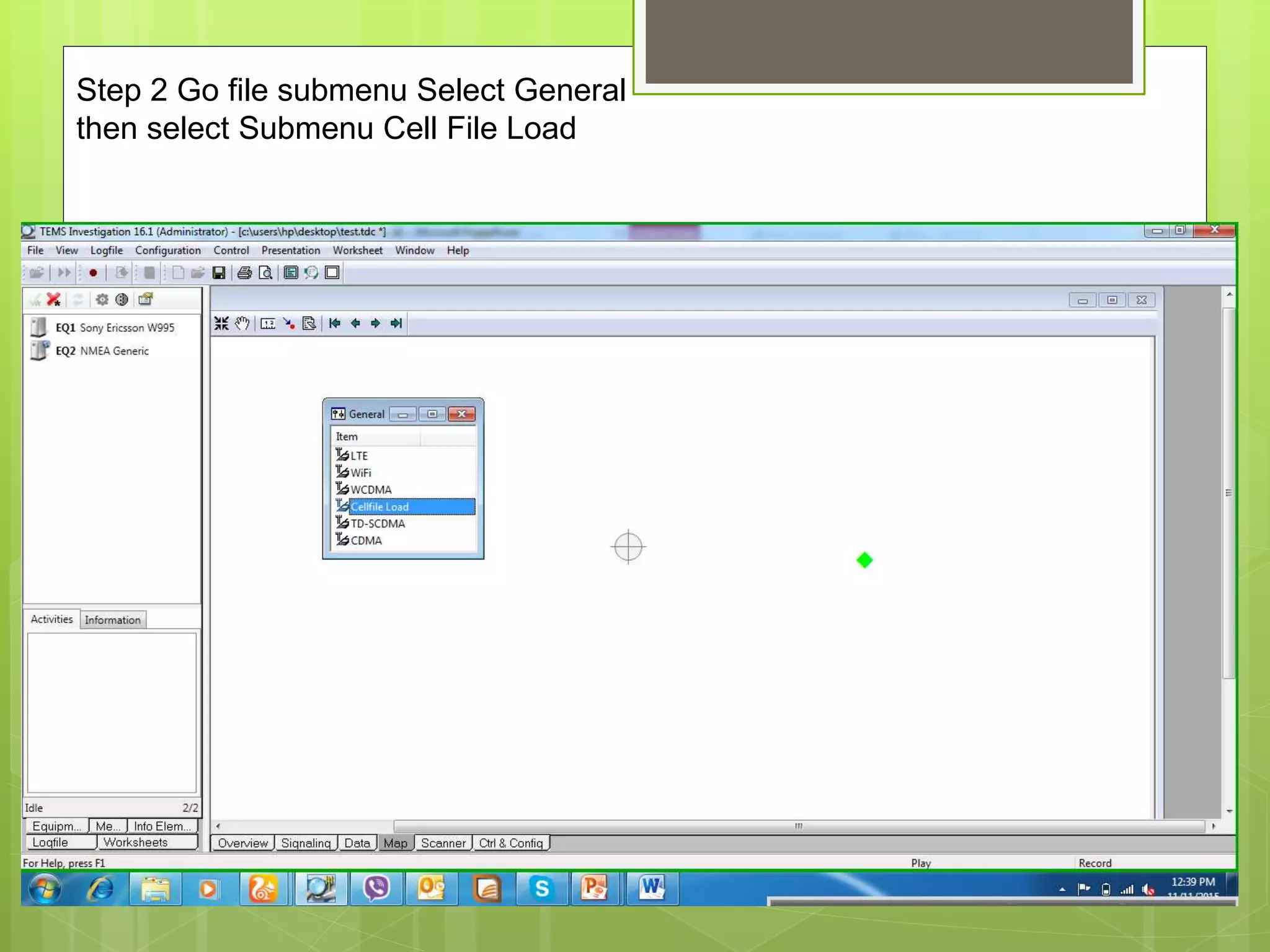
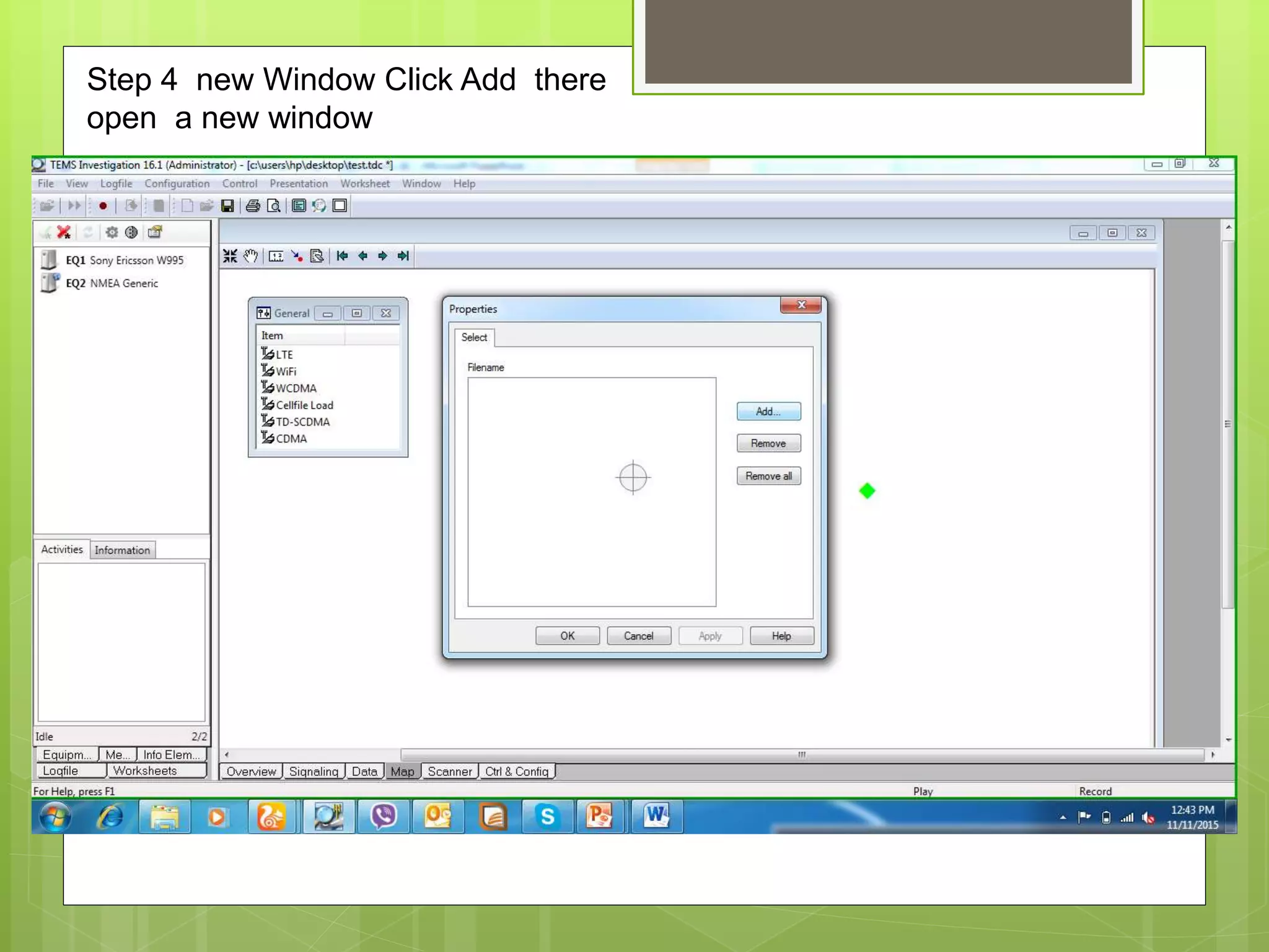
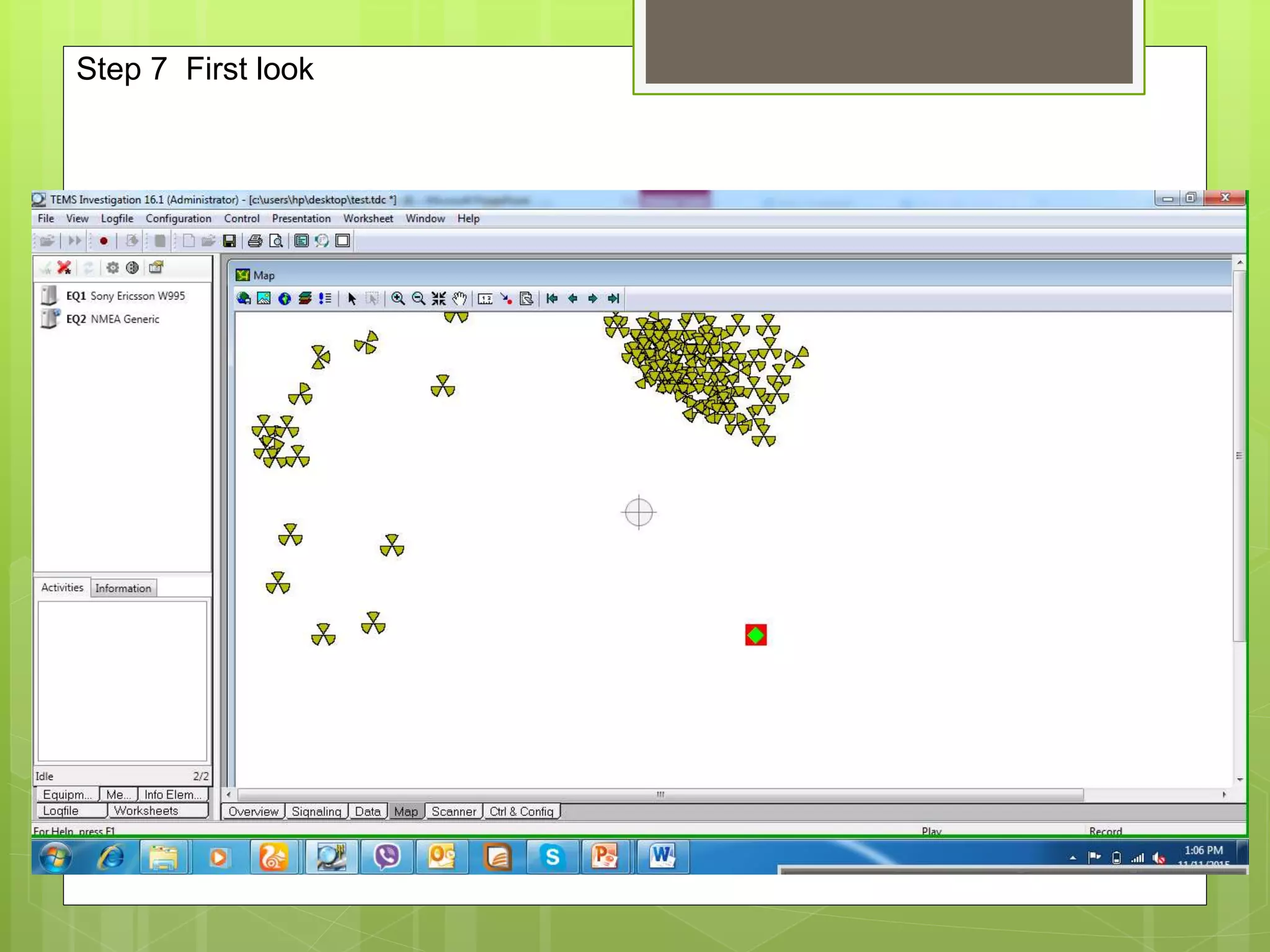
Steps to load cell files into the TEMS Investigation software, ensuring proper configuration for the drive test.
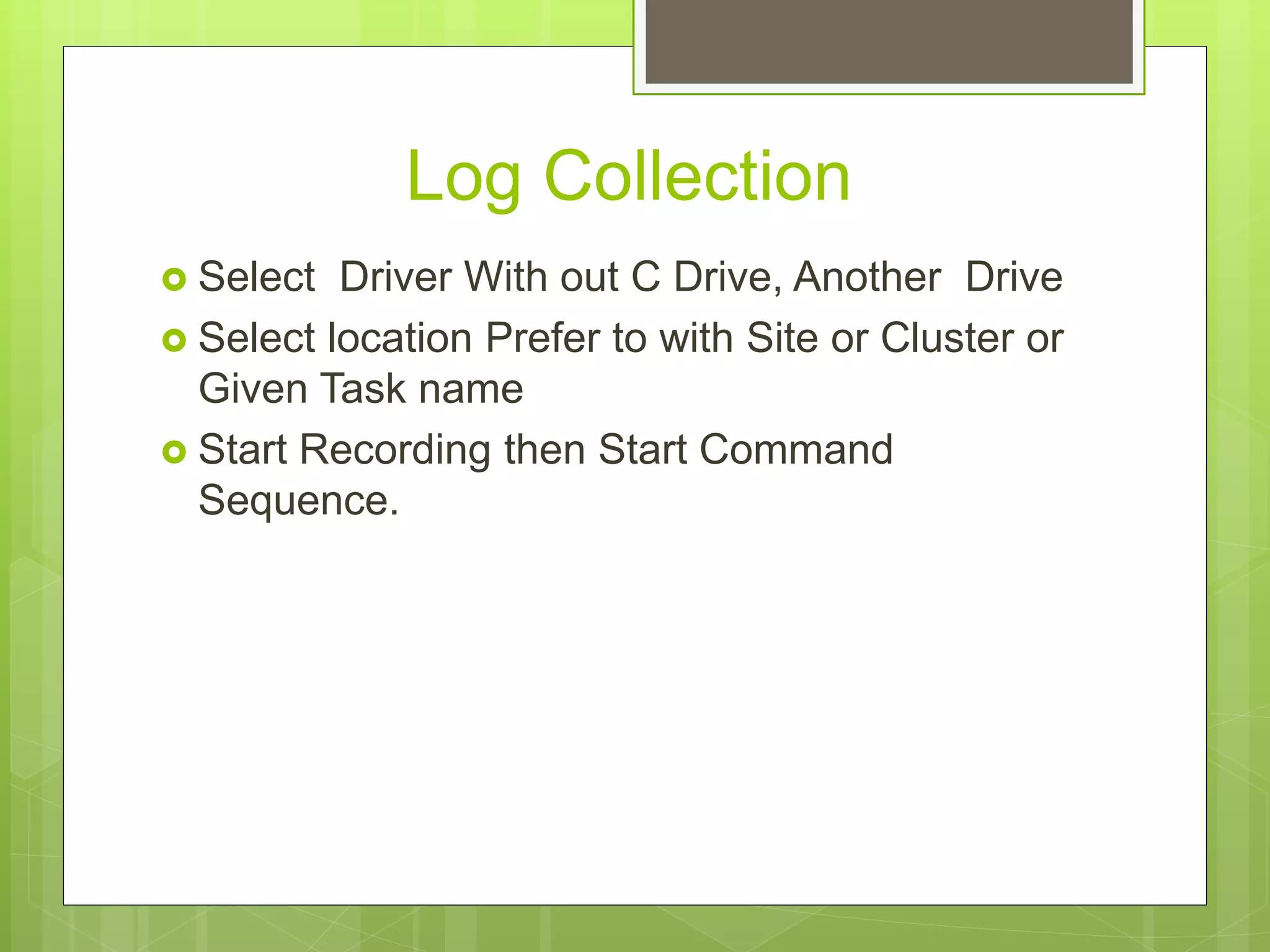
Instructions for selecting drivers and locations for log collection during the drive test.
Describes the command sequence for conducting drive tests and the backup requirements for essential software and drivers.
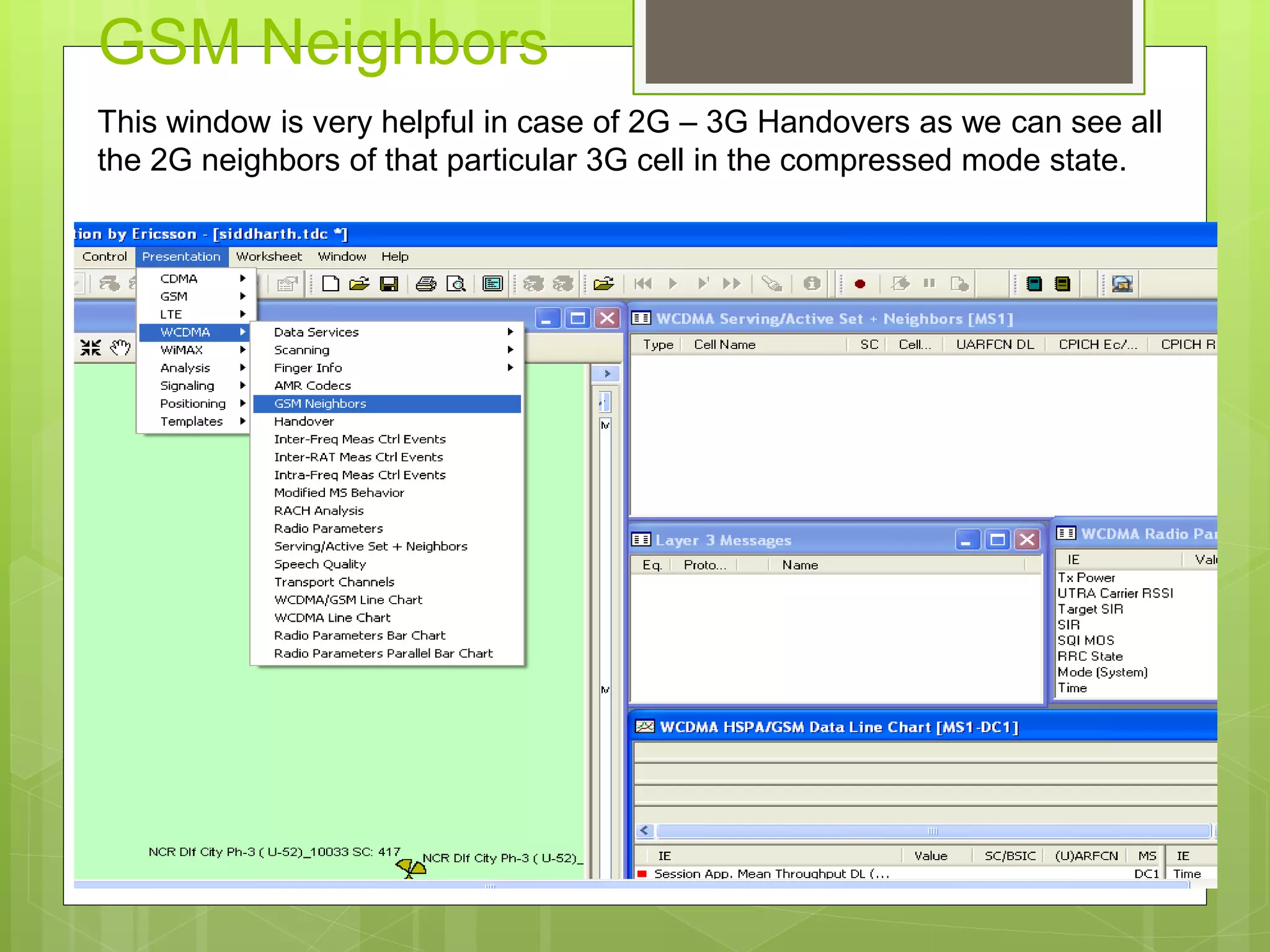
Details on GSM neighbors and serving sets, emphasizing their role in handover processes and network optimization.
Critical radio parameters impacting call quality and signal performance including CPICH Ec/No, Tx Power, and SQI.
Analysis of data speeds in different modes, conveying throughput measurements for 3G and 2G technologies.
Closing remarks of the presentation, summarizing the importance of the information presented.


