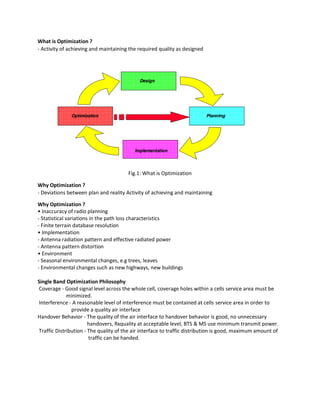
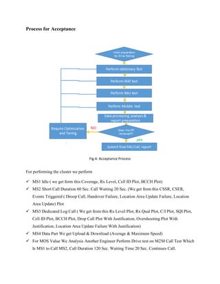
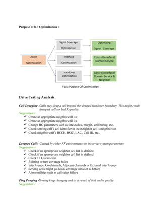
This document discusses radio frequency (RF) optimization, which involves activities to achieve and maintain the required network quality as designed. Reasons for optimization include inaccuracies in radio planning, implementation issues, and environmental changes. The key goals of single band optimization are to provide good coverage and interference levels, as well as good handover behavior and traffic distribution. The optimization process involves site audits, parameter verification, problem identification and prioritization, solution implementation, and retesting. Drive testing is then analyzed to identify issues like cell dragging, dropped calls, ping ponging, and handover boundary problems in order to propose corrective actions.
Achieving Optimal Network Performance Through Continuous Optimization
1. What is Optimization ?
- Activity of achieving and maintaining the required quality as designed
Lucent Technologies Proprietary
Lucent Technologies
Fig.1: What is Optimization
Why Optimization ?
- Deviations between plan and reality Activity of achieving and maintaining
Why Optimization ?
• Inaccuracy of radio planning
- Statistical variations in the path loss characteristics
- Finite terrain database resolution
• Implementation
- Antenna radiation pattern and effective radiated power
- Antenna pattern distortion
• Environment
- Seasonal environmental changes, e.g trees, leaves
- Environmental changes such as new highways, new buildings
Single Band Optimization Philosophy
Coverage - Good signal level across the whole cell, coverage holes within a cells service area must be
minimized.
Interference - A reasonable level of interference must be contained at cells service area in order to
provide a quality air interface
Handover Behavior - The quality of the air interface to handover behavior is good, no unnecessary
handovers, Rxquality at acceptable level, BTS & MS use minimum transmit power.
Traffic Distribution - The quality of the air interface to traffic distribution is good, maximum amount of
traffic can be handed.
2. Optimization Phase
Site Audit
Proper Parameters use
Verify Neighbors list
Reviewing Frequency Plan
Verify existing coverage, site design objectives
Analysis & Identification of Problem areas/cells
From PMS & drive test statistics,
customer complaints
Prioritization of problems
Identify Solution and Implement
Retest the problem areas
Consistency Check of the OMC database
Fine-tuning of parameters
Ongoing process, weekly optimization
Database maintenance and consistency audits
Fig.2: Optimization Phase
3. Cluster Drive test Optimization:
Fig.3: Cluster Optimization
Basic Process:
4. Process for Acceptance
Fig.4: Acceptance Process
For performing the cluster we perform
MS1 Idle ( we get form this Coverage, Rx Level, Cell ID Plot, BCCH Plot)
MS2 Short Call Duration 60 Sec. Call Waiting 20 Sec. (We get from this CSSR, CSER,
Events Triggered ( Droop Call, Handover Failure, Location Area Update Failure, Location
Area Update) Plot
MS3 Dedicated Log Call ( We get from this Rx Level Plot, Rx Qual Plot, C/I Plot, SQI Plot,
Cell ID Plot, BCCH Plot, Drop Call Plot With Justification, Overshooting Plot With
Justification, Location Area Update Failure With Justification)
MS4 Data Part We get Upload & Download (Average & Maximum Speed)
For MOS Value We Analysis Another Engineer Perform Drive test on M2M Call Test Which
Is MS1 to Call MS2, Call Duration 120 Sec. Waiting Time 20 Sec. Continues Call.
5. Purpose of RF Optimization :
Fig.5: Purpose Of Optimization
Drive Testing Analysis:
Cell Dragging -Calls may drag a cell beyond the desired handover boundary. This might result
dropped calls or bad Rxquality.
Suggestions:
Create an appropriate neighbor cell list Proprietary
Create an appropriate neighbor cell list
Change HO parameters such as thresholds, margin, cell baring, etc..
Check serving cell’s cell identifier in the neighbor cell’s neighbor list
Check neighbor cell’s BCCH, BSIC, LAC, Cell ID, etc..
Dropped Calls -Caused by either RF environments or incorrect system parameters
Suggestions:
Check if an appropriate neighbor cell list is defined
Check HO parameters
Existing or new coverage holes
Interference, Co-channels, Adjacent channels or External interference
Serving cells might go down, coverage smaller as before
Abnormalities such as call setup failure
Ping Ponging -Serving keep changing and as a result of bad audio quality
Suggestions:
6. Check if an appropriate neighbor cell list is defined
Check if an appropriate neighbor cell list is defined
Check HO parameters
Interference, Co-channels, Adjacent channels or External interference
Lack of dominant server
Poor coverage
Not optimal antenna configuration
System Busy -System busy on several call attempts and site appears consistently on the traffic
report
Suggestions:
Short Term
Reduce the traffic on the congested cell/site. However, the proposed changes MUST NOT create
any unacceptable problems such as coverage holes, dropped calls, etc Short term solutions are re-
design the antenna configuration, Add additional RTs, Change BTS configuration
Long Term
• Build a new cell site to off-load traffic
Handover Boundary -Handovers do not occur at the desired HO boundary, the result is an
imbalance in traffic distribution across the system
Suggestions:
Check if an appropriate neighbor cell list is defined
Check HO parameters
Inappropriate antenna configurations of the serving and neighbor cells
Interference, Co-channels, Adjacent channels or External interference
No TCH available (neighbor cells congestion)
7. Customer Complain
Fig.6: Customer Complain
Procedure On Customer Complain:
Initial Ticket on Customer Complain
Assign task on Drive Test Engineer
Initial Drive on Based on Customer Complain
Drive Test Analysis Report Prepare
Based On Report Change Proposal Implementation
Yes
NO
8. Verification Drive Test Do.
Drive Test Analysis Report Prepare Based On Verification Drive Test.
If Meet the target KPI submitted the report & Close Ticket. Otherwise finding the issue &
Retry to solve it
Move on Next Customer Complain.
Indoor Walk Test:
Fig.7: Indoor Walk Test
Procedure on Indoor Walk Test:
Initial Drive Test on IBS Site as Walk test in indoor & Drive test as outdoor.
Proposed PRRU Location Based on Walk Test.
Verification Walk Test & Drive Test & Analysis the Dive Test
If Meet the target KPI submitted the report & Close Ticket. Otherwise finding the issue &
Retry to solve it
Move on Next IBS Sites.
Yes
NO