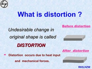
What is distortion?
Undesirable change in
Undesirable change in
original shape is called
original shape is called
DISTORTION
DISTORTION
Before distortion
After distortion
Distortion occurs due to heat input
and mechanical forces.
RKS,HZW
3.
• Uniform heatingof a steel bar through out of its entire volume -
considerable expansion take place in all direction.
• Now, if cooling of the bar is allowed evenly - retain its original
shape and size without distortion.
DURING HEATED CONDITION
X
X + 9X
BEFORE HEATING AND AFTER COOLING
Experiment No 1:
RKS,HZW
4.
So, we cansay that,
“ Uniform heating and cooling of
a component that can expand
and contract does not cause
any appreciable distortion ”
RKS,HZW
5.
• Repeat experimentno:1 but heat the steel bar in
clamp condition and see the changes in shape and size
after cooling.
STEEL BAR AFTER
HEATING & COOLING DOWN
STEEL BAR BEFORE
HEATING
CLAMPING
JAWS
CLAMPING
JAWS
Experiment No 2 :
RKS,HZW
6.
So, we canconclude that,
• Restraint hinders free expansion and
contraction and causes material to
deform resulting in
Distortion
RKS,HZW
HEATING
Heated areaexpands
Expansion restrained by surrounding solid area
Compressive stresses are developed
Further compressive stress leads to plastic deformation
Material bulges at the spot towards heat source side
HEAT SOURCE
Distortion in case of spot heating?
RKS,HZW
9.
COOLING
Spot areatends to contract.
Contraction restrained by surrounding hot area.
Material goes back to original position with plastic
deformation.
Resulting distortion
Distortion in case of spot heating?
RKS,HZW
It iscontraction along the length of weld bead
It is maximum along weld bead and decreases at
points away from the bead.
In C/S of shell it lead to reduction in diameter at
the
weld
Distortion in Butt welds
Longitudinal Distortion
RKS,HZW
12.
LONGITUDINAL SHRINKAGE
• (A)BUTT WELDS IN CS/LAS
LS = 3. I .L / 100,000 t
LS = longitudinal shrinkage (mm)
I = welding current(amp)
L = length of weld (mm)
t = plate thickness (mm)
RKS,HZW
13.
EXAMPLE (LS INBUTT WELDS)
• Calculate LS for 6mm thick CS plate
welded by SMAW using 200 A current.
• Solution : LS = 3. 200. L / 100,000 x 6
= L/1000 mm
RKS,HZW
14.
LONGITUDINAL SHRINKAGE
LS =25 Aw/ Ap
Aw = Weld X-sectional area
Ap = Resisting X-sectional area
Ap
Aw
• (B) FILLET WELD
RKS,HZW
15.
EXAMPLE OF LSIN FILLET
WELD
100
75
6
6
8x8
All dimensions in mm
LS = 1.52 mm
RKS,HZW
16.
It isthe shrinkage perpendicular to the weld.
It leads to the development of high residual stress and
also cracking in case of highly restrained joint.
It is not uniform along the length of the plate
It is lesser at that end of plate where bead is started.
Distortion in Butt welds
Transverse Distortion
RKS,HZW
TRANSVERSE SHRINKAGE IN
SINGLEPASS BUTT JOINTS
S = 0.2 Aw / t + 0.05 d
Where
S = Transverse Shrinkage (mm)
Aw = Cross sectional Area of Weld (mm2
)
t = Thickness of Plates (mm)
d = Root Opening (mm)
RKS,HZW
19.
TRANSVERSE SHRINKAGE
DURING MULTIPASSWELDING
TS = TS0 + b (log w - log w0)
Where
TS = Total Transverse Shrinkage
TS0 = Transverse Shrinkage after first pass
w = Total weight of weld metal
w0 = weight of first pass weld metal
b = a coefficient
RKS,HZW
20.
Effect of VariousProcedures on
Transverse Shrinkage of Butt Welds
Procedures
Root Gap
Joint design
Electrode dia.
Degree of constraint
Peening
Gouging & repairs
Effect on TS
TS increases with increase in RG
Single Vee produces more TS than
double V
TS decreases with increase in electrode
dia.
TS decreases with Degree of constraint
TS decreases by peening
TS increases by these operations.
RKS,HZW
21.
TRANSVERSE SHRINKAGE
IN FILLETJOINTS
1. For T joints with two continuous fillets.
TS = Leg of fillet Weld (l) x 1.02
Bottom Plate thickness (tb)
All dimensions in mm.
tb
l x l
RKS,HZW
22.
2. For intermittentfillet welds , a correcting
factor of proportional length of fillet weld to
total length of joint should be used.
TRANSVERSE SHRINKAGE
IN FILLET JOINTS
RKS,HZW
23.
(3) For filletwelds in a lap joints between
plates of equal thickness (two welds)
TS = Leg of fillet Weld (l) x 1.52
Plate thickness (t)
All dimensions in mm.
TRANSVERSE SHRINKAGE
IN FILLET JOINTS
l
l
t
t
RKS,HZW
It isthe bending transverse to the weld.
Due to non-uniform heating and cooling along
the thickness of plate.
This is the main source of mismatch and
dimensional inaccuracy in large welded
structures
Distortion in Butt welds
Angular Distortion
RKS,HZW
26.
Angular Distortion inButt Joints
t1
t2
t3
g
g = 3 mm
t3 = 2 mm
t
t1 + 1/2 t3
t
= 0.6
1. Use Both Side Welding Technique in place of Single Side Welding
RKS,HZW
27.
AD = 0.0076. W . l1.3
t2
Where
AD= Angular Distortion, mm
W=flange width, mm
l = weld leg length, mm
t = flange thickness, mm
Angular Distortion in Fillet Welds
W W
AD
AD
t
l
t
RKS,HZW
RKS,HZW
28.
Example of AngularDistortion
in Fillet Welds
Find the angular distortion in a double fillet
weld of a T-joint between a flange 1000 mm
wide and a vertical member when the thickness
of both the members is 6 mm and the weld leg
length = 8 mm
Solution.
AD = =
0.0076 x 1000 x (8)1.3
(6)2
3.15 mm.
RKS,HZW
29.
Multiple Restrained FilletWelds
AD
Ø
L
AD
L
1
4
= Ø
x
L
1
2
2
Ø
AD = Angular distortion, mm.
L = span length, mm.
Ø = angular change, radians
x = distance from weld to the
point where distortion is to be
determined, mm.
RKS,HZW
RKS,HZW
30.
Example of ADin Multiple
Restrained Fillet Welds
In multiple restrained fillet welds the span
length is 1 m and the angular change is 90
at
a distance of 400 mm from the span end,
find the distortion.
Solution.
By putting L = 1000 mm, Ø = 90
= 0.1571 rad.
x = L/2 - 400 = 100 mm in the Formula,
AD = 14.164 mm.
RKS,HZW
Reduce effective shrinkageforce
(A-1) Keep the angle of weld joint to the
barest minimum.
keep the angle of weld joint 45 deg.
MINIMUM ANGLE, LESS WELDING , LESS HEAT INPUT
Hence less distortion
50 deg. +/- 5 deg.
RKS,HZW
36.
Reduce effective shrinkageforce
(A-2) Do not keep root gap more than required
(A-3) Do not do over- welding.
REINFORCEMENT REQUIRE MENT
20 MM (+5/-1)
KEEP REINFORCEMENT UP TO 19 MM
RKS,HZW
37.
50 deg. +/-5 deg.
keep the angle of weld joint 45 deg.
keep fillet size 18 mm/6 mm
19 mm +3/-1
7 mm +3/-1
RKS,HZW
38.
(A-4) Minimize noof passes larger size of
electrodes
Reduce effective shrinkage force
MORE NO OF PASSES LESS NO OF PASSES
RKS,HZW
39.
(A-5) Place weldsnear the neutral axis
N. A.
Reduce effective shrinkage force
RKS,HZW
Balance shrinkageforces
with other forces
(C-2) Back step welding
1 2 3 4
Welding progresion
RKS,HZW
46.
Two identical partsshould be tacked back to back
together before welding as shown
PART -II
PART -I
END PLATES
TACKED
(C-3) Back to back clamping for welding
Balance shrinkage forces
with other forces
RKS,HZW
Bulging of tubesheet of heat
exchanger
TUBE SHEET BULGES DURING SHELL
TO TUBE SHEET WELDING
• Welding of shell to tube sheet
LEADS TO
• Improper seating of gasket and
leakage
• Non uniform projection of tube
ends from tube sheet face
CONTROLLED BY
• Back to back
• Weld optimum fillet size
TUBE SHEET
SHELL
RKS,HZW
50.
Distortion of shelllong seams
Typical weld sequence and distortion observed
1184
mm
DIA
58T MIN LAS.
3200
D/4
D
INSIDE
OUTSIDE
600
2
/3T
1
/3T
T
600
0.2mm GAP
3
JOINT DETAIL WELD SEQUENCE
1
2
3
SMAW
SAW
SAW
BACK
GOUGING
RKS,HZW
51.
Distortion of shelllong seams
1 2 3
1 SET-UP STAGE 4 + 2 + 2 +
2 AFTER SEAL RUN 6 + 4 + 5 +
3 AFTE R O/S WELDING 8 + 6 + 8 +
4 AFTER BACK GOUGING 6 + 5 + 5 +
5 AFTER I/S WELDING 4 + 2.5 + 4 +
LOCATION
STAGE
( D/4 TEMPLATE READING
RKS,HZW
52.
• Caused bylongitudinal shrinkage
of weld
• Reduction in diameter around
circumferential seam
• Reduction in shell length
Controlled by
• Provide compression spiders on
both sides of C/S
• Design weld joint to have minimum
weld metal deposit
• Use restricted heat input
( minimum no. of passes )
CIRCSEAM
JIINT
SHELL
SUGARCANE
EFFECT
Distortion of circumferential seams in shell
C/S
RKS,HZW
53.
Gauge for checkinglong seam
distortion in plate stage welding
PICK IN OR PICK OUT = A-B OR C-D
(MAXIMUM DIFFERENCE TO BE CONSIDERED)
GAUGE
FOR CHECKING
A
B
C
D
RKS,HZW
54.
Gauge for checkingdistortion of
‘T’- joint welding
PRE-TILT OF T-STIFFENER = A - C
SAGGING OF T-STIFFENER = A - B
GAUGE FOR CHECKING
A
B
C
RKS,HZW
55.
Distortion in flangeto pipe welding
FLANGE
BEFORE
WELDING
AFTER
WELDING
PIPE
FLANGE WARPS
FLANGE FLANGE
PIPE PIPE
TEMP. SUPPORTS
• Heavy fillet weld on flange to pipe joint leads to warping
of flange
• Causing no machining allowance on flange face thickness
CONTROL : back to back welding
• Temporary set up two flanges back to back as shown
RKS,HZW
56.
Sinking in ofnozzle on shell
Controlling sinking
• Provide rigid internal jacks
/supports with moon plates
/compression spider
• Maintain optimum weld
preparation and fit up to avoid
extra weld deposit
• Keep excess nozzle projection
at set up stage to compensate
for sinking
RKS,HZW
57.
STRIP CUTTING FROMPLATE
The strip tends to bow outwards as shown
Distortion ( bow ) results due to unequal heating of
the metal
During cutting when hot, the bow is more on cooling
& the bow diminishes slightly
Finally the strip never returns to it’s intended shape
PLATE
STRIP
Distortion During Oxy-acetylene
Cutting
RKS,HZW
58.
Controlling distortion duringoxy-
acetylene cutting
METHOD I
Two Torches Technique
• Mark strip of required width leaving 10 mm distance
• Move two torches simultaneously carrying out cutting operation
SCRAP 10 mm
TORCH I
TORCH II
STRIP
PLATE
DIRECTION OF MOVEMENT
FOR TORCHES
RKS,HZW
59.
Controlling distortion during
oxy- acetylene cutting
Method II
• Mark the strips with kerf allowance on the plate
• Drill small hole in kerf allowance at distance 20 mm away from
the edge
• Start cut from drilled hole in kerf to the end such that the strip
is attached to main plate
• Cut the balance strip attached to the plate
HOLE
PLATE
STRIPS
KERF
RKS,HZW
60.
Controlling distortion during
oxy- acetylene cutting
Aim : To get undistorted segment from the plate of size as
shown
Specific Steps
• Mark leaving 30mm Dist. from edge
• Start with pierce cut as shown instead of starting from the
edge
• Follow the path as shown
30 mm
30 mm
12 mm THK
PLATE
50 mm
PIERCE
START
R250 mm
RKS,HZW
61.
Reduction in distortion
•Less weld edge preparation.
• Less welding current as per WPS.
• Higher base metal thickness.
• Lesser welding passes
• Do not over weld
• More distortion in stainless steel then carbon
steel.
• Less offset-Lesser welding-Lower distortion
RKS,HZW
62.
• Provide intermittentwelding
• Place weld near the neutral axis
• Balancing weld around neutral axis
• Back-step welding
• Sequence welding
• Pre bending OR Pre cambering
• Back to back clamping
• Double operator welding technique
Reduction in distortion
RKS,HZW