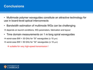
The document discusses dispersion studies on multimode polymer spiral waveguides for board-level optical interconnects, highlighting the advantages of optical interconnects over electrical ones, particularly in capacity and efficiency. It outlines the technological requirements for implementing such waveguides, including cost-effectiveness and compatibility with existing systems, and presents findings on bandwidth performance, indicating high potential for data transmission rates. The study emphasizes that multimode polymer waveguides can achieve bandwidths suitable for very high-speed communication, with experimental evidence supporting their efficiency.


![Evolution of Optical Interconnects
• Optical interconnects will be employed in shorter and shorter links to
meet the bandwidth and power efficiency requirements.
Board Level
[1] A.F. Benner et al, Exploitation of optical interconnects in future server architectures, IBM Journal of Research and
Development, vol 49, Issue 4.5, 2005.
[1]1980’s 1990’s 2000’s > 2012](https://image.slidesharecdn.com/presentationoic2015jianchen-161113232208/85/Dispersion-Studies-on-Multimode-Polymer-Spiral-Waveguides-for-Board-Level-Optical-Interconnects-5-320.jpg)


![VCSEL Performance
Continuous improvement in bandwidth performance of VCSELs:
850 nm VCSELs:
44 Gb/s (2012), 57 Gb/s (2013) and 64 Gb/s (OFC 2014, Chalmers - IBM)
performance in longer wavelengths follows same trend
- un-cooled operation up to 90°C: (50 Gb/s Chalmers-IBM, 2014)
- VCSEL arrays with very good uniformity and similarly high bandwidth
[2] P. Westbergh, et al., IEEE PTL, vol. 27, pp. 296-299, 2015
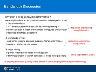
Why do we study the bandwidth of multimode polymer waveguides?
their highly-multimoded nature raises important concerns about their bandwidth
limitations and their potential to support very high on-board data rates.](https://image.slidesharecdn.com/presentationoic2015jianchen-161113232208/85/Dispersion-Studies-on-Multimode-Polymer-Spiral-Waveguides-for-Board-Level-Optical-Interconnects-10-320.jpg)
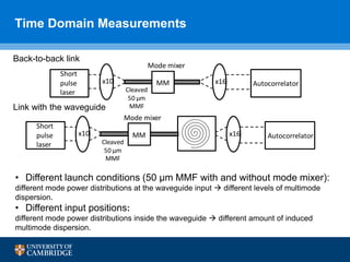
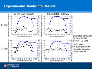
![Frequency Response Measurements
quasi-overfilled 50/125 µm MMF input “overfilled” 100/140 µm MMF input
-3 dB frequency response >35 GHz for all inputs and input positions
suitable for high-speed transmission of ≥ 40 Gb/s data
- results from more overfilled launches into the 1 m long spiral waveguide
50 µm
100 µm
BW > 35 GHz x m
[3] N. Bamiedakis, et al., IEEE JLT, vol. 33, pp. 1-7, 2015
So, what are the bandwidth limits of these particular waveguides ?
time domain measurements](https://image.slidesharecdn.com/presentationoic2015jianchen-161113232208/85/Dispersion-Studies-on-Multimode-Polymer-Spiral-Waveguides-for-Board-Level-Optical-Interconnects-11-320.jpg)


![References
[1] N. Bamiedakis, J. Chen, R. Penty, and I. White, "Bandwidth Studies on Multimode
Polymer Waveguides for ≥ 25 Gb/s Optical Interconnects," in IEEE Photonics Technology
Letters, vol. 26, no. 20, pp. 2004–2007, 2014.
[2] J. Chen, N. Bamiedakis, R. V. Penty, I. H. White, P. Westbergh, and A. Larsson,
“Bandwidth and Offset Launch Investigations on a 1.4 m Multimode Polymer Spiral
Waveguide,” in European Conference on Integrated Optics, p. P027, 2014.
[3] D. Kuchta, et al., "64 Gb/s Transmission over 57m MMF using an NRZ Modulated 850nm
VCSEL," in Optical Fiber Communication Conference (OFC), pp. 1-3, 2014.
[4] N. Bamiedakis, J. Chen, P. Westbergh, J. Gustavsson, A. Larsson, R. Penty, and I.
White, "40 Gb/s Data Transmission Over a 1 m Long Multimode Polymer Spiral Waveguide
for Board-Level Optical Interconnects," in Journal of Lightwave Technology, vol. 33, no. 4,
pp. 882–888, 2014.
[5] B. W. Swatowski, C. M. Amb, M. G. Hyer, R. S. John, and W. K. Weidner, "Graded Index
Silicone Waveguides for High Performance Computing," in IEEE Optical Interconnects
Conference (OIC), pp. 1-3, 2014.](https://image.slidesharecdn.com/presentationoic2015jianchen-161113232208/85/Dispersion-Studies-on-Multimode-Polymer-Spiral-Waveguides-for-Board-Level-Optical-Interconnects-19-320.jpg)