Downloaded 81 times
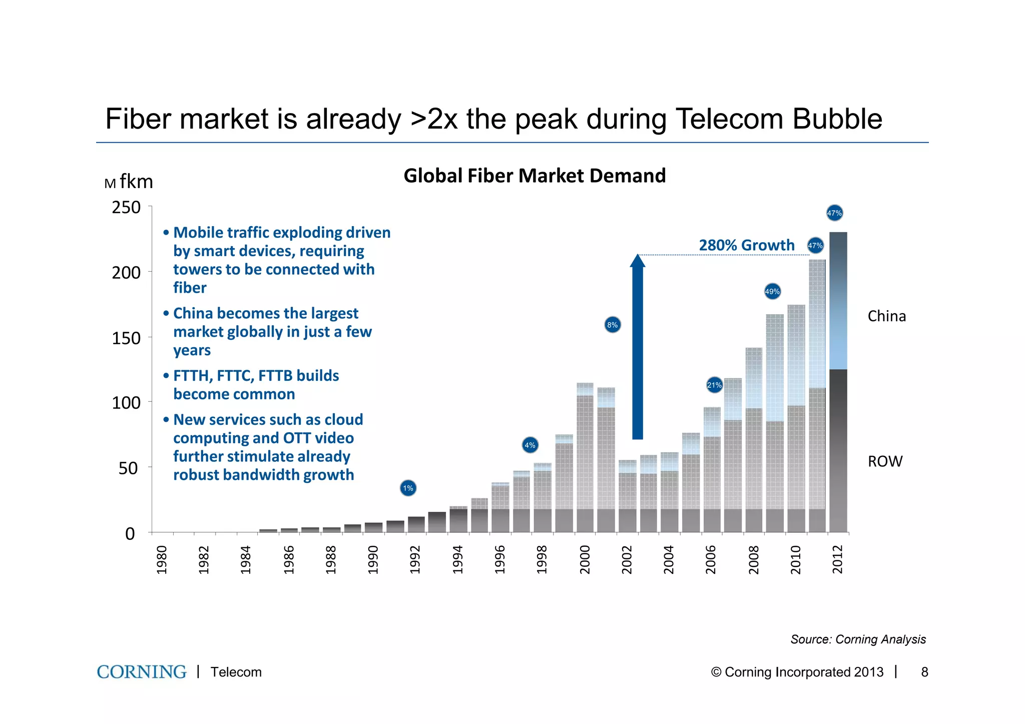


![…And if we are talking about expanding boundaries, why not
combine them ?...
• MCF has 12 single-mode, and two few-mode cores supporting LP01 and LP11 propagation
• SM cores: step-index with mode-field diameter (MFD) of 9 µm at 1550 nm
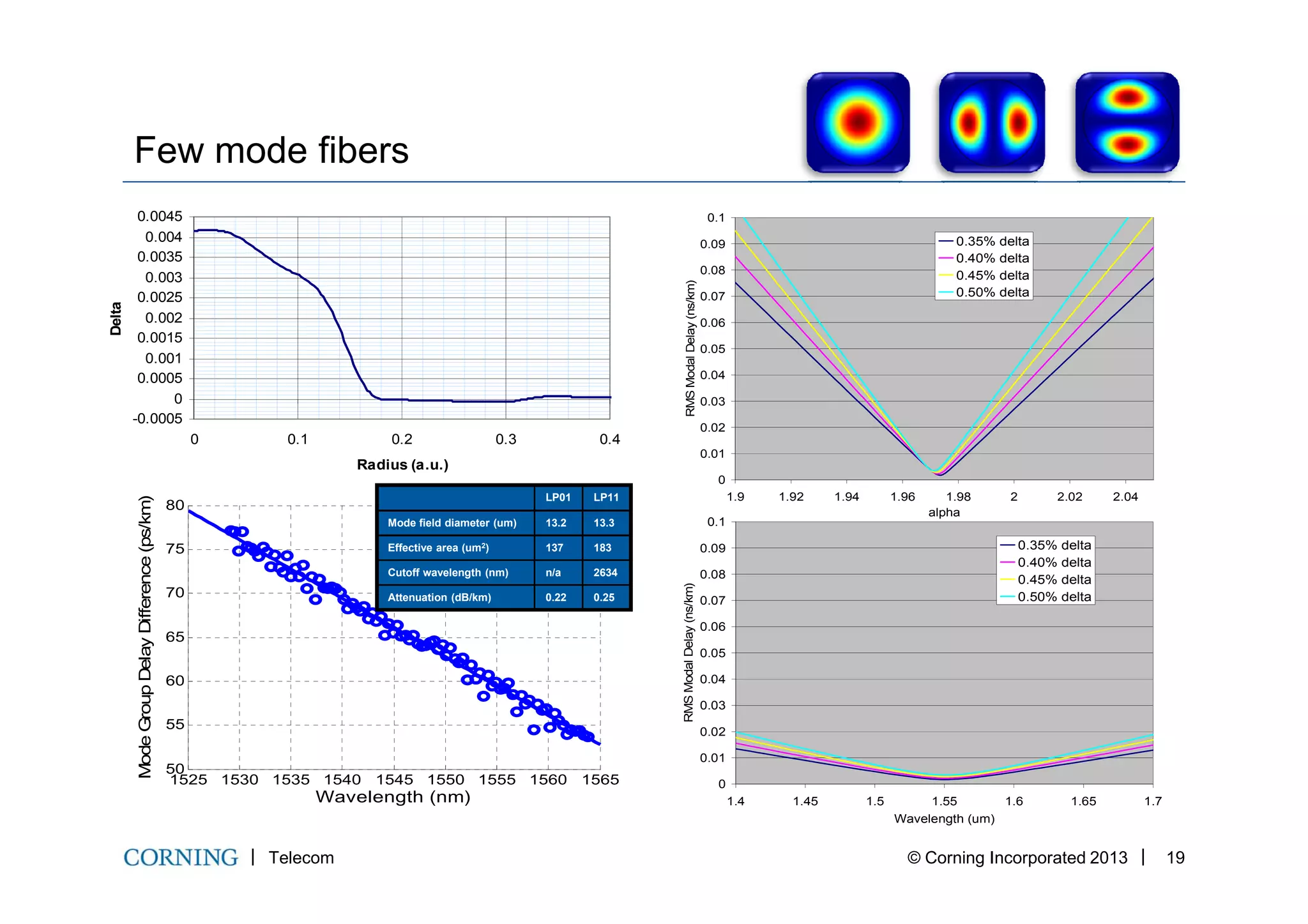
• FM cores: graded index, MFD of LP01 mode is 14 µm at 1550 nm
• Pitch spacing: 45 µm
• 12 cores × [386×91.54 + 384×102.66 ] + 2 cores × 354×213.1 Gb/s = 1.048 Pb/s
• Total bandwidth from 1526.22 nm to 1611.38 nm: 10.38 THz
• “Equivalent” Spectral Efficiency: ~ 110 b/s/Hz.
• (By the way, I personally don’t agree with this “definition”…)
Collaboration Corning – NEC America
Telecom © Corning Incorporated 2013 22
• (By the way, I personally don’t agree with this “definition”…)
SM2 SM6
SM1 SM5 SM1
0
FM
1
SM4 SM9 FM2
SM3 SM8 SM12
SM7 SM11
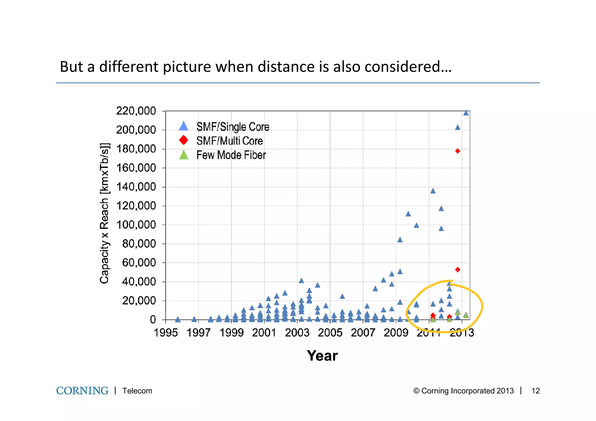
And just to remind ourselves…1 Petabit...per second…
117,281,240,296 pages of plaintext (1,200 characters)
586,406,201 books (200 pages or 240,000 characters)
44,739,243 digital pictures (with 3MB average file size)
33,554,432 MP3 audio files (with 4MB average file size)
206,489 650MB CD's
29,925 4.38GB DVD's
5,243 25GB Blu-ray discs](https://image.slidesharecdn.com/iiwton04claudiomazzalicorning27-28maio13-130912140308-phpapp01/75/Expanding-the-Boundaries-of-Optical-Communications-22-2048.jpg)

![Spansph
ch
NNFPS
P
OSNRout
⋅⋅⋅
=
2/ nAeff∝
FiberFiber
EffectiveEffective
FiberFiber
AttenuationAttenuation
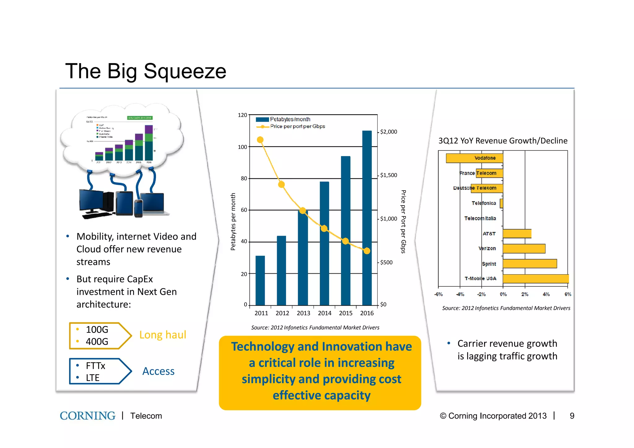
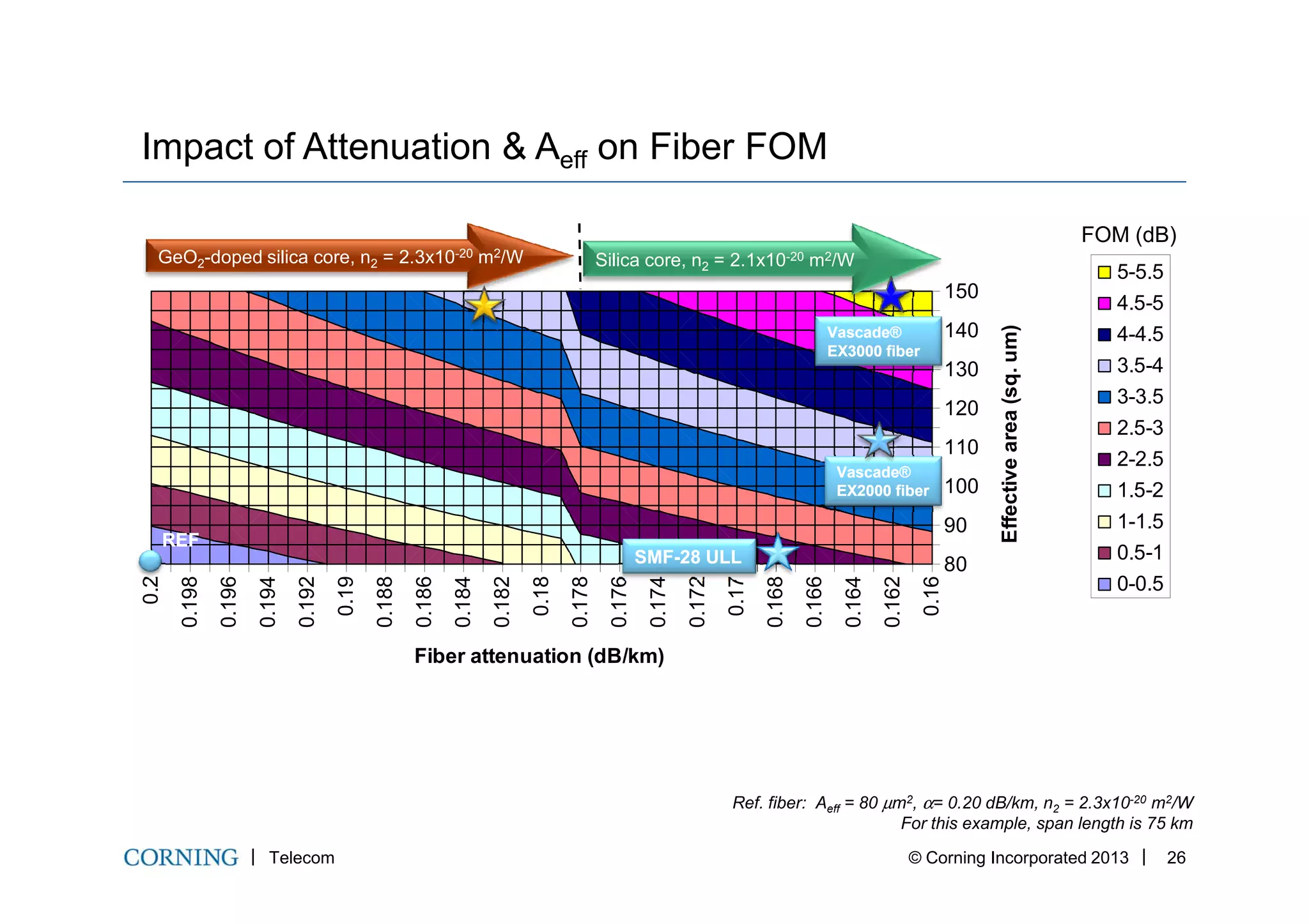
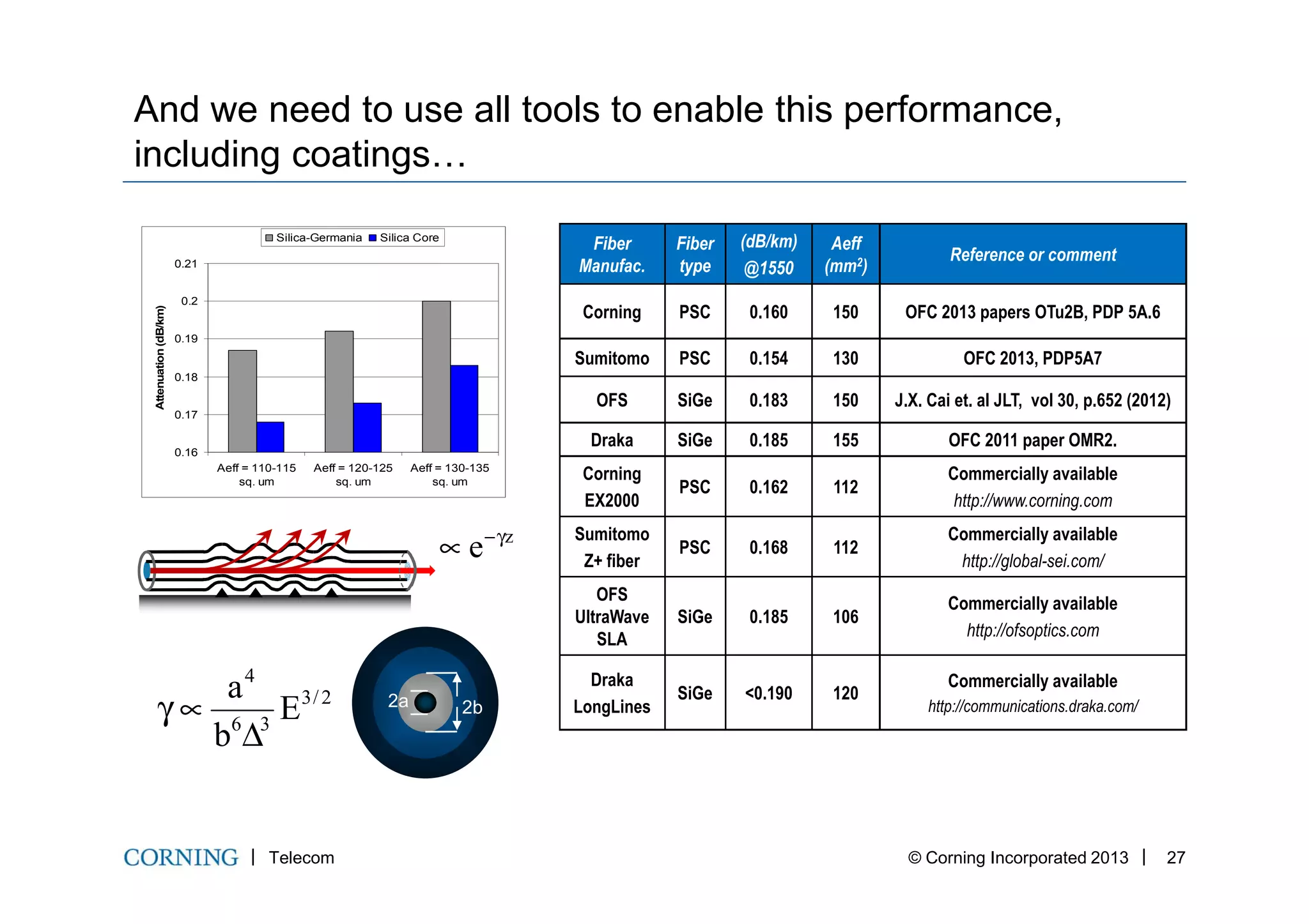
Effect of fiber attributes on OSNR and Fiber FOM
Telecom © Corning Incorporated 2013 25
Spansph NNFPS ⋅⋅⋅
Fiber Independent
)/(nAttenuatio kmdBα∝
EffectiveEffective
AreaArea
AttenuationAttenuation
G. Charlet, ECOC 2010, paper We.8.F.1
[ ]
−⋅−−
⋅
⋅
=
refeff
eff
ref
refeff
refeff
L
L
LkmdBkmdB
nA
nA
,2,
,2
log10)/()/(log10FOM(dB)Fiber αα
N. Bergano, OFC 2009, SubOptic 2010](https://image.slidesharecdn.com/iiwton04claudiomazzalicorning27-28maio13-130912140308-phpapp01/75/Expanding-the-Boundaries-of-Optical-Communications-25-2048.jpg)


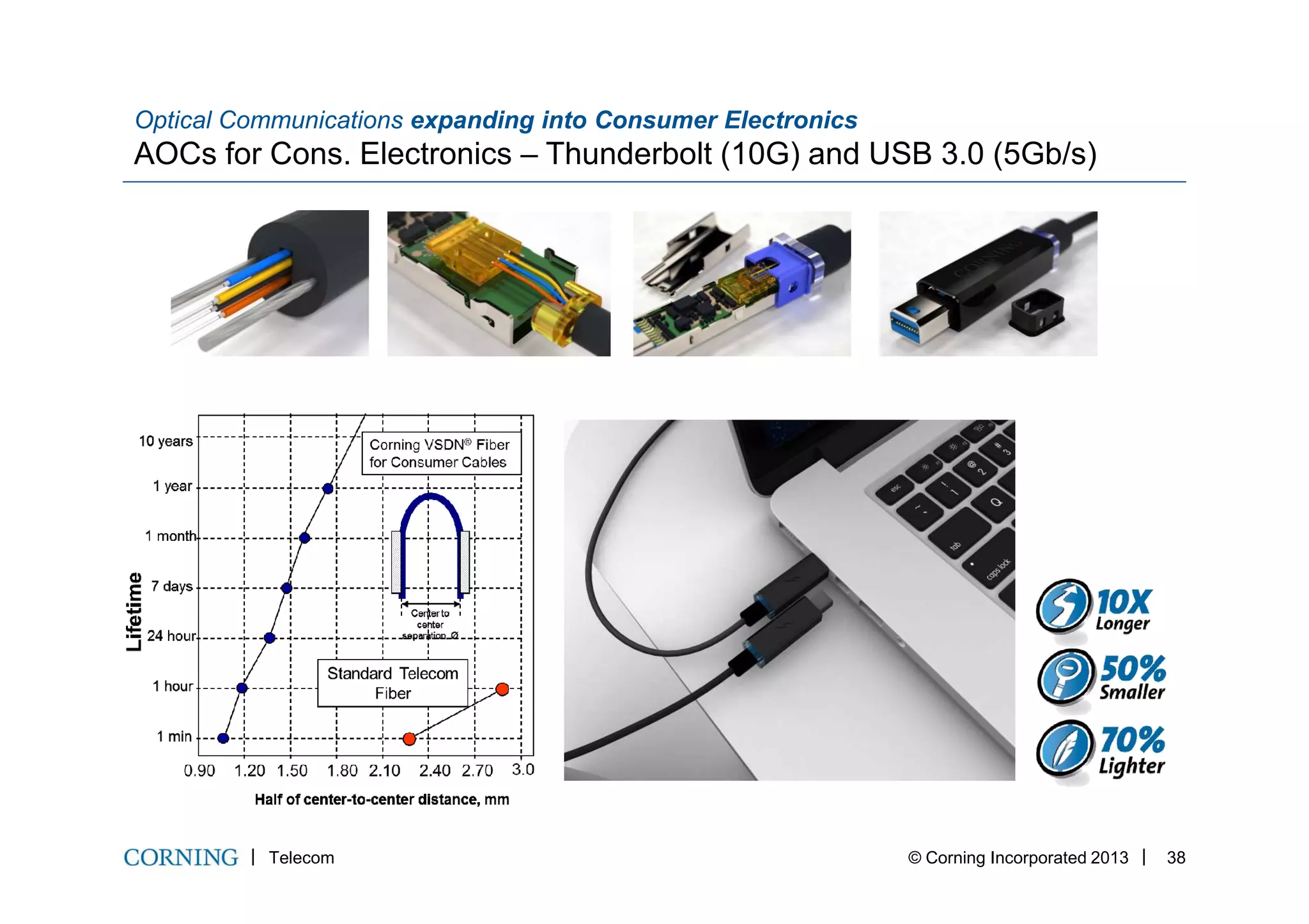


This document discusses emerging optical fiber technologies that are expanding the boundaries of optical communications. It covers multi-core fibers which can increase capacity by transmitting multiple independent data streams through separate cores. It also discusses few-mode fibers which can increase capacity by transmitting multiple modes of light through a single fiber. The document notes challenges with these technologies including coupling light across multiple cores and managing modal dispersion in few-mode fibers. It suggests potential applications like high density data center interconnects for multi-core fibers. Overall, the document examines new fiber designs that aim to address the growing demand for fiber optic network capacity.