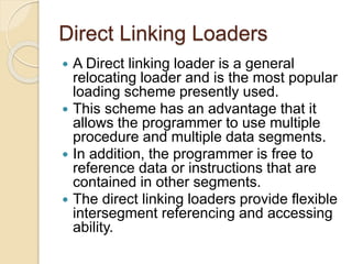
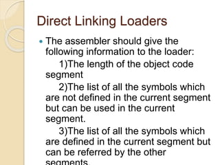
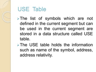
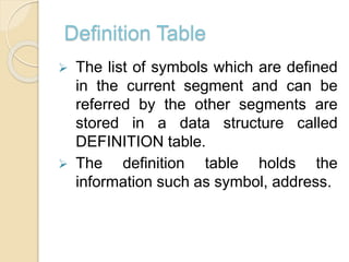
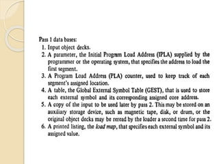
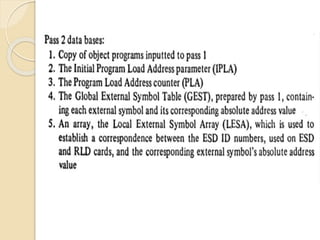
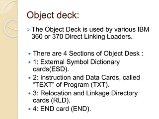
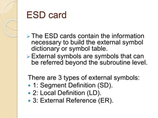
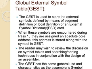
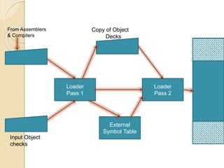
WALCHAND INSTITUTE OF
TECHNOLOGY,SOLAPUR
seminar on
DIRECT LINKING LOADERS
Presented By:
Sneha Bijjargi
Sonali Sulgadle
Anjali Swami
Ankit Palli
Introduction
 To execute an object program, we need
◦ Relocation, which modifies the object
program so that it can be loaded at an
address different from the location
originally specified
◦ Linking, which combines two or more
separate object programs and supplies
the information needed to allow
references between them
◦ Loading and Allocation, which
allocates memory location and brings
the object program into memory for
execution
Type of loaders
 Assemble-and-go loader
 Absolute loader (bootstrap loader)
 Relocating loader (relative loader)
 Direct linking loader
Direct Linking Loaders
 A Direct linking loader is a general
relocating loader and is the most popular
loading scheme presently used.
 This scheme has an advantage that it
allows the programmer to use multiple
procedure and multiple data segments.
 In addition, the programmer is free to
reference data or instructions that are
contained in other segments.
 The direct linking loaders provide flexible
intersegment referencing and accessing
ability.
Direct Linking Loaders
 The assembler should give the
following information to the loader:
1)The length of the object code
segment
2)The list of all the symbols which
are not defined in the current segment
but can be used in the current
segment.
3)The list of all the symbols which
are defined in the current segment but
can be referred by the other
USE Table
The list of symbols which are not
defined in the current segment but can
be used in the current segment are
stored in a data structure called USE
table.
The USE table holds the information
such as name of the symbol, address,
address relativity.
Definition Table
 The list of symbols which are defined
in the current segment and can be
referred by the other segments are
stored in a data structure called
DEFINITION table.
 The definition table holds the
information such as symbol, address.
Object deck:
The Object Deck is used by various IBM
360 or 370 Direct Linking Loaders.
 There are 4 Sections of Object Desk :
 1: External Symbol Dictionary
cards(ESD).
 2: Instruction and Data Cards, called
“TEXT” of Program (TXT).
 3: Relocation and Linkage Directory
cards (RLD).
 4: END card (END).
ESD card
The ESD cards contain the information
necessary to build the external symbol
dictionary or symbol table.
External symbols are symbols that can
be referred beyond the subroutine level.
There are 3 types of external symbols:
 1: Segment Definition (SD).
 2: Local Definition (LD).
 3: External Reference (ER).
Global External Symbol
Table(GEST):
 The GEST is used to store the external
symbols defined by means of segment
definition or local definition or an External
Symbol Dictionary(ESD) card.
 When these symbols are encountered during
Pass 1, they are assigned an absolute core
address; this address is stored along with the
symbol in GEST.
 The reader may wish to review the discussion
on symbol tables and searching/sorting
techniques in conjunction with the design of
an assembler.
 The GEST has the same general use and
characteristics as the assembler’s Symbol
Loader
Pass 1
External
Symbol Table
Loader
Pass 2
From Assemblers
& Compilers
Input Object
checks
Copy of Object
Decks
Direct linking loaders

Direct linking loaders

  • 1.
    WALCHAND INSTITUTE OF TECHNOLOGY,SOLAPUR seminaron DIRECT LINKING LOADERS Presented By: Sneha Bijjargi Sonali Sulgadle Anjali Swami Ankit Palli
  • 2.
    Introduction  To executean object program, we need ◦ Relocation, which modifies the object program so that it can be loaded at an address different from the location originally specified ◦ Linking, which combines two or more separate object programs and supplies the information needed to allow references between them ◦ Loading and Allocation, which allocates memory location and brings the object program into memory for execution
  • 3.
    Type of loaders Assemble-and-go loader  Absolute loader (bootstrap loader)  Relocating loader (relative loader)  Direct linking loader
  • 4.
    Direct Linking Loaders A Direct linking loader is a general relocating loader and is the most popular loading scheme presently used.  This scheme has an advantage that it allows the programmer to use multiple procedure and multiple data segments.  In addition, the programmer is free to reference data or instructions that are contained in other segments.  The direct linking loaders provide flexible intersegment referencing and accessing ability.
  • 5.
    Direct Linking Loaders The assembler should give the following information to the loader: 1)The length of the object code segment 2)The list of all the symbols which are not defined in the current segment but can be used in the current segment. 3)The list of all the symbols which are defined in the current segment but can be referred by the other
  • 6.
    USE Table The listof symbols which are not defined in the current segment but can be used in the current segment are stored in a data structure called USE table. The USE table holds the information such as name of the symbol, address, address relativity.
  • 7.
    Definition Table  Thelist of symbols which are defined in the current segment and can be referred by the other segments are stored in a data structure called DEFINITION table.  The definition table holds the information such as symbol, address.
  • 10.
    Object deck: The ObjectDeck is used by various IBM 360 or 370 Direct Linking Loaders.  There are 4 Sections of Object Desk :  1: External Symbol Dictionary cards(ESD).  2: Instruction and Data Cards, called “TEXT” of Program (TXT).  3: Relocation and Linkage Directory cards (RLD).  4: END card (END).
  • 11.
    ESD card The ESDcards contain the information necessary to build the external symbol dictionary or symbol table. External symbols are symbols that can be referred beyond the subroutine level. There are 3 types of external symbols:  1: Segment Definition (SD).  2: Local Definition (LD).  3: External Reference (ER).
  • 12.
    Global External Symbol Table(GEST): The GEST is used to store the external symbols defined by means of segment definition or local definition or an External Symbol Dictionary(ESD) card.  When these symbols are encountered during Pass 1, they are assigned an absolute core address; this address is stored along with the symbol in GEST.  The reader may wish to review the discussion on symbol tables and searching/sorting techniques in conjunction with the design of an assembler.  The GEST has the same general use and characteristics as the assembler’s Symbol
  • 13.
    Loader Pass 1 External Symbol Table Loader Pass2 From Assemblers & Compilers Input Object checks Copy of Object Decks