Download to read offline
![IJRET: International Journal of Research in Engineering and Technology eISSN: 2319-1163 | pISSN: 2321-7308
_______________________________________________________________________________________
Volume: 04 Issue: 04 | Apr-2015, Available @ http://www.ijret.org 436
5. CONCLUSION
In this paper the Electronic Control Unit (ECU) which is
compatible for both 2-stroke and 4- stroke engine is
designed, fabricated and the output waveforms are tested in
the laboratory using LabVIEW. The slotted optocoupler is
selected as the sensor for sensing the rotational speed of the
crankshaft because it is a general purpose, having well
output signal level and operates at ~1 to 20mA.
Microcontroller (P89V51RD2FN) is interface with LCD
(JHD 162A) to display the mode of operation (2-Stroke or
4-Stroke) of the ECU and RPS (Revolutions per Second) of
the engine to which the ECU is prearranged. The obtained
test results are carefully studied, analyzed and compared
with the theoretical results and the following conclusions
have been drawn.
By varying the resistance of the first Monostable
multivibrator, we can control the actual output
pulse width of injection timing (in ms) i.e. by
increasing the resistance connected to the first
Monostable multivibrator the output pulse width of
PWM signal generated by ECU, is increased and
vice versa.
By varying the resistance connected to the second
Monostable multivibrator, we can control the phase
(Injection starting point) of the output signal.
By triggering the DPDT switch ON and OFF we
can obtain the output PWM signal from the ECU,
which is compatible with 4-stroke engine and 2-
stroke engine.
REFERENCES
[1] Stefan Butzmann, Reinhard Buchhold (2004). “A new
differential magnetoresistive gear wheel sensor with high
suppression of external magnetic fields,” Architecture.
16-19;
[2] L.M. Das, Rohit Gulati and P K Gupta, (2000).
“Performance evaluation of a hydrogen-fuelled spark
ignition engine using electronically controlled solenoid-
actuated injection system,” International Journal of
Hydrogen Energy 25: 569-579;
[3] “Gasoline-Engine Management”, Professional
Engineering publications, Robert Bosch.
[4] Toyota Motor Sales, U.S.A., (1983). “Engine controls -
input sensors”: 1-34;
[5] William J. Fleming, (2001) “Overview of Automotive
Sensors,” IEEE, Sensors (Peterborough, NH) Vol. 1, no.
4: 296-308;
[6] Toyota Motor Sales, U.S.A. “Electronic Fuel Injection
Overview” System: 1-9;
[7] R.A. Reed’, P.W. Marshall, A.H. Johnston, J.L. Barth’,
C.J. Marshall, K.A.LaBel, M. D’Ordine, H.S. Kim6,
M.A. Carts; (1998). “Emerging Optocoupler Issues with
Energetic Particle-Induced Transients and Permanent
Radiation Degradation” IEEE Transactions On Nuclear
Science, Vol. 45, no. 6: 2833-2841;
[8] Mary D' Ordine, (1997). “Proton displacement damage,”
Measurement: 122-124;
[9] N. Saravanan and G. Nagarajan, (2010) “Performance
and emission studies on port injection of hydrogen with
varied flow rates with Diesel as an ignition source,”
Applied Energy 87, no. 7: 2218-2229,
[10] Cathleen Rooman, Daniël Coppée, and Maarten
Kuijk, (2000). “Asynchronous 250-Mb/s Optical
Receivers with Integrated Detector in Standard CMOS
Technology for Optocoupler Applications,” Esprit 35,
no. 7: 953-958;
[11] Oliver Schatz, (2004). “Recent Trends in
Automotive Sensors” Robert Bosch Gmbh, and
Tuebinger Strasse, 236-239;
[12] G.Brasseur, (1997) “Robust Automotive Sensors,”
Technology Conference, Ottawa, Canad, (Peterborough,
NH): 1278-1283;
[13] Wang Sujing, Wang Lide, Shen Ping, Liu Biao,
Nie Xiaobo (2008). “Research on Electronically
Controlled Fuel Injection System,” Design (1849): 2-6;
[14] Todd L. Rachel, (1974). “Automotive Electronic
Fuel Injection Essential Design Considerations -” Vol.
VT-23, No. 2;
[15] E Vargil Vijay, Vargil Kumar E, Ch V Rama Rao,
G N Swamy (2010) “Electronic Control Unit for an
Adaptive Cruise Control System & Engine Management
System in a Vehicle using Electronic Fuel Injection,”
IEEE, Control: 143-146;
[16] David A Williams, (1995) “Optocoupler Selection
For High Frequency Power Supply,” IEEE, Network: 90-
95.
[17] Wei-bin Wu, Tian-sheng HONG, Cai-ru LUO, Hai-
lin WANG, Xue-jun YUE., (2010). “Hardware-in-loop
of Alternative Fuel Engine ECU,” Second International
Conference on Computer Modeling and Simulation: 10-
13,
[18] Daniel Victor Camin abd Gianluigi Pessina, (2000)
“Differential Optocoupler Amplifier with Low Noise,
Low Power and Balanced Output”, IEEE, Transactions
On Nuclear Science, Vol. 47, no. 6: 2039-2044. William
[19] Dunn, (1990). “Automotive Sensor Application”.
[20] Morgan MADEC, Jean-Baptiste KAMMERER,
Luc HEBRARD, (2010). “Animproved compact model
of cross-shaped horizontal CMOS-integrated Halleffect
sensor” IEEE.
[21] Christopher O.Nwagboso (1996). “Automotive
Sensory systems” Chapman & Hall.
[22] Muhammad Ali Mazidi and Janice Gillispie Mazidi
(2006). “The 8051 Microcontroller and Embedded
Systems”, Pearson Education.
[23] W.Bolton (2004). “Mechatronics”, Pearson
Education.
[24] Andrzej M. Pawlak (2006). “Sensors and Actuators
in Mechatronics”, Taylor & Francis.
BIOGRAPHY
Arun Manohar received the B.Tech
degree in mechanical engineering from
Acharya Nagarjuna University, Guntur in
2008 and M.Tech degree in mechatronics
engineering from NIT Karnataka,
Surathkal in 2011.](https://image.slidesharecdn.com/developmentofanelectroniccontrolunitforfuelinjectionofanicengine-160903054833/75/Development-of-an-electronic-control-unit-for-fuel-injection-of-an-ic-engine-7-2048.jpg)

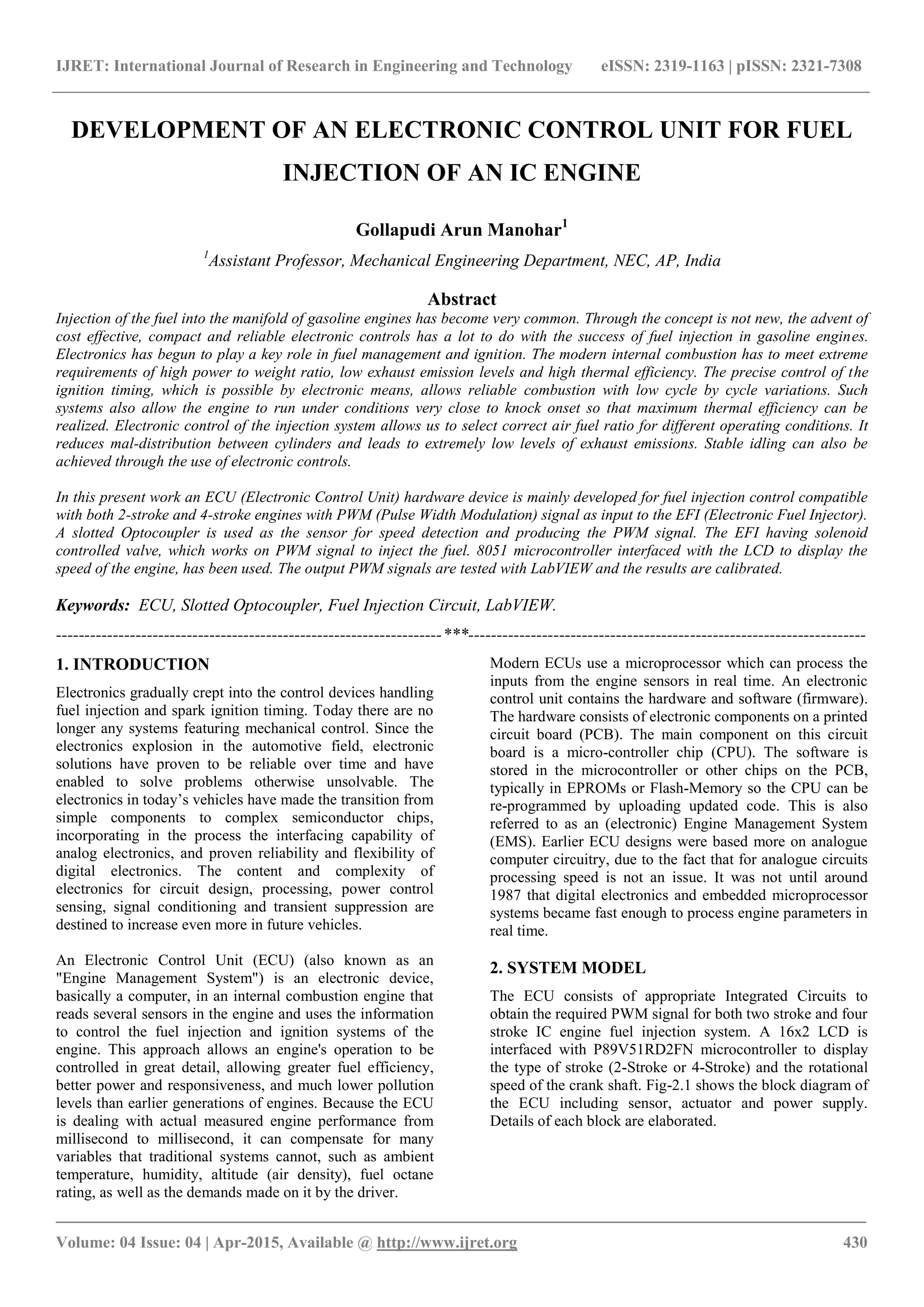
This document discusses the development of an electronic control unit (ECU) for fuel injection control compatible with both 2-stroke and 4-stroke internal combustion engines. It highlights the role of electronics in enhancing fuel management and ignition timing, allowing for improved fuel efficiency, lower emissions, and reliable operation under various conditions. The ECU design incorporates a microcontroller, sensors, and other electronic components to accurately manage fuel injection based on engine performance metrics.